When you click on links to various merchants on this site and make a purchase, this can result in this site earning a commission. Affiliate programs and affiliations include, but are not limited to, the eBay Partner Network.
Wow, I'm subscribing purely because your documentation of everything is exceptional. I don't foresee ever actually getting an FD in my lifetime but I'll be paying attention to how your adventure goes
As for dailying an RX8, I think it would hold up, but it would be more of a case of whatever daily you choose surviving the bay area. I have a friend there that I had to talk out of having a stick car there as his only car. He wound up choosing a brand new Mazda 3 but it's already getting dinged up, assaulted by the weather, and thrashed by the potholes. He ended up taking my recommendation to step down from the stock 18" wheels to 16" Enkeis after his 2nd or 3rd flat tire that resulted in a bent rim. Probably preaching to the choir here though
I feel your friend. I'm lucky to live in a pretty safe residential neighborhood and work at the waterfront. It's been calm enough to where I've taken the RX7 to work semi regularly. I have noticed while the car is down that our municipal transportation agency has been tearing up our roads to try and do.... I don't know.
Thanks for subscribing! I hope an FD lands in your lap - I've always loved driving mine and I'm quite enjoying tinkering with it now, even as a bit of an amateur.
Originally Posted by Molotovman
Twins are king for the spirit of the car, keep them. If you want more power do the BNR's or the Bathurst SP twins.
+1, but after looking for support parts for the twins I am tempted by the simplicity and aftermarket support for singles. And man, the empty space near the downpipe! That must be so nice to have.
Another old car casualty, I've discovered my intercooler has a good few leaks in its core. I've had a local welder put some plugs on the obvious holes, but it seems there is further leaks deeper in the core. Unfortunately, I think the part is junk.
I'll likely hang onto it to get the car started and broken in again, since it technically has been leaking for a while now, but I'm going to have to look for a replacement SMIC for the long run.
Bell makes a bar and plate intercooler core very close to what Greddy used in my Trust intercooler. I'm considering maybe nabbing one to see if I can save the end tanks and graft them onto a new core. Otherwise, I'll have to shell out for a knightsport U-Type.
Auxillary Parts A few remaining pieces between now and the engine coming out.
Fuel Lines, PCV Hose to something? Above the engine bay now, on the drivers’ side, looking down where the TB elbow used to be - 3 Fuel Lines, one supply, one return, one to the charcoal canister. I disconnect them at the engine pipes, and label them A, B, and C. A is the hose going to the top most pipe, B the pipe towards the front of the car, C towards the rear. These are kind of stubborn and there’s not a lot of room to grip them. After a week of sitting, not too much fuel came out. I might do my fuel filter while the system is depressurized.
I’m not sure what this is - there is a Y at the check valve for my PCV lines, one to the UIM to burn and another to some fitting zip-tied to my master cylinder. I pop it off at the check valve and label them both “EVAP”.
Trans Harness The ECU harness I pulled earlier Y’s off and goes to 4x connectors on the transmission, for the output shaft speed sensor, reverse switch, etc. Underneath the car, towards the back end of the body of the gearbox on the drivers' side, you'll see them near the drain and fill plugs. It’s pretty hard to mess these up because each connector is unique and plugs in only one way (thank you, Mazda), but I label them regardless. There is also a clip sitting on the top of the gearbox that retains the harness. From where the connectors were, I shimmy up towards the front of the car near the slave cylinder. It is resting at the top of the gearbox. I used a flatblade screwdriver to pry the loop open and the harness is free. Back on top of the car, on the passenger side, the Trans harness can come up into the engine bay next to the ECU harness.
I label the whole length of harness "Trans". At this point, all electrical connections from the car to the engine should be separated.
Starter Bolt I actually did not catch this until after we fought it for an hour pulling the engine. Part of removing the transmission-block bolts involves removing the starter, as one of the bellhousing bolts is captive under it. One of the bolts is a really long bolt that ties the block to the bellhousing, and has a nut on the other end. Don’t be like me, who threaded that long bolt and nut back through to try not to lose it. Bag it and tag it, or it will hang onto the block while you’re hoisting it out.
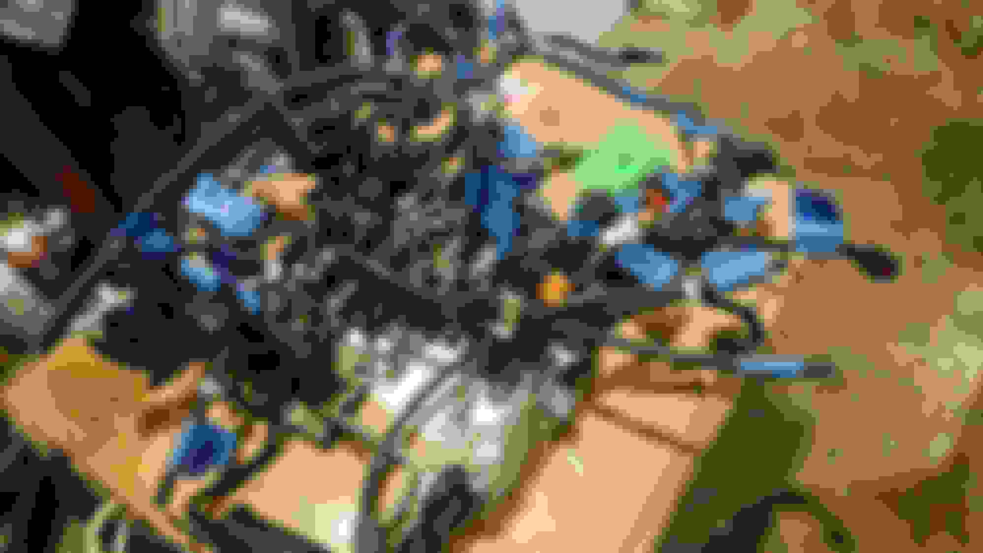
Hoisting the Engine Not as bad as I had imagined. A coworker had lent me his 2-ton Harbor Freight engine hoist. Thank you, Bill! It has enough reach to get to the center of the block and then some, without removing the bumper. With 2 friends over, we roll the car halfway out of our puny garage. I jack the front of the car up and put it on jack stands, I intend to slide my jack under the car and support the body of the gearbox. On either side of the hood, part of the reinforcement “dips” and then comes back up. This is the perfect place to perch 2 pieces of wood from behind the headlight buckets to the dipped surface on the hood, bringing it almost vertical.
I use a small length of chain with a hook on either side, and hook the bracket on the UIM (passenger side) and the bracket behind the alternator (driver side).
We begin by hoisting the engine up a bit, until I can visually confirm the engine mount studs are out of the subframe.
Holding the engine there in the air, I roll my jack under the car and jack up the gearbox, just enough to take weight off the input shaft. Back over the car, we start slightly pulling the engine away from the trans. Ignoring the 1 hour of fighting the starter bolt I left in the car, the engine slides right off the trans.
With the engine off both engine mounts and also the transmission, the engine is out of the car.
This is the first engine any of us have ever pulled out of a car so we're pretty stoked about it. We get the engine mounted onto the engine stand with the pineapple racing adapter and then eat ourselves into a coma at a thanksgiving party.
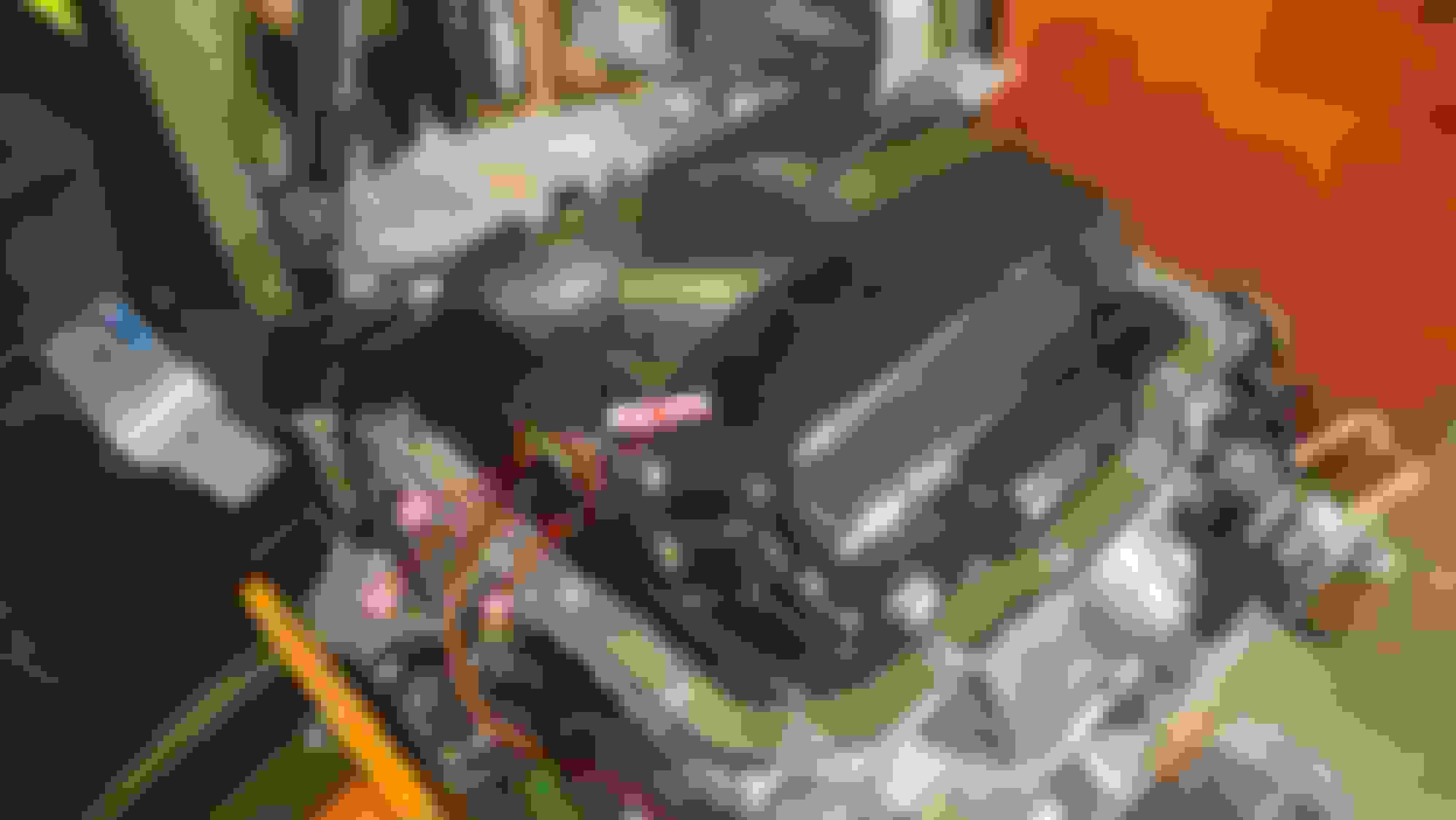
As of today, I have my notes written down having taken off the turbos, exhaust manifold, UIM, and clutch cover+disk. I am procrastinating on taking apart the rats nest, harness, and LIM. Anyone have tips about removing these without making a mess?
UIM and LIM are pretty simple, there are only a few things connected to them, which can be easily label. Once you remove the UIM and the coils, the rats nest can be remove as one assembly with just a few hoses disconnected. This is a good time to refresh all the vacuum hoses and test the solenoids with the rats nest sitting on a work bench, just make sure you follow the vacuum diagram to re-assemble the hoses. The OEM harness is shaped so connectors are usually sitting right next to what they are supposed to connect to, there's a harness diagram on here that list out each connector and what they connect to, so just have that handy and you should be fine.
Shopping List
If anyone is curious, here are the parts I got from Ray earlier this year in anticipation of swapping over the motor:
Throttle Body Coolant Hoses N3A1-13-681A(TB to WP Hose) N3A1-13-691B(Block to TB Hose)
8 of 99286-1400G(Clamps for TB Water Hoses, Turbo Water Hoses)*
*Replacing loose, worn worm drive clamps with OE spring clamps. No matter how much I tighten some of these older ones, the hardened hose refuses to tighten. If you don’t need new clamps you can probably not get these
Radiator Hoses and Clamps N3A1-15-185A(Radiator Hose) N3A1-15-186A(Radiator Hose)
4 of 9WNCB-3900(Rad hose clamps)* N3A1-15-184A(AST to Rad Hose)
Turbo Hoses and Gaskets N3A1-13-536(Turbo Water Hose) N3A1-13-546(Turbo Water Hose)
10 of 99562-1400(Turbo Pipe Crush Washer)**
4 of 99562-1000(Turbo Pipe Crush Washer)** N3A1-13-54X(WP to Turbo Hose)
4 of N3A1-14-293(Turbo Oil Gasket) N3A2-14-293(Also Turbo Oil Gasket)
**This is the amount of crush washers needed to swap the coolant and oil pipes over to new turbos. If you’re sticking with the same turbos, you can reduce the number of these, the pipes will likely stay on the turbo.
Heater Core Hoses FD01-61-211A(Heater Pipe to Heater Core Hose) FD01-61-212A(Heater Core to Heater Pipe Hose) FD01-61-213B(Heater Pipe to Block Hose) FD01-61-214B (Block to Heater Pipe Hose) B455-61-240A(Heater Hose Plastic Adapter Thing)
OMP Hoses and Lines N390-14-602(OMP Tube to OMP Weird Double Washer) N3A1-14-660(OMP Tube) N3A1-14-670(OMP Tube)
2 of 9956-20-800(OMP Tube to Banjo Bolt Washer)
4 of 9956-21-000(OMP Injector Crush Washer)
Water Pump N386-15-162 (WP Housing to Block Gasket) N3A1-15-116(WP Gasket) 8AF6-15-171(TStat Set) N3C1-15-173(TStat Cover Gasket)
Engine Oil Orings N326-10-T11 (Oil Level Sensor O ring)
2 of 9954-10-1601(Oil Filter Pedestal O ring) N3A1-10-424A (Oil Filler Neck O ring)
All this came out to around $400. Thanks, Ray! The most expensive items were the two OMP lines, at $45 each at the time of writing.
Here are some parts I'm ordering now that I have the engine out to assess damage.
Damaged Parts N3A1-13-765(Secondary Charge Hose to Charge Relief Valve)
2 of NF01-13-735 (Clamps for Scndry Charge Hose)
This hose was super hard and brittle, and just swivelled on the secondary air pipe no matter how tight the clamp was. Between this and the intercooler, I wonder how much boost I was leaking?
2 of Dorman 800-801(Replacement clips for oil cooler lines)
A buttload of 99851-825A(Exhaust Studs)
A buttload of JE10-40-355 (Exhaust Manifold to Block Nuts)
I rounded a few of the normal nuts taking the turbo off the exhaust manifold and taking the DP off. (And some of them I found rounded before I got there - Who would put a rounded nut back onto a car??) The parts catalog seems to want to replace the default nuts for the DP and turbo (JE10-48-355, 9YB10-1001) with the ones holding the exhaust manifold to the block. They’re all M10x1.5, I’m more than happy to just change all the exhaust nuts with the extended ones used on the manifold.
There is the one odd 12mm nut holding the secondary turbo to the exhaust manifold, I don’t think that one can be exchanged for a different nut.
Over on the UIM, I remove the bolt on the perch holding the Pressure chamber to it. I believe it is 10mm. I thread this bolt back into the UIM. I leave the other bolt on the Pressure Chamber/Bracket in.
One of the vacuum lines to the pressure chamber going to the Y-Pipe is already disconnected, so I leave this one on the pressure chamber. This must be the P.Chamber pressure source. Neat! The other vacuum line goes into the rats nest, so it needs to come off. I remove it from the pressure chamber and leave it on the rats nest, and label it �Pressure Chamber�.
The crossover bracket is held in with 2x 10mm bolts. I take the bracket, with the P.Chamber attached, off the engine.
Alternator
With the pressure chamber out, the removal path for the alternator is clear. I remove this alternator bracket bolt, 12mm. The bracket can now swing freely.
I remove this pivot bolt on the body of the alternator, 14mm. When this bolt is threaded into the back of the alternator pivot, it squeezes a metal sheathe that presses against the block. I wiggle the alternator about this pivot until I get a clear shot at the pivot point with the rubber mallet. A few firm whacks frees the alternator from the block. I bag and tag both bolts, �Alternator�.
Motor Mounts
I swing the engine upside down on the engine stand. Each motor mount is held in with 3x 14mm bolts. Pretty simple.
Turbo
Every bolt I take out on the turbo I pre-emptively spray with PB Blaster. I don�t know if I need to, I�m happy to never have to find out.
Removing the turbo from the exhaust manifold involves
Removing the lower heat shield, 2x10mm bolts
Removing an actuator vacuum line from the WG
Removing an actuator vacuum line from the TPC (Turbo Pre-Control)
Removing 2x Coolant Hoses
Undoing 1x Oil Supply pipe fitting
Removing 2x Oil Drain Pipes, 2x10mm bolts each
Finally, removing 6x Nuts and 2x Bolts from the turbo to the exhaust manifold (5 x 14mm nuts & 1 x 12mm nut, 2 x 14mm bolts)
Getting surprised at how heavy the twins are when pulling them off
The lower heat shield is held on with just these two 10mm bolts. I take the shield off the turbos and thread the bolts back on.
There are two silicone hoses that travel from this pipe to both the Wastegate actuator and Turbo Pre-Control actuator. I remove these hoses from the actuator, and leave them on the pipe. The pipe assembly is held onto the primary turbo inlet with two nuts. I remove these nuts, remove the intake elbow, and then free the pipe bracket, before returning the two nuts onto the turbocharger. I leave the intake elbow dangling on the lines, hanging off the pipe. I can probably leave it like that.
I use some masking tape to label the actuators �WG� and �TPC�, then add the same label to each of the hoses I removed.
There is a coolant feed and coolant return hose that travels from the WP Housing to one of two coolant pipes. One is on top of the turbo and easy to get to, the other is between the turbo and WP housing. The one on top of the turbo was easy to get the clamps off, but so hard and brittle that it wouldn�t slide off any of the fittings. I already have its replacement, so I cut mine in half and slide each half off. I label the WP Housing above the nipple �To Turbo�.
The lower coolant hose comes off easily, unclamp and push off the WP Housing. I also have the replacement for this hose, so I will be replacing it before it goes on the new engine.
The turbo oil feed line is a joint with 2x 17mm hex fittings. Two wrenches unthreads the wider fitting off the turbo oil pipe, and the pipe is now free.
On each side of the turbo is a corrugated pipe for the oil drain. 2x10mm nuts each remove these, four total. The front oil drain has an additional length of pipe traveling to the front cover, in hindsight, I�d remove that drain right from the block.
With all that off, there are only 8 fasteners physically tying the turbo to the exhaust manifold.
There are three nuts on the secondary turbine housing (two of them are 14mm, one is the odd 12mm). These are straightforward.
There are two long bolts holding the center section of the turbine housing to the exhaust manifold, both 14mm. Likewise straightforward.
The primary turbo has 3x 14mm nuts on studs that hold it onto the exhaust manifold. Two of them are easy, one of them is obscured slightly by the wastegate actuator rod. You can unclip the actuator from the wastegate door and slide the rod around. A thin socket and breaker bar undoes the last nut without moving the actuator rod.
All but two of my nuts took their studs with them, so thankfully the turbo didn�t fall. The turbo can come off the exhaust housing now.
I put all the nuts, studs, and bolts, and 2x Turbo-> E. Manifold Gaskets into a baggy, "Turbo".
A lot of these nuts were rounded by a previous owner, and the remainder were rounded by me. There is no way these nuts are going back on the car. I intend to replace the studs with the longer 99851-825A studs, and the nuts with the longer JE10-40-355 block nuts to give future me more purchase.
Exhaust Manifold
Removing the Exhaust Manifold is pretty easy.
Remove the clip, rod, and bracket holding the Turbo Control Actuator. The bracket is held in with 2x12mm bolts
Remove the 2x vacuum/pressure lines from the rats nest to the TCA. Label these.
Remove the heat shield that surrounds the exhaust manifold. It is held on with the same 2 bolts holding the TCA on, and an addition 10mm bolt on the side.
Removing the 4x14mm long nuts from the block.
I remove a 10mm bolt off the side of the exhaust shielding, towards the flywheel.
I undo the clip from the actuator arm to the turbo control door. A thick enough flathead can push this clip off. Don't lose it!
There are 2x 12mm bolts holding the TCA bracket, through the heat shield, to the exhaust manifold. Undo these two and you can push the TCA aside and free the bracket.
There are two vacuum/pressure hoses that need to come off the TCA. I clean the body of the TCA and, with a sharpie, label the body "A" and "B". I assign the hose I removed the same letter. I don't want to mix these up on re-assembly.
With the head shield off, the exhaust manifold nuts are exposed. These are pretty simple, four 14mm nuts. And they're long! So much room to apply torque. The exhaust manifold slides off the block here. Don�t lose the gaskets!
I put all four nuts and their gaskets in a baggy, and label it "Exhaust".
With the manifold off, I actually re-install the heat shield, TCA bracket, and TCA arm back onto the exhaust manifold.
UIM and LIM are pretty simple, there are only a few things connected to them, which can be easily label. Once you remove the UIM and the coils, the rats nest can be remove as one assembly with just a few hoses disconnected. This is a good time to refresh all the vacuum hoses and test the solenoids with the rats nest sitting on a work bench, just make sure you follow the vacuum diagram to re-assemble the hoses. The OEM harness is shaped so connectors are usually sitting right next to what they are supposed to connect to, there's a harness diagram on here that list out each connector and what they connect to, so just have that handy and you should be fine.
Thanks, ZE. Annoyingly, the car came back from Sakebomb not 400 miles before this to refresh the rats nest, solenoids, and fuel system. I guess I don't mind, I can leave it as it is and treat it as new.
Thanks for the tips, I'll try tackling the LIM tonight.
Your level of attention to detail, artistic ability and creativity in documenting, and the amount of effort you are putting into the documentation of it all for yourself and sharing with us all is an invaluable asset to our community - understandably so much more effort than what lands on your build page here
Your level of attention to detail, artistic ability and creativity in documenting, and the amount of effort you are putting into the documentation of it all for yourself and sharing with us all is an invaluable asset to our community - understandably so much more effort than what lands on your build page here
Thank you and keep up the great work
Best of luck
Thanks! To be honest, it's really helpful just for me to review my notes. I always feel like I have the big stroke items down, but the little details I completely forget until a photo or small bit of note taking reminds me of. If I'm already forgetting now, as I'm stripping the motor down, there's no way I'd remember it assembling it back together.
In an ideal scenario, I would just start scrolling up my own thread as I put the new motor in my car and I should get everything.
I'm also someone who just kinda has to visualize something in my head before I can approach doing it, and I am really inspired by this build thread from a while ago that did something similar. It's threads like those and a few others that really gave me the courage to try this on my own in the first place rather than hand off to a shop. And I'm glad I did! Even tearing the car down, I'm really enjoying the process. I thought before I'd have the most stressful few months putting this car back on the road, but getting back in the garage is probably the most relaxing part of my day now.
Upper Intake Manifold (Extension Manifold)
Holy moly this got complicated. Was there always this much stuff on my UIM?
There are a good amount of connections holding the UIM+TB to the block. Starting from the back and moving forward,
THROTTLE BODY - Remove 2x Coolant Hoses from the block to the throttle body.
THROTTLE BODY - Remove 1x Grey Connector from the Throttle Position Sensor (TPS)
THROTTLE BODY - Remove 1x vacuum hose from the TB Actuator.
UIM - Remove 3x Electrical Connectors, and a GRND
White connector to the Idle Speed Control valve (ISC)
Black connector, underneath the bridge of the UIM, to the Accelerated Warmup System valve (AWS)
Black connector, deep underneath the bridge of the UIM, to the Intake Air Temp sensor (IAT)
One GRND to the hook that you hoist the engine out from
UIM - Remove 1x Vacuum Hose going to a nipple underneath the ISC.
UIM - Removing 1 long bolt and 4 nuts from the UIM to the LIM.
UIM - Now over to the front side of the LIM. 2x bolts holding the two turbo solenoid valves onto the UIM.
UIM - Over near the oil filler neck, there are four vacuum lines that go into the primary intake tube of the UIM.
UIM - To the right of the four vacuum lines, one 12mm bolt holding the UIM to a bracket onto the block.
On the throttle body, both coolant hoses are pretty easy. I take them off the throttle body and leave them on the block - it’s pretty obvious where on the TB the water hoses go, but not as obvious on the block. I have replacements for these hoses, I’ll leave these on the old block as reference for the new ones.
The Grey connector for the TPS slides right out, I label this connector “TPS”. The vacuum hose on the TB actuator slides right off.
Moving to the passenger side, the back of the UIM has 3 electrical connectors. Some of mine were pretty obscured, but I got to them with the UIM on. . The white connector to the ISC is open and comes right out.
For the AWS and IAT connectors, I use my finger to press the lock button down, and finagle a flat head underneath the UIM to slide it off its connector. I label all three of these connectors. There is a vacuum hose underneath the ISC with a check valve on it that pops right off, I label this “Under ISC”
On the engine lifting hook, I remove the 12mm bolt holding the lift point in and remove the EN. GRND. I label it “Hook”. I return the bolt back onto the UIM, without the ground. Attached to this ground is a connector that was just hanging, not connected to anything. In some other timeline, I mistakenly plug this into the IAT or something. I wrap the connector with red electrical tape as a message to future me that it wasn’t plugged in before.
On the right side of the UIM, I remove the 4x capped nuts (12mm) and 1x really long bolt (also 12mm) to free the UIM from the LIM. I bag and tag these, along with the UIM/LIM gasket.
On the front of the UIM, there are a pair of solenoid valves that travel down a pipe to the turbo actuators. It is held onto the UIM with 2x bolts (10mm). I place the bolts back onto the UIM without the solenoids, and leave the solenoids hanging.
On the front side of the UIM, near the TB, there are fittings for four vacuum hoses into the primary, lower intake tract. I use a U-shaped hook pick to get at each of the hoses. I get the pick under to break the seal, then pull it with the hook while I’m prying the other end with my free hand. I label all four of these “UIM Udder”.
There's also a small 12mm bolt sandwiching a bracket to the UIM. This doesn't need to come all the way off, I loosen it just enough to get the UIM off.
Looks scary, isn’t all that bad. The strategy for the LIM is to remove it with both the secondary fuel rail and the ACV attached to it.
Air Control Valve (ACV)
ACV - Remove 3x electrical connectors to the ACV, including 1x female white connector, 1x male black connector, 1x female black connector.
ACV - Remove 2x silicone hoses from the rats nest to the ACV - one underneath a 90 degree pipe bend and one on a circular valve body.
ACV - Remove a solenoid valve from the ACV, held on with a single 10mm nut.
Secondary Fuel Rail
EFI - Remove 1x pressure hose from the rats nest to the Fuel Pressure Regulator
EFI - Remove 1x fuel hose from the fuel return pipe to the Fuel Pressure Regulator
EFI - Remove 2x grey connectors to the secondary fuel injectors
EFI - Remove 1x green connector from the fuel temperature sensor
EFI - Remove a banjo bolt for the hose connecting the primary and secondary fuel rails
Lower Intake Manifold (LIM)
LIM - Remove 3x silicone hoses traveling through the LIM, right in front of the ACV.
LIM - Remove a bracket holding the ECU harness to the LIM, a single 10mm nut.
LIM - Remove 5x bolts and 2x nuts, 1x gasket connecting the LIM to the block.
LIM - Leaning the LIM back, remove the last remaining silicon hose connected to the backside of the LIM.
Remove the Lower Intake Manifold
Right in the middle of the rats nest, near the ACV, I trace each of three wires in the ACV to its associated connector on the wiring harness. I disconnect all three. I actually didn’t even see two of them at first - mine were obscured by rats nest hoses and other wires. I will remove these later, when the LIM is leaning off the block more and I have more room. I label all three together on the wiring harness “ACV”
On the side of the ACV are two silicone lines - one on a round valve body on the ACV, and one underneath a 90-degree bend intake pipe. I remove both and label them “ACV front” and “ACV rear”
I’m reviewing my photos and I could not get a good angle of the three ACV connectors. Again, I could not get to these until I got the LIM leaning against the block, despite the FSM listing them first. Here’s what the ACV looks like with the rats’ nest out, with the three electrical connectors visible.
On the front of the ACV, held on with a single 10mm nut, is a solenoid valve. No need to disconnect anything off this valve, I remove the 10mm nut and remove the valve from the ACV. I re-thread the nut back onto the solenoid valve and leave it all hanging over the rats’ nest.
The ACV should be freed up now to be removed with the LIM.
Onto the fuel rail, on the back side of the LIM is the black body of the FPR, which has a pressure feed hose and a fuel return hose. I remove both and label them “Fuel - FPR”.
I follow the fuel rail to the other end, behind the WP housing. The fuel hose coming from the primary rail is held in with a banjo bolt and fitting, but in my FSM it shows clamps. I remove it from the secondary rail and thread the banjo bolt, with its two washers, back onto the secondary rail.
On top of the fuel rail now, near the FPR is a grey slanted connector for Rotor 2’s secondary injector. A long pair of needle nose pliers help me press the connector lock down, then I get my other hand on either side of it and shimmy it off the injector connector. I leave this hanging and label this “EFI”.
Further down the rail is a green connector to the fuel thermosensor. This one’s pretty easy to remove, I label this “Fuel Temp”.
Close to the banjo fitting is Rotor 1’s injector. I actually had to wait to make more room to undo this connector.
The Fuel Rail should now be freed from the rats nest.
Onto the intake manifold itself, there are three vacuum hoses traveling from the rats nest to three nipples on the LIM. These fittings actually go through the LIM to the other side, to the same 3 fittings removed with the secondary charge piping. I’ve already labeled the other end “LIM 1, 2, and 3” from before. I follow that same naming convention as I remove each of three vacuum lines and label them LIM1, LIM2, and LIM3, from top to bottom.
Near the fuel pressure regulator is a bracket holding the ECU harness. This can be removed with a 10mm nut. The weight of my harness hanging off the engine caused my bracket to sag, obscuring the nut, I just bent mine back. With the harness off, I put the bracket and its nut back onto the LIM.
On the turbo side of the engine, I remove 3x long bolts, 2x short bolts, and 2x nuts on studs holding the LIM to the block. Before removing the LIM, I thread the 2 nuts back onto the studs just a few threads deep and let the LIM rest on them, leaning it off the block.
With the LIM leaning like this, the final vacuum line to what looks like a port air passage is exposed. I remove this and label it “Hell”. This also frees up room for the connectors I missed from before - in my case, Rotor 1’s secondary injector connector and two of the three ACV connectors. I label each one accordingly.
ACV, Fuel Rail, and LIM free, I un-thread those two nuts and remove the LIM and its gasket from the block.
Following the advice of the forums, I try and remove the rats nest, primary fuel rail, and engine harness all together. My car doesn�t have the factory ignition coils, which would otherwise be sitting on the spark plug side of the car. I would imagine you�d have to do that first if you have factory ignition.
Removing the rats nest involves:
Removing 3x bolts holding the rats nest bracketry to the block.
Removing 2x bolts holding the primary fuel rail to the block
Remove 2x jets for the OMP injectors into the block
Removing the vacuum chamber from the block, 1x 10mm bolt and a vacuum line.
Removing 1x Oil Feed banjo fitting from the turbo feed pipe to the block
Removing 9x electrical connectors from the engine harness to various parts of the block
Remove one large black connector to the OMP
Remove 2x connectors, one tan and one dark grey, from the main pulley wheel.
Remove 1x black, small connector on the top of the block to the knock sensor.
Remove 1x black, small connector under the oil pedestal to the oil pressure sensor, I think.
Remove 2x water pump housing connectors on the backside of the WP housing
Remove 1x WP housing connector from the coolant filler neck warning buzzer.
Removing 1x water hose from TB pipe to WP Body, rear.
Remove the rats nest
On top of the block now, there are three 12mm bolts holding a series of pipe manifolds to the block, one with an engine ground on it. I remove all three. I need to pay attention to which bolt comes out of which hole - they�re not all the same and it wouldn�t be obvious which one goes where.
While I�m here, towards the back of the engine is a single wire traveling to a spade connector under the oil filter pedestal. I remove this and label it �Oil Filter Pedestal�.
Over on the turbo side of the engine, I need to get to two 12mm bolts holding the primary fuel rail to the block. I remove the connectors from both injectors and undo both bolts. I connect the injectors back up to the wiring harness afterwards. I slowly pry the primary rail out of the block.
On either side of the fuel rail are the OMP jets - there is an oil feed, which is the transparent plastic tube with a banjo fitting at the end, and a pressure jet threaded into it, with a pressure feed from a rats� nest pipe. I pop the pressure feed hose off the rats nest, paying attention to which pipe it came from. I put my wrench over the pressure line and break the jet loose. Unthreading the jet from the block frees the oil supply banjo fitting, removing the OMP jet completely. I return the pressure feed hose back onto the rats� nest. I repeat for the other OMP jet.
On the front drivers-side of the block now, near the vacuum chamber. I undo one 10mm bolt holding the vacuum chamber from the front cover. There may be another bolt behind the vacuum chamber to a bracket - mine didn�t have it, but it was pivoting on the bracket. I remove the vacuum line from behind the vacuum chamber and label it �Vacuum Chamber�. I remove the vacuum chamber and its one bolt from the block.
Above the vacuum chamber is a large black connector for the OMP, pretty easy to unplug. I label both ends �OMP�.
Still on the front of the engine, follow the OMP harness down to the front pulley of the engine where there are two connectors for the crank angle trigger wheel. Pretty neat! Pay attention to which goes where - the male side of the connectors are the same. The trigger wheel has many spokes on the inner diameter, and then a single spoke hanging off the outer diameter, one set for each sensor. On my car, the tan connector went to the sensor reading the inner-diameter trigger wheel, the dark gray one on the sensor to the outer diameter of the trigger wheel with one spoke. I remove these and label them �CAS ID� and �CAS OD�, respectively.
Back on top of the block, buried under the two pipes for the turbo is a single slim black connector going to the knock sensor. I remove this and label the harness side �Knock Sensor�.
Follow the wire of the knock sensor over to the spark plug side of the block - in the corner is the banjo bolt for the oil feed to the turbo. I remove the banjo bolt, disconnect the oil feed pipe, and then return the banjo bolt and its two washers to the block.
Onto the WP housing, there are three connectors and a water hose to remove. 2 connectors on the back of the housing are stacked one above the other, remove these two and label them �WP top� and �WP low�. There is a thin white connector on the WP body for the filler neck level sensor. There is a hose connecting the WP housing to a pipe that travels to the TB.
That�s it! The rats nest+fuel rail+wiring harness monstrosity is free. I jiggle mine around to see if it�s loose.
My rats nest is caught on the turbo side behind the turbo water hose I cut - the pipes traveling down to the turbo actuators is hung up behind it.
The primary fuel rail is caught underneath the OMP oil feeds. The fuel rail is not rigidly held to the rats nest, so there�s room to wiggle the rail over the oil feeds.
With that, the rats nest is out. My car had a small black spacer underneath the primary fuel rail - don�t lose this if you have it
4x10mm bolts hold the pulley to the water pump wheel, I put a microfiber against the outlet to the radiator and use it to brace my breaker bar, the pulley comes right off. I bolt all four bolts back into the WP wheel.
Behind the WP wheel are the four remaining nuts holding the WP body to the block, 12mm. The WP is free from the block, but there are 2 OMP lines and 2 OMP wires held onto a few brackets. Snake these around off the bracket to slide the WP off the block. There is a funky washer behind the top passenger side studs, I�m making a note where this goes.
I�m replacing the gasket behind the WP and I�m replacing the thermostat, so I�m loosening those bolts now.
OMP
Lower passenger side of the engine. There are three bolts, all 10mm. One bolt is longer than the rest, it goes at the lower corner. I�m replacing my OMP lines, so I loosen the two banjo bolts now, also 10mm.
The OMP slides off with its connectors and lines.
Turbo Oil Drain Pipe
The remnants of the primary turbo oil drain, 2x10mm nuts. The gasket mating mine to the block was really fused to the pipe flange, 45 minutes with some WD-40 and a razor blade cleaned it off.
Oil Filter Pedestal 2x10mm bolts underneath the pedestal mount on the block frees this. I shimmied a wrench in the space between the pedestal and the engine stand since it was kind of in the way. The oil filter pedestal comes right off.
Oil Cooler Line The other oil cooler line from the front cover, has a banjo bolt at 24mm. Knock Sensor 24mm wrench knocks this guy loose.
Oil Level Sensor There are 3xbolts 10mm that hold this into the oil pan, it should have a beveled gasket underneath it. Stuff I Forgot
I am working on my new motor now with my old motor in the crate, I realized I left a few parts on it that I�ll have to go back and get when I remember -
Primary Injector O Rings
Primary Injector Plastic Diffusers
CAS body
One of the engine hooks
New Engine Time!
I spent like 4 hours on Sunday pushing my car out of my puny garage to make room to swap the engines over onto the one stand. This car is so light without an engine in it. In the process, I snap one of the UIM->LIM studs in half. Dang. I�ll go to the hardware store to see if there�s a good replacement stud tomorrow.
Turbo Oil Drain Pipe
Parts:
N3A1-14-293 Gasket, 4 total, one goes betw. this pipe and the block.
N3A2-14-293 Gasket, 1 total, goes between this pipe and the primary turbo drain pipe.
Two nuts and the N3A1-14-293 gasket to the block, 70-95 in-lbs. The pipe only fits one way, no way to mess this up.
OMP
Parts:
N390-14-602 Copper Washer, 1 of them goes between the OMP line and OMP body.
99562-0800 Copper Washer, 2 of them go between the OMP line and banjo bolt flange.
N350-14-604 O Ring, goes between the OMP body and the block
N3A1-14-660 Plastic OMP Tube
N3A1-14-670 Plastic OMP Tube, to the other rotor.
I Install the new O-Ring onto the OMP, the FSM says to apply engine oil to this before it goes in. Mine felt slightly too big until I massaged it in on all sides and it fit pretty snugly in the recess.
The rotor in the OMP is keyed to a slot in the block, it is annoying to line up at the same time as the bolt holes. It�s easier to get the key of the rotor inserted into the slot on the block and then rotate the body of the OMP to line the bolt holes up. 3x10mm bolts install the OMP to the block, 70-95 in-lbs.
Install the new copper washers around the new OMP Plastic tubes, torque the banjo bolt down onto them, 12-15 in-lbs
Arrange the lines around the studs where the WP Body goes. I line the end of the OMP lines up with their respective rotor, I�m going to wait until after the WP goes on before installing the oil injectors.
I know for a fact my last motor had an oil pan leak around the flange, so I got the oil pan brace from Banzai.
Mazda used a lot of RTV on my motor, and when I went to take the 10mm bolts out (18 total), the sealant was still wet on the threads.
I use a small curved pick to get the sealant on the pan & around each bolt hole, and wipe it off with a rag. For the oil pan bolts holes, I use an M6x1.0 tap to clean the threads. I repeat this process with the motor mount holes,using an M10x1.25 tap.
Bolt holes clean, I thread Banzai�s supplied studs until they bottom out, and then back out about 3 or 4 rotations. The studs on the flywheel side of the motor need to go in as deep as possible to clear the motor mounts
Banzai�s brace doesn�t use one of the holes that my block has, so I removed that stud. I removed the oil pan drain plug & secured the brace to the pan w/ Banzai�s supplied 10mm nuts. I torque each nut to 79-104 in-lbs.
Installing the motor mounts on top, I torque each of the 19mm bolts to 55-68 ft-lbs.
With the brace on and looking pretty, I reinstall the oil drain plug.
Oil Level Sensor
Parts:
N326-10-T11 O-Ring, goes between the flange of the level sensor & the bevel of the oil pan opening.
I lube the O-Ring up with engine oil and thread in the 3 x 10mm bolts. I couldn�t find a torque spec, so I went with 70-95 in-lbs.
Heater Hose Connector
Parts:
B455-61-240A Heater Hose Quick Connector
This just slides in until the teeth grip the flange on the pipe.
Mine felt really really loose when I put mine on, like I did something wrong. I felt my old one and it was really firmly inserted onto the old block.
The next day when I went back to do the motor mounts, it felt substantially stiffer on the pipe. Not as stiff as the old one on my old block, but like 80% the way there. I�ll keep playing with it as the days go by.
Oil Filter Pedestal
Parts:
9954-10-1601 O-Ring, 2 total go on each of two slots on the pedestal.
I install the two O-Rings and then slide the studs onto the new pedestal stand. I thread the two 10mm nuts onto the bottom of the studs and tighten down to 70-95 in-lbs. I wasn�t able to get my torque wrench on the rear nut, I just got a long wrench and approximated the same force at the same length.
Some days I feel like I�m really in the groove of working on this engine swap, and other days I feel this pressure to be productive even if I don�t feel like working on the car. I get this small nagging voice that tells me the car is going to be one of those �abandoned with no engine� cars if I�m not always pedal to the metal working to get this done.
I find when I�m working under this pressure/anxiety that I really start skipping steps and taking risks. Right now I�m in the middle of refreshing my Water Pump Body, and taking gasket material off is really testing my patience - RTV is not coming off and I�m starting to get close to gouging the gasket surface. I�m putting unnecessary pressure on myself and rushing, and I'm not enjoying it.
I think I�m going to slow myself down, not force myself to work on this and to let things take longer than I expect.
The gouges aren't that bad, and the surface was actually kinda scratched when I took it off. I'm pretty confident RTV on either side of the gasket will seal this up. Tomorrow I should just get the right tools, a plastic scraper and a butt load of brake cleen.
I'm not sure exactly what Mazda made the factory gaskets out of, but my hunch is that they've stolen the devil's toilet paper
I've found my go-to for removing the gaskets involves a mixture of steel razors, plastic razors, gasket remover solution, scrubber pads, and those same green fiber pads but on a drill. The scrub pads are the most important IMO because its always those little scraggler bits of gasket still fused to the aluminum that prove the most frustrating to remove, and the pads absolutely annihilate them in seconds
Curious about the part where you back the oil pan studs out a few turns after they bottom out. Is that in Banzai's instructions?
Okay, so I'm not the only one! I was wondering if people just leave the little bits, I swear running my fingernail across the surface that some gasket remnants just become the new sealing surface or something.
Just hearing that there is a way is a lot of reassurance. I'll go nab some of those green fiber pads after work today.
Banzai doesn't say to back the studs out, but the ones I was provided, when bottomed out, barely come out the top of the nut when torqued down.
My 1am logic wanted a few extra threads for slack on top of the head of the nut, and also kinda thought that having part of the stud bottomed out into the iron would put the stud/threads into compression (???) and I wanted them all in tension against the nut. It honestly probably doesn't matter as long as there are enough threads for the nut.
Banzai's instructions show the studs sticking out a good amount. These images probably use longer studs.
When I added an oil pan brace, I took the pan off, cleaned, and resealed it. I felt like I didn't need to given the sealant was fresh and I didn't disturb the pan, but heard enough bad stories from others with new engines that I went ahead and did it to avoid having to do it later when it's installed on the car. Might be worth considering before you go further.
Also, I hadn't heard of using RTV plus the water pump gasket before. I wouldn't recommend it. Some shots use a little hylomar on the gasket. And they also make special gasket sealant that makes the gasket tacky and easy to install. But it makes a mess if you have too much.
Wow our pans really don't like sealing, huh? I'm considering it, but I'm not that confident I can pull it without just bending the pan. That on top of having to spend another two hours cleaning the bolt holes again.
Thanks for the call on the rtv. My wp and thermostat came off with a bit of rtv around the gasket, and while it didn't leak, the old thermostat was definitely either gunked up with some gasket maker in it.
Hey Jesturr, saw your comment regarding purchasing a Bell intercooler core and query as to the end tank solution. ATP turbo offers what appears to be various cast end tank solutions that would likely cut down fabrication time (and cost) significantly if you chose to have your own intercooler made. This will likely be what I end up using as I have yet to find a better way to do it while also decreasing the amount of work required.
I got back from a wonderful trip to Boulder Colorado (we will be visiting again because it was so nice) and worked on the engine until Christmas.
As of writing, I have the engine all assembled (I would like to refresh the turbo water line washers & clutch alignment).
I thought about kinda not writing assembly stuff since it really is just the reverse of disassembly , but I think it would help me check over my own work to make sure I got everything.
Water Pump
Last time I was really struggling to get the mating surfaces clean on the WP body. Thankfully this is a task that is most tedious on the WP stuff, and not so annoying on the intake/turbo side of things. My Uncle, who I look to for guidance with this stuff, calls it the "dirty dishes" of working on cars. In terms of mental taxing-ness, I think it's between disengaging the clutch (when you don't know what you're doing) and removing the downpipe. It's not hard, it just kinda sucks.
I did manage to get the water pump housing to a clean enough level to where I'm happy with it. For the remnants of gasket pieces left over, I bought some Permatex Gasket Remover spray/brush. I let that soak on for 15 minutes and use a metal pick to try and get it off. I had the plastic blade, it just didn't cut it. I found if you rest the metal pick parallel to the gasket surface, and try and "push" or "shear" the gasket material off, you can get away with pretty much no marring. When a piece of gasket refused to come off any more, I would let it soak in more gasket remover and move on to another speck. A good podcast and 90 minutes of picking and it was clean.
I found I got frustrated when I just wanted to install parts, accepting that prepping the parts is going to take time helped take the edge off. Last time I was mentioning damaging the mating surface - I was careless and lazy and used too aggressive an abrasive that added a few scratches. I knocked those down with some very fine, very light wet sanding and it thankfully came back flat. Really, like two or three passes of 2000 grit and I felt like they were shallow enough to not leak.
I also took the opportunity to clean the gunk off the hose nipples and hose fittings on the WP Housing and TStat Housing. I replaced my coolant hoses earlier last year, so I'll be re-using those, but noticed it was hard to properly clean the gunk off these while in the car. The coolant hose fitting on the TStat Housing between the WP housing was impossible to clean and super easy off the car.
Water Pump Install
Parts:
N386-15-162 - (qty: 1) WP Housing to Block Gasket
N3A1-15-116 - (qty:1) WP Gasket
8AF6-15-171 - (qty:1) Thermostat Set
N3C1-15-173 - (qty:1) Thermostat Gasket
There is a "washer" that slides over two of the studs on the front of the block. I learned this is to take up the extra clearance that the WP housing gasket adds. Neat. I give the lightest smear of black RTV on the WP housing gasket, and slide it on the coolant inlet on the block.
WP housing next, just slides on the studs onto the block. WP Gasket slides onto the studs onto the WP housing, and then finally the WP onto the WP housing.
I hand tighten four 10mm bolts onto the WP, and hand tighten four 12mm nuts onto the WP housing studs. One of the 10mm bolts has a hanger for the OMP lines/hoses. Each of the nuts has a regular washer and a split washer. The next day, after work, I torque the WP bolts down to 70-95 in/lbs and the WP housing nuts down to 14-19 ft/lbs (168-228 in/lbs).
If you're attentive you'll notice that my WP does not have the hanger for the OMP lines and hooks. I was so organized that I lost it. I remember explicitly thinking to keep it safe 30 seconds before realizing I've lost it, and I've cleaned my garage and my room like twice. It's gone for good.
I put a relatively loose cable tie around the neck of the WP housing, so it keeps the lines out of the engine pulley but doesn't restrict or choke oil flow
Thermostat
The thermostat style has changed since this was last replaced. I've actually seen a thread that says the old style is still in production and is actually better. Is that true? Should I grab it and replace it?
Anyway, I install the gasket over the new thermostat. The old thermostat has a jiggle pin that sits at 12o'clock in the thermostat housing. The new one has it too, but it's hidden behind a leg. I situate it in the right spot and then bolt the TStat cover on, three 10mm bolts to 70-95 in/lbs, the highest bolt holds a bracket that retains the filler neck level sensor.
I hope none of this leaks when the engine is back in the car.
Oil Cooler Pipe
Parts:
99562-1800 - (qty: 4) Oil Cooler Banjo Lines Crush Washers. Two for now on the front cover line, two on the oil cooler line that attaches under the oil filter pedestal.
II peel the shipping tape off the hole and noticed it left a good chunk of adhesive. I cleaned the surface and install the banjo bolt and oil cooler line w/ two of the four new washers.
This is one of those things I did twice, the first time I hadn't completely removed the shipping tape or its adhesive.
The banjo bolt is 19mm, the torque is 40-50 ft-lbs. Oil Pressure Sender
Parts:
N3A1-14-820 - Oil Pressure Sender
I got this one a long time ago when my old one was going out. Is it even worth replacing this?
My old one would only periodically work, I managed to get my replacement before they were� wait how much are they now?
The block comes with this blocked off with a little insert. It comes out with a little 5mm hex driver.
The manual wants silicone thread sealer on the threads. It is impossible to squeeze just enough to get on 3/4ths of a turn of the threads, it ends up on all of them. I wipe off as much as I can until it�s a sensible amount and install it. 8-11 ft/lbs, which is 96-132 in/lbs. I can�t get my quarter inch torque wrench on this, so I practice with that torque on my UIM nut and approximate the same force on an equal lever arm on my wrench, plus a little more.
Crank Angle Sensors
Mazda uses two of what seems like the same sensor to read the multispeed wheel and the single spoke. It is attached to the block with two 12mm nuts and a little bracket. Undo the nuts, undo the little brackets, and the sensors finagle out. Install is the reverse of disassembly.
Installing the Rats Nest back onto the block involves:
Installing the Primary Fuel Rail
Place the Rats Nest assembly onto the block
Install the OMP oil jets into the block
Install 2x Primary Fuel Rail connectors
Install the turbo oil feed banjo bolt
Install the Engine Hook
Install the 2x CAS connectors
Install the OMP connector, arrange the OMP wiring
Install 1x Knock Sensor connector
Install the vacuum chamber, including 1x Vacuum Hose
Install 1x spade connector under oil filter pedestal
Install 3x 12mm bolts holding rats nest pipe assembly to the block
Install the breather hose from the pipe assembly to the oil filler neck
Primary Fuel Rail
Parts:
N3A2-13-C61 (qty:2) - Primary Fuel Injector Diffuser
N3A1-13-257 (qty:2) - Primary Fuel Injector O-Ring
If you look at the parts manual, it will lead you to believe the O-Ring Part No. is N3A1-13-257A. You don't want 257A, you want 257.
I removed my primary fuel rail still attached to the rest of the rat's nest assembly. When reinstalling the P. Fuel Rail, I found it really awkward. The harness, the flex of the fuel hose - all of it fights you when you�re just trying to get it to sit straight and play nice with the seals. I went ahead and disconnected the hose at the FPD to install the P. Fuel Rail separately.
I install the plastic diffusers into the injector holes, there is a slot to maintain the right orientation.
I install the O-Rings at the top of the injector holes.
On the two bolt holes at the block, a black plastic "insulator" is installed before bolting the fuel rail over it.
I install the Primary Fuel Rail onto the block, over the insulator, 12mm bolts torqued down to 14-19 ft/lbs (168-228 in/lbs).
OMP Oil Jets
Parts:
N390-14-602 - (qty:4) - Washers that sit between the OMP jets and the block. 2 for each jet, 4 total.
I install the OMP banjo fittings over the new OMP jets that came with the block with two washers each. I think the jets have a hex shape that accepts a 19mm socket, 12-15 ft/lbs (144-180 in/lbs).
Rats Nest
I lay the rats nest onto the block, approximately where it should sit on final install. I reconnect the fuel hose to the Primary Fuel Rail, and install the two silicone hoses to the OMP jets.
I install the two EFI connectors to the Primary Fuel Injectors. If you have poor object permanence like I, Rotor 2's injector has a Green/Black wire, Rotor 1 a Green/Red.
There is some finessing the wiring harness around the pipe assembly - nothing wants to be pinched or squeezed between a bracket and the block.
Turbo Oil Feed Pipe
Parts
99562-1400 - (qty:2) - Crush Washer for Oil Pipe
On the driver side, front of the block - I reinstall the turbo oil feed pipe. The banjo bolt is 19mm, it gets torqued to 18-26 ft/lbs. Like the oil cooler line, the tape it was shipped with left a healthy amount of residue on the mating surface to clean off.
Pipe Assembly to Block
There are three 12mm bolts on top of the block to the pipe assembly brackets. These get torqued down to 14-18 ft/lbs. I found if mine fought me getting onto the mating surface, some piece of bracket or something was pinching the harness where it wasn�t supposed to. In my case, the harness at the front of the motor had slid underneath an upright piece of bracket.
The middle bolts gets a ground. I think the front bolt also gets a ground for the stock ignition coils, if you have those.
Engine Hook
I took the engine hook of the old engine and onto the new one. Two 12mm bolts and it comes out, two 12mm bolts and it back in it goes. 14-18 ft/lbs (168-216 in/lbs)
CAS connectors x2, OMP connector
2 CAS connectors travel down around the pipe assembly and to the sensors, tan on top and grey on bottom.
The OMP harness can weave through a slot in the engine hook and the connector can clip onto the side of it.
Knock Sensor
This is behind the UIM bracket, a single connector goes to the knock sensor.
Water Pump Housing
Behind the WP Housing, I reinstall a lower, black, circular connector, and then a green connector above it. I think this one looks similar to the Fuel Thermo-sensor connector, hopefully you do not connect the wrong one.
There is a single connector that goes to the filler neck level sensor connector.
There is a hose that connects the pipe assembly to the WP Housing. If you trace the pipe, it goes to the throttle body wax idle thing.
There is a single spade connector that goes to the sensor below the oil filter pedestal.
Why isn't this in my notes? There's also a hose that goes to the breather pipe to the oil filler neck. It should weave around the UIM bracket at the front of the engine. This hose is NLA, and mine was very hard and crusty. Is a silicone hose safe to use here? I have a feeling this was the source of some oil residue on my old block.
I have the rest of my paper notes and raw images for the rest of the long block dressing, but it's been 2 weeks of 2024 and I've done nothing but crunch at work and complain about crunching at work. I want to get back on the horse and get the engine installed next weekend.
What I need to do now is the following:
Engine:
1) Re-do the clutch alignment (I tried to align it sideways, forgetting that the engine stand rotates to get the clutch level.)
2) Probably re-do the oil pressure sender install - I'm not confident with the silicone pipe thread sealant I put on it
Engine Bay:
What do people usually refresh here while the engine is out?
Right now I have:
1) Rearrange the charging harness to route more cleanly
2) Replace all the heater hoses
3) Clean all the hard to reach surfaces
4) Refresh the transmission bell housing & accessories
5) Replace the fuel filter
6) Replace my leaking water injection nozzle. How do I do this? Maybe I'll just replace the whole pump with a newer one.
7) Find new oil cooler line clips.
To be honest, I've gotten a little lazy. The other night was a rare clear San Francisco night, and I felt like I wanted a nice car to drive again. I want to get back to it.
My car came with a 51R battery, I think maybe the intercooler just got wider, maybe? But I see plenty of cars with the stock battery and a bigger intercooler, I don't know. It was tied down with a strap and a sawzall'd stock battery tray, it was not secure.
I got a turbojeff battery tray off ebay and it pushed my battery right up against the driver side of my bay - great for clearance but my charging harness really really did not want to go that far to the driver side. It was also squeezing the relay box on the positive terminal.
The bends and features and reliefs are made for 0.125" thick aluminum and places the battery a little further to the middle of the car, but still clears a greddy or knightsport SMIC. The 70degree bracket is to make up the elevation change to the battery crossmember. The bracket is installed onto the crossmember, and then the tray onto the bracket, which is tapped for M6x1 bolts. This is a very selfish design, one exactly for my car and its crusty charging harness, but I can imagine I'm not the only one who needs this specific application.
I had mine made by SendCutSend for $135 total and free shipping and black powder coating. Their powder coating is very good. I've uploaded the DWF files to Drive and attached instructions for what bends go where. The tie down hooks are just the shortest ones off the shelf of an O'Reilly.
I can't test fit this one, but this is version two of a previous v1 design that I confirmed did fit, but the tie down didn't have walls and let the battery slide around still.
You'll notice the tie down hook points are now front to back rather than side to side. It is tight side to side against the intercooler/AST where there is tons of clearance front to back.