When you click on links to various merchants on this site and make a purchase, this can result in this site earning a commission. Affiliate programs and affiliations include, but are not limited to, the eBay Partner Network.
how do you like this articulate arm? i have never used or seen this Kreon/Ace. i have seen the configuration files in softwares (powerinspect, pcdmis maybe and others) but i never looked into them.
It seems like a quality piece. I have been using the Romer Arm but i only have the probes and not the scan-head.
your project looks great! I love the restoration/ especially with the blasted parts that look brand new !
I didn't have anything to do with its original purchase, was bought before I started working at the University... But, TBH? I really love the thing :-). I dont have any experience with other players in the market to compare, but I'd probed 1m + spans with this thing and the measurements have seemed spot on when used later to fabricate things to fit with the original components. The scanning is a hell of a process. I can get really clean mesh files out of it, but want to find some time / training on better workflows about reversing these into more usable CAD stuff. My CAD experience has been waning a little, so I need to take on a project and get back into it I think, just need some time! Hah :-).
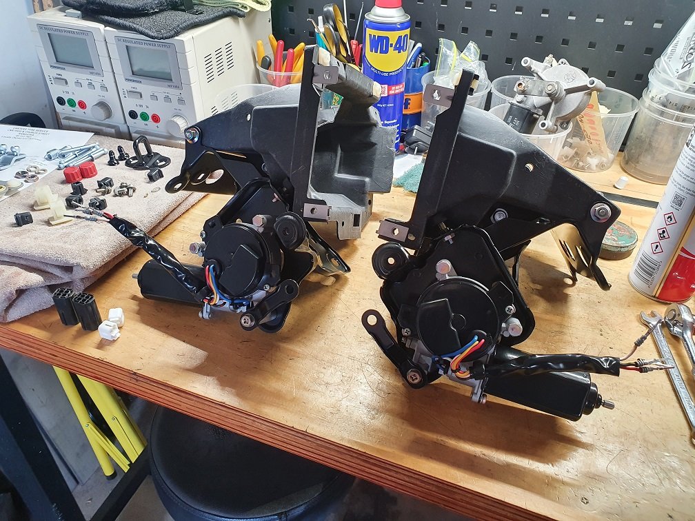
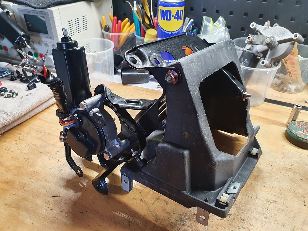
The headlight mechanisms on my car are a bit of a mess. They work, they're straight, but they are caked in red and clear overspray, really bloody ugly. Picked up another set for pretty cheap, and well, you know the deal by now... strip, repair, clean, blast, plate, coat...
The motors were kind of interesting to get back together... They were really tight on reassembly, like completely jammed. I'd paint stripped and powder coated the cases (didn't blast, as didn't want to deal with grit in there), so couldn't see why they'd be tight on reassembly. I'm thinking maybe baking the powder (215 degC) might have burned any residual oil in the bushings at the end of the case, and made some sort of hard film? Honestly, I'm at a little bit of a loss as to why. In any case, some time with rolled up 600grit sandpaper and the drill made the clearance needed to get them assembled cleanly again. All tested and working as they should. I'm a little worried they're going to work at different speeds, but can play with that later when they're fitted to the car. One of the connectors had a broken pin retention tine, so might just swap them out for DTMs. Will need to sort out the end stop adjustments also, but just put them back together as they came apart for now.
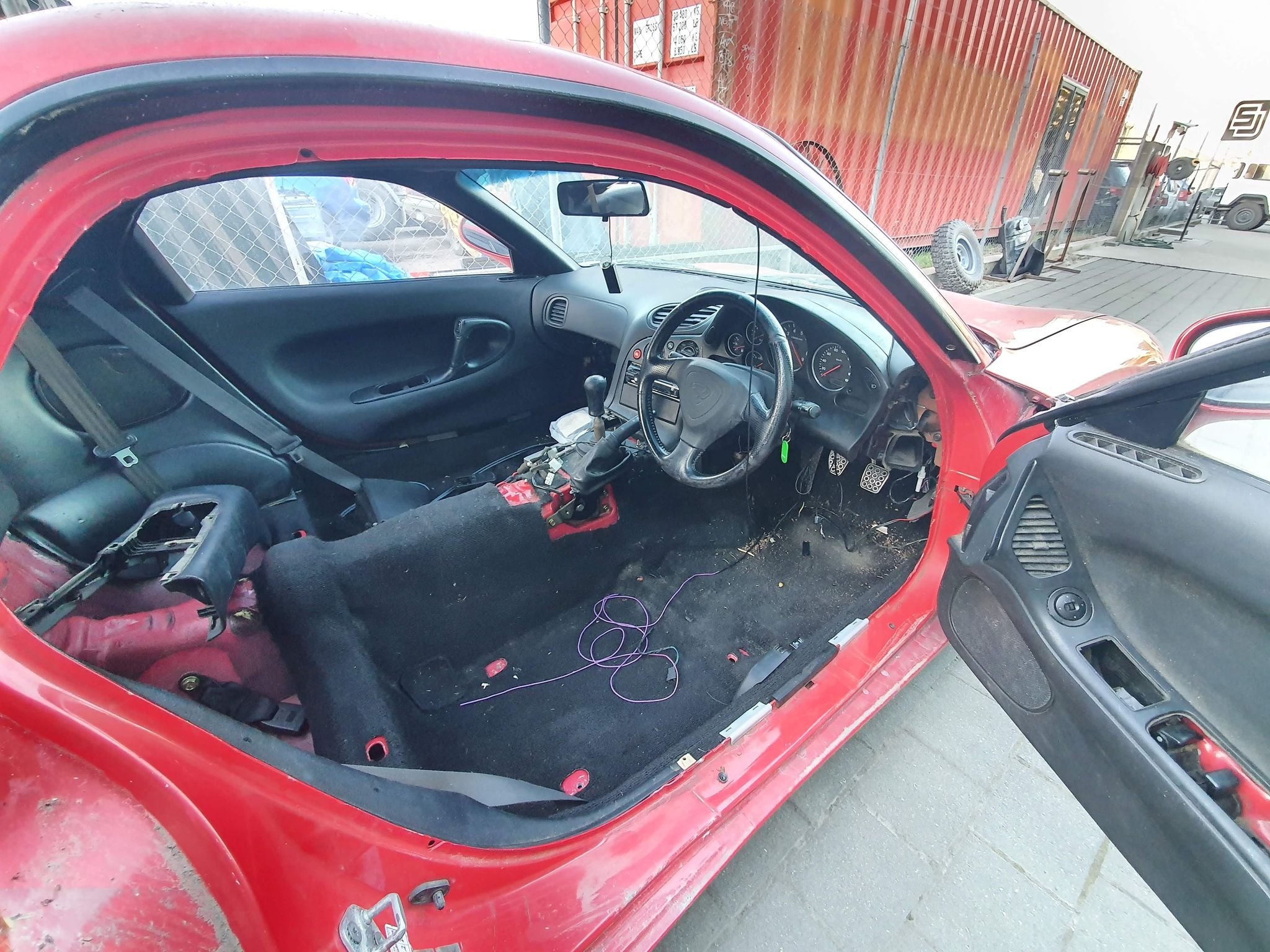
Interior rebuild continues. It's dangerously close to being complete even! For reference, this is what I was starting with:
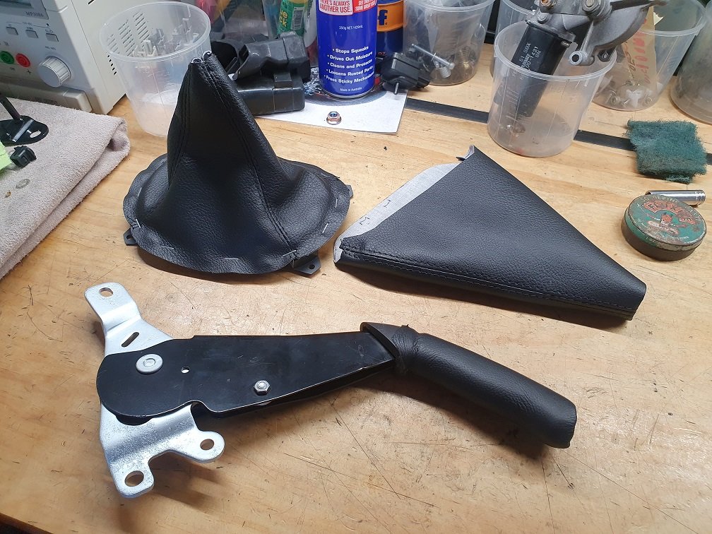
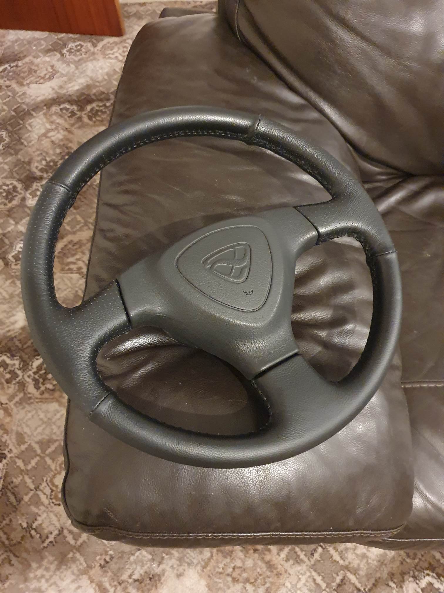
I got another handbrake handle assembly and stripped it down, repaired some sloppy-ness (made new pivots) and got it all back together. Dropped that and the steering wheel to a local upholsterer, along with the old gear shift and handbrake boots to copy as well. Handbrake handle looks excellent. Need to turn up another button for the end, there is some black delrin at work that I can pinch an offcut off. Seams in the steering wheel are a little lumpier than I'd like, but overall its a massive improvement! Nice leather, and managed to find some perforated stuff too to match the original way it was done. I've got a boss-kit and am always looking out for nice steering wheels, so I'll likely run a few different aftermarket wheels on this from time to time, but its nice to have the original one all tidied up again.
Lots of other ***** up in the air with it, a little scatterbrained at the moment to be honest, need to just tick some jobs off the list and re-focus.
There seems to be tons of replacement ***** for the handbrake on Buyee/Yaj.
Those OEM steering wheels are attracting high prices on YAJ.
The late 1995 airbagless steering wheel for the first version 4s is rare and attractive. The following wheel is also attractive and selling for about C$250 on YAJ.
I have gone with the wood Nardi wheel from the Miata. It feels like the bakelite steering wheels from the 1950s/1960s.
There is matching wood handbrake and shift ****.
I think it very likely that your new leather skin will settle in and will be great to have for a long time.
Yeah, I saw the replacement covers on YahooJapan, but didn't like that they're meant to just slip over the original by the look of it. There was actually a heap of work into that handbrake handle, including cutting off the original rubber grip, total disassembly, blasting, plating, turning up new pivots, filing the ratchet pawl to make it engage nicely... Had to 3dprint a bushing to slip in to take up the side to side play in the button, reassemble and then glue the rubber grip back into place. Yikes. I kept the original leather covering from it, and I suspect he used that as a template, but now its nice new soft leather, without the years and years of finger juice ingrained into it. Ew.
Yeah, I had another OEM wheel that was in arguably better condition, sold it to a guy with an FD he's bringing back to life up the other end of NZ. Sold it cheap because he seems like a good dude, doing the good work to revive a car that needs it! I hope you're right about the seams, I can always get it re-done in the future, maybe cut channels into the rubber beneath for the seams to sit into or something.
How difficult was it to find someone to recover the shift **** and ebrake handle? I had a hard time finding someone to do mine last year.
I had a Starion a few years back I wanted the seats reupholstered in, I approached a few local commercial shops, and they gave me 'F Off' prices... then heard about a local guy doing work as a side hustle. Was still expensive, but worth every penny, his work was top-notch. For the steering wheel and handbrake handle in leather, and boots for both in vinyl it was $350NZD, which I was more than happy to pay :-). I purchased a new OEM gearshift ****, and the match is spot on :-).
I started building the wiring harness this thing actually needs!
Sooooo, let me immediately pivot and tell you a story of ECU's and their mounts.
I've got 3 ECU's planned for this thing.
To get the thing fired up, leak checked, heat cycled, maybe a couple of drives around I've got a stock super early S6 8bit POS ECU. I've actually got a couple, once with a case and one without.
To drive the thing a little longer term, and maybe get a little more jam out of it I've got a Power FC. yes, I can *hear* the eye-rolls, they're antiquated, old, past their used-by, and all that... But, TBH, that still work just fine in a pretty mild setup. Add to this that I've got (borrowed, as they seem to be genuinely hard to buy?) a datalogit to go with it, and there is still pretty active development around tuning these, I should be able to get the thing going pretty well on this :-).
In its final form though, I want an e-throttle on it, and I've had a Link Fury kicking around on the shelf for a couple of years, so this will find its way in here. This also has the benefit of a built in wideband controller. I don't really like external wideband controllers that rely on analogue voltages :-/.\
I only want to build one wiring harness for the thing though, so it has to cater for all three conditions. This has driven the design of a harness that uses the original style of connectors at the ECU end, but also quite a few 'auxiliary' connectors in the cabin to cater for mods and the different installations. When I stated building the harness, it was pretty clear that I really, really needed to know where these connectors were going to be mounted. I contemplated just eyeballing it, but know I'd be annoyed later...
So, needed to mount all this crap, for all the configurations! Obviously the stock ECU is easy, it just bolts in. Its mounts are actually a little hacked up, but as I'm not going to keep it in there long, eeeeehhhh, its fine. Having this is pretty crucial though, as it let me see how much space is under the passengers kick panel there for mounting all sort of crap. Pleasingly, and quite uncommonly IME, there is actually a heap of space!
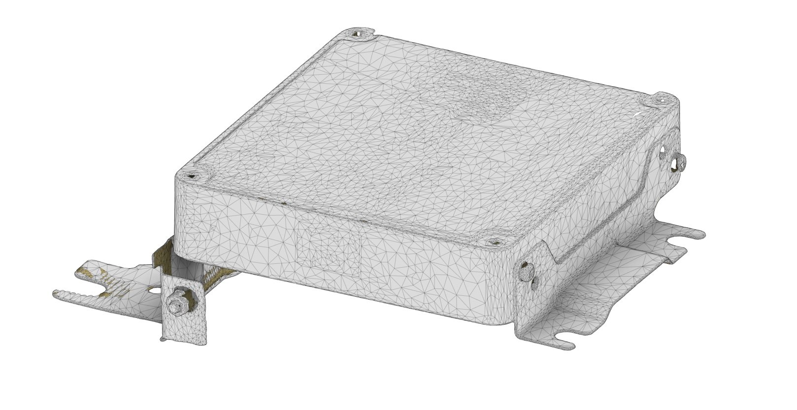
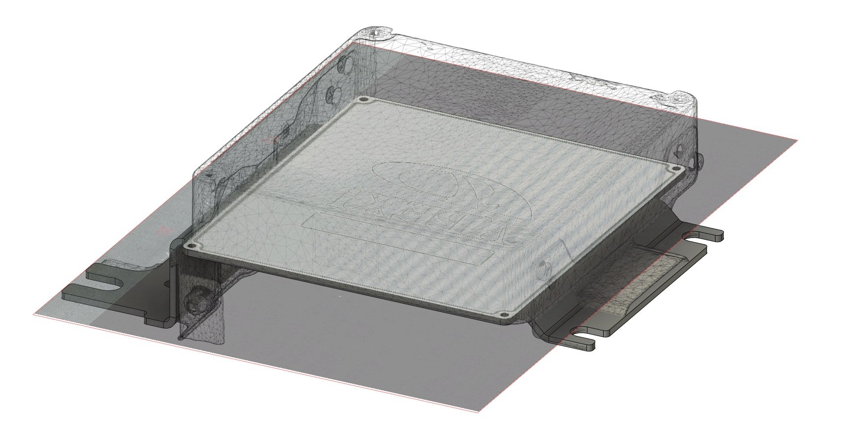
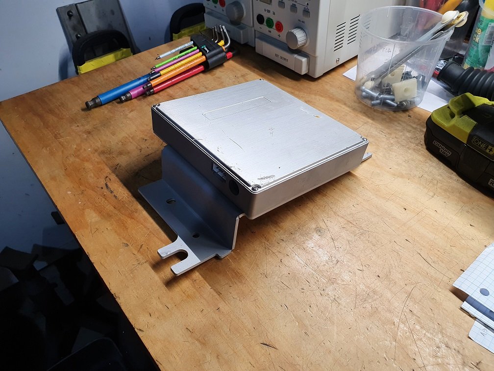
I scanned the OEM ECU, got a decent mesh out, aligned it in CAD and used it to get the mount point locations. This let me CAD up mounting plates for both the Power FC and the Link Fury. I went a little ham-spec on the Link Fury mount, as its the final one the car will end up with, so should be a nice piece of kit. The Power FC one is a little more 'thrown together', but still tidy enough.
Low res version of the scan of the original ECU.
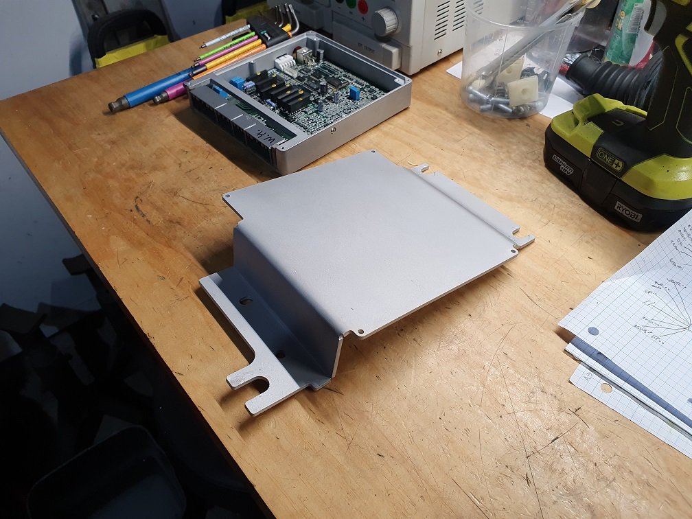
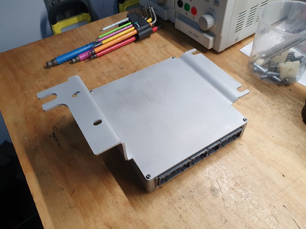
Combined with a 2D scan of the power FC backing plate, and a sheet metal replacement modelled up. Quick and dirty. It *just* fit within the work area of the water jet at work (its a baby). Cut it out, folded it up, and screwed it in place of the original ECU cover.
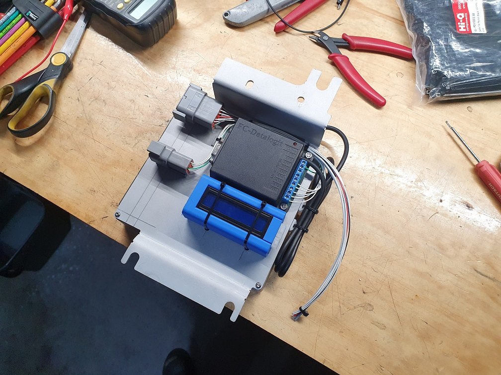
After a quick test fit, its a go-er. There is heaps of space on the other side of the new mount for other items too, like the datalogit, and wideband controller. Bit of jiggery-pokery to get everything lined up, drill a few holes...
Waiting on the molex connectors for the wideband (14point7 SLC Free 2) to show up so I can finish the wiring. Not worried about the display on it being totally hidden as it'll send its linear output to the datalogit where I can view it on the laptop, and its simulated narrowband output back to the OEM ecu or Power FC via their main connectors.
The trim even still fits! Score! ;-). 100% going to have to get/make a torch to go in the holder that looks like an original flare.
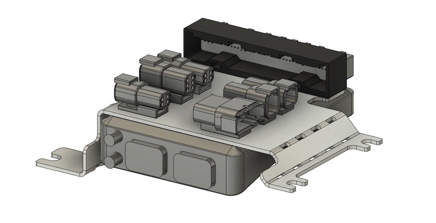
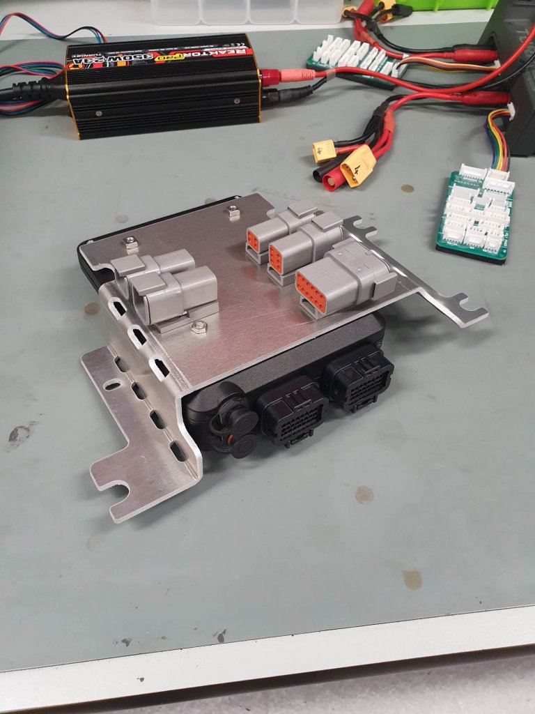
Right.... One aftermarket ECU down, the other one to go! Little bit more thought involved for this, I wanted to integrate an OEM connector body onto the ECU mount, along with all the auxiliary connections for additional sensors, e throttle, accel pedal, CAN, and the rest. It's kind of a plug-in adaptor and mount all rolled in together.
This is what I came up with. I bought an OEM connector housing, and have trimmed the pins (they're only available in a PCB mount version). Have designed and 3d-printed a backshell, and after the wires are soldered to the pins the whole thing will be potted with RT125 or similar.
This one actually too two tries, ECU wasn't high enough to clear that plastic wiring channel the first time. Second time was a charm though, and the trim still fits! Have done the wiring design on this... Actually doing the physical wiring on it will be kind of a chore, there is quite a bit too it. Worth it for a nice solid solution though :-). Will start of the wiring of that tomorrow I think, atleast do all the power supply, CAN and any shielded stuff on it what requires annoying splices.
Soooooo, I can get to building the actual harness... ummm, soon? Honestly, excited about it :-).
That's fantastic! Will the LINK be flipped the opposite direction so the connectors can plug in from the firewall, or do they need to be facing toward the interior like that?
That's fantastic! Will the LINK be flipped the opposite direction so the connectors can plug in from the firewall, or do they need to be facing toward the interior like that?
The link ECU will be wired to the DTM connectors, and OEM connector body on the other side of the mount, all the connections to it are made through these. Makes swapping things in and out easier, and means I only need to build the main engine wiring harness once, and hopefully not modify it down the line when I want to change things around (I've totally just shot myself in the foot, writing that, hah).
Months go past, and alas little work done on this thing... Lots of family visiting, really busy with work, usual life stuff, you know the drill I'm sure. I have been tinkering away a little though.
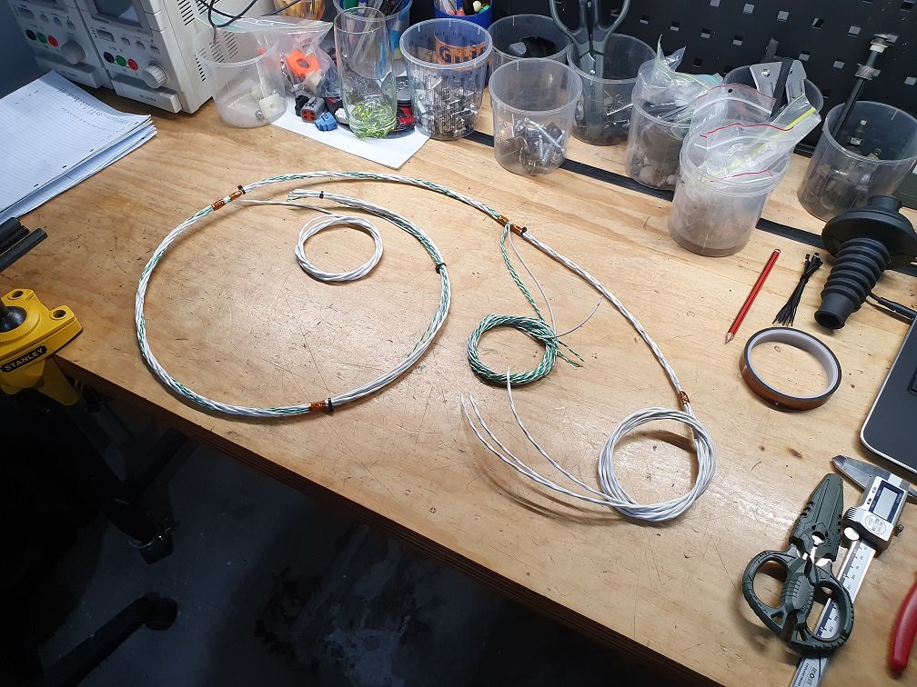
I've built the starting and charging harness, the two times I've ordered the correct pins for larger contacts in the two grey connectors by the strut tower they haven't shown up, so I gave up and have swapped them to a DTM12 and DTP4. I moved some stuff around a bit so the connectors for the aircon clutch, power steering pressure sensor and oil level switch are now in the main engine harness, so the starting and charging harness interfaces with this by a single DTM6, keeps things a bit cleaner. Now, the main engine harness... I've done a heap of work on this, but there is still a bit to go. It's designed to work with a factory ECU, a power FC, or the link fury I have. Its future proofed for modifications like another turbo control system and e-throttle. Its made out of the good stuff, M22759/32 wire, twisted, DR25 sheathed, etc. I don't want to have to build another one!
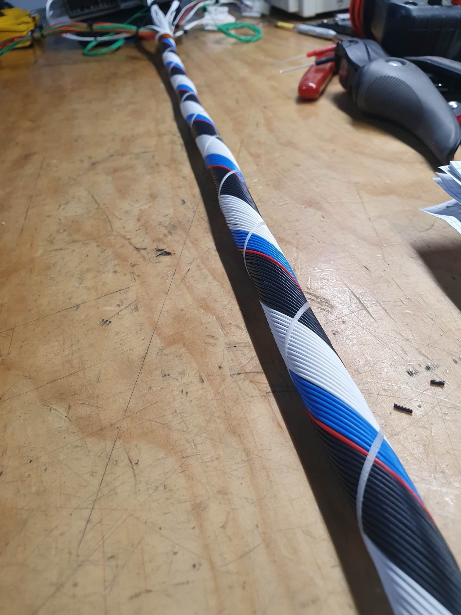
After some basic measuring and figuring of branch point locations, I put the core together, this is the shielded wiring for the engine position sensors, knock sensor, gearbox output speed sensor and O2 sensor, aswell as a couple of unshielded twisted pair runs for CAN.
Many hours of work later, and another three layers of 22AWG:
This is the run from the interior breakout by the ECU, through the firewall, to a branch just by the oil filter pedestal, where the UIM interface connector will be, the gearbox wiring, oil pressure and water temp gauge wiring, as well as an aftermarket combined oil pressure and temp sensor.
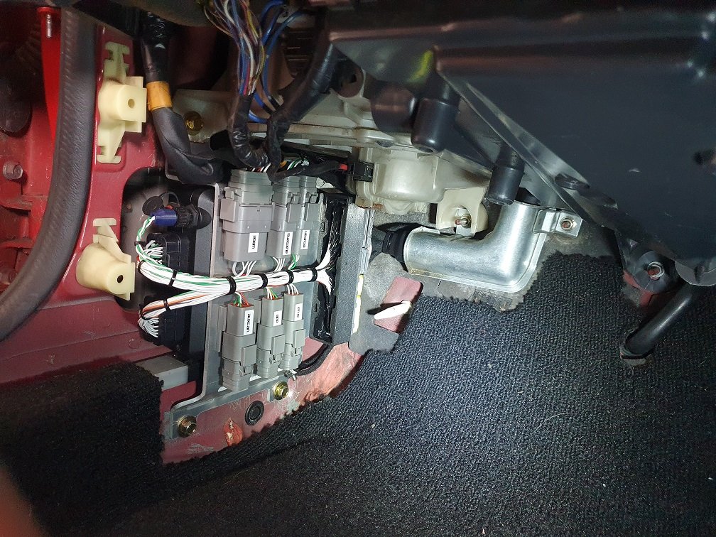
After sheathing this section in DR25, I fabric tap wrapped the breakouts at the ECU end. Fabric tape is awesome in interior sections, as it stops rattles :-). I printed a mid-shell to house the splices and wire turn-arounds, keeping them protected, and making the transition between the DR25 and the fabric wrapped breakouts nice and tidy. No need to boot and pot this interior stuff.
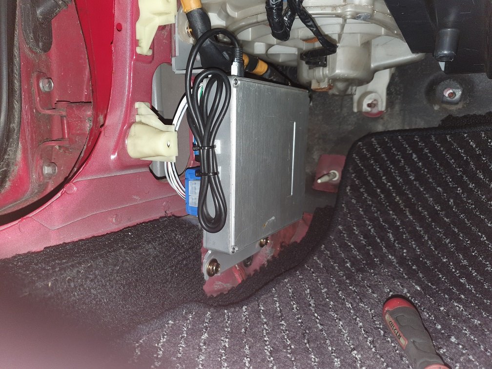
Can see the Link ECU mount all finished and wired up there too. There was a bit of test fitting along the way, but got it fully plugged in with the OEM trim and cable protector this morning for the first time.
Hmmm, satisfying.
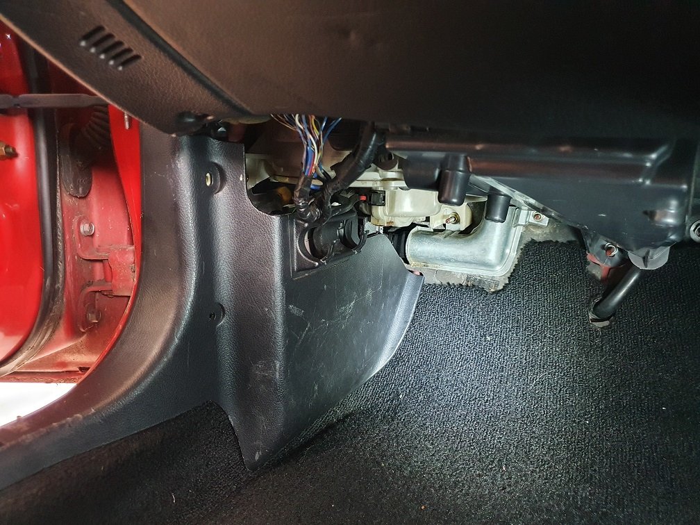
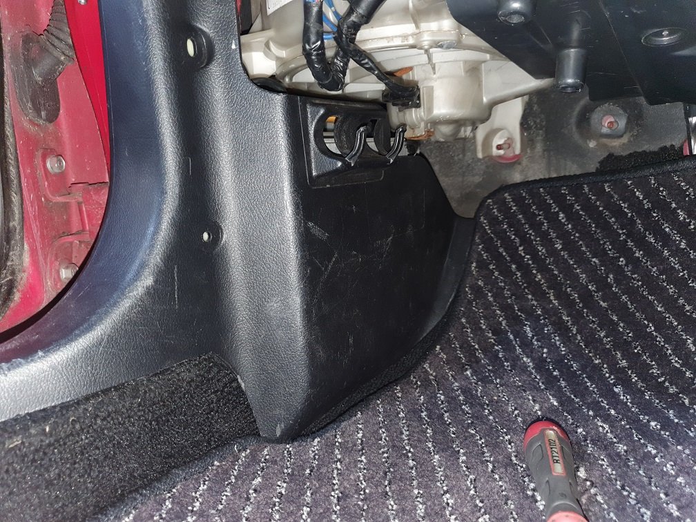
And then hide it all away!
I still have all the engine bay side to do, organising the other three branch points, sheathing the main runs, putting the boots in place, sheathing the branches terming and then potting it all up... You know, not much work at all! Total overkill for a mildly modified street car, but its work I'm familiar with and enjoy, and I've never actually built a ham-spec harness for one of my own projects before, so it'll be nice to have one. Most of the materials are left-over from projects over the last few years, so its not been a massive financial burden... time wise though? yikes.
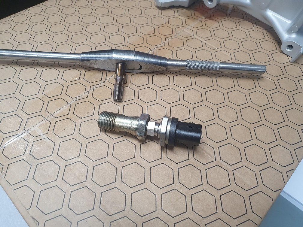
For the aftermarket oil pressure and temp sensor, I drilled and tapped the banjo bolt that connects the oil coolers to the filter pedestal. This should work well, and means I don't need to buy an aftermarket pedestal or anything, but it does put the connector for the sensor annoyingly close to the heater pip in that area. Clears, but not by as much as I'd like.
Tapped it to 1/8NPT, and used a M10x1 adaptor with the correct seat for the sensor. About as compact as I could get it. Even did it on a lathe so its nice and straight :-).
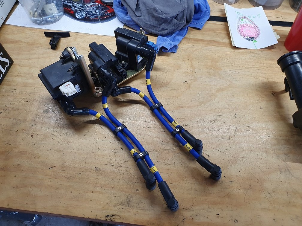
When building the starting and charging harness I made up some ignition leads as well
They're tight to the oil filler neck, but everything clears and they're a bit tidier than then OEM ones. Separators are printed in PETG, will see how they hold up.
Might have it running by Christmas? Yeah, nah, probably not, but no rush eh? :-).
Its been a... year. And I mean that it is both surprising that a whole year has passed, but also not, because it passed in the blink of an eye, because it was a _year_. Lots of things non car-related happened, less things car related happened. I still tinkered in the garage though, as it was excellent therapy time :-). No, it still doesn't run. No its not any closer. Yes, I worked on things that get it no closer to running and driving. Yes, I enjoyed it. No, I don't have a timeframe, not what its about :-).
Some highlights:
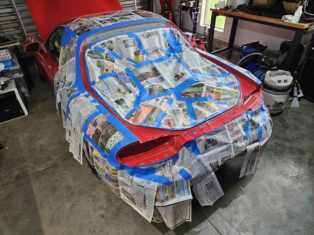
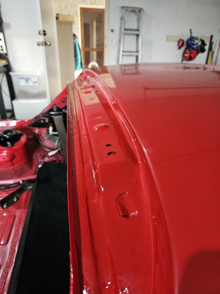
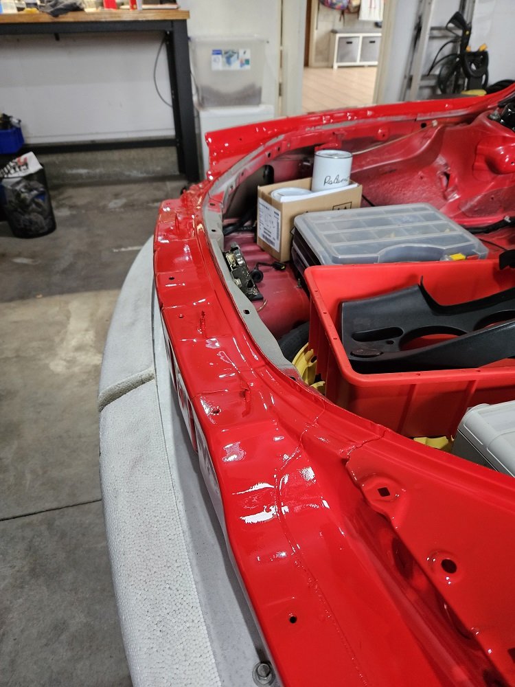
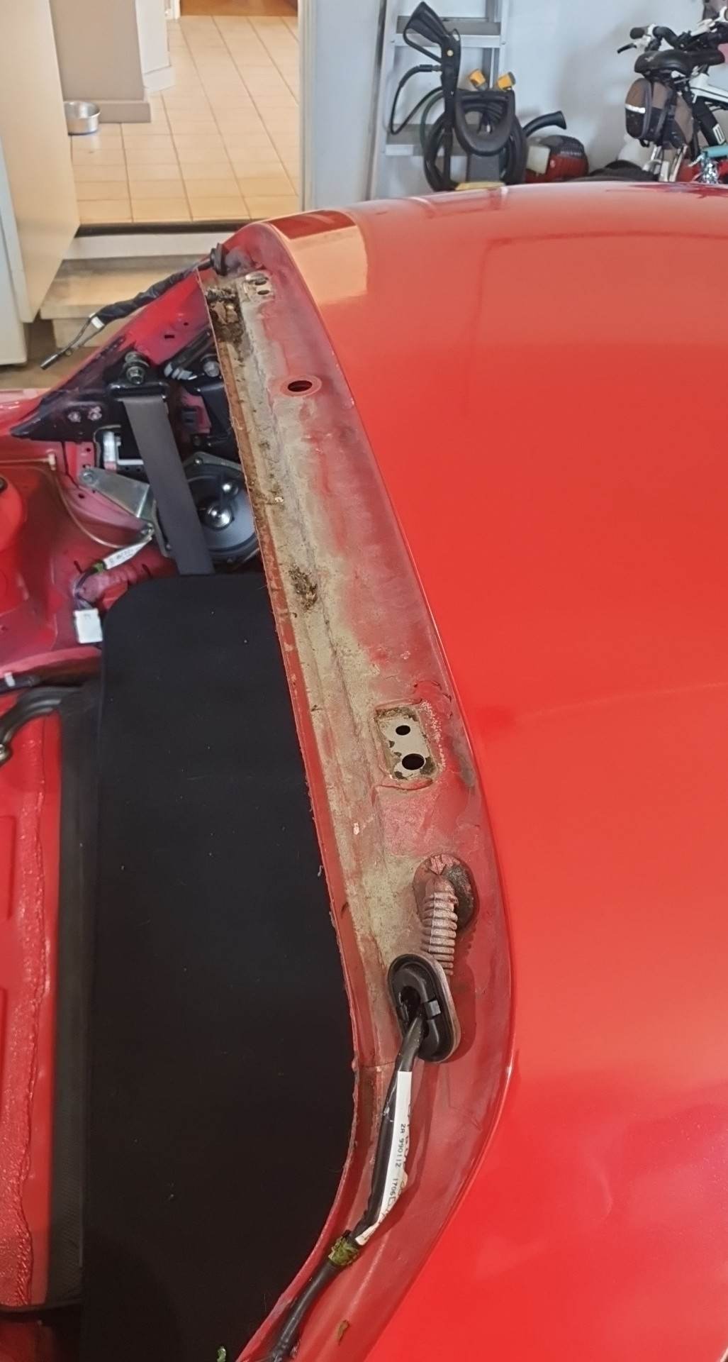
I took the boot lid off because I couldn't get up in there to clean with it on. Overspray all over the wiring boots, grimy, all caked up with the clearcoat, some surface rust here and there, nothing that some scotchbright and etch primer wouldn't fix.
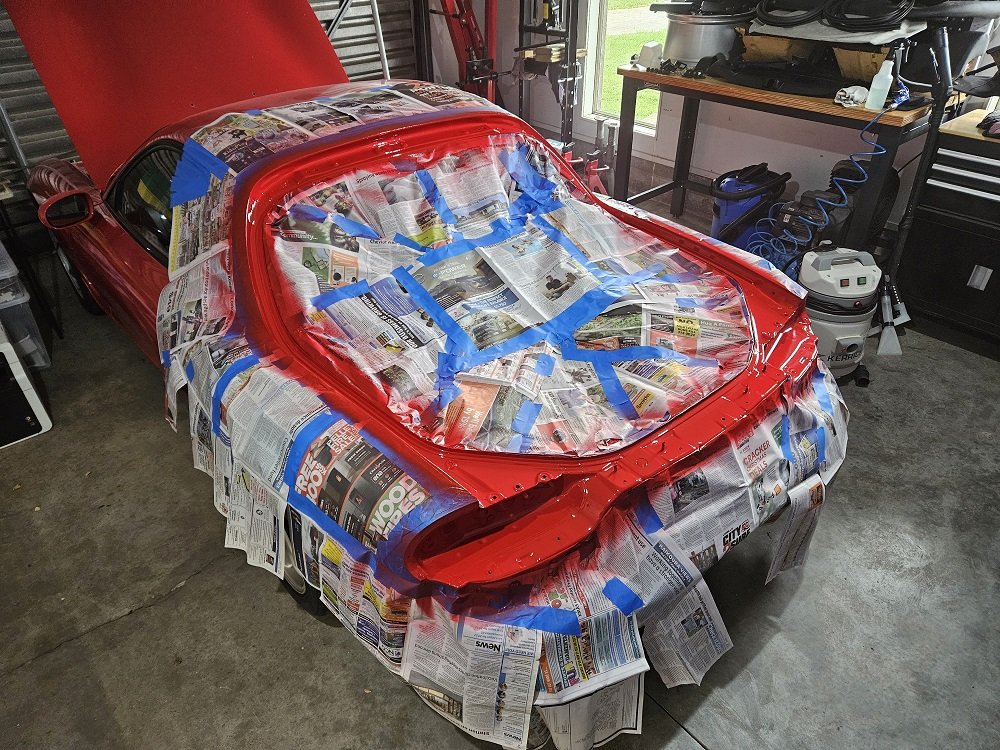
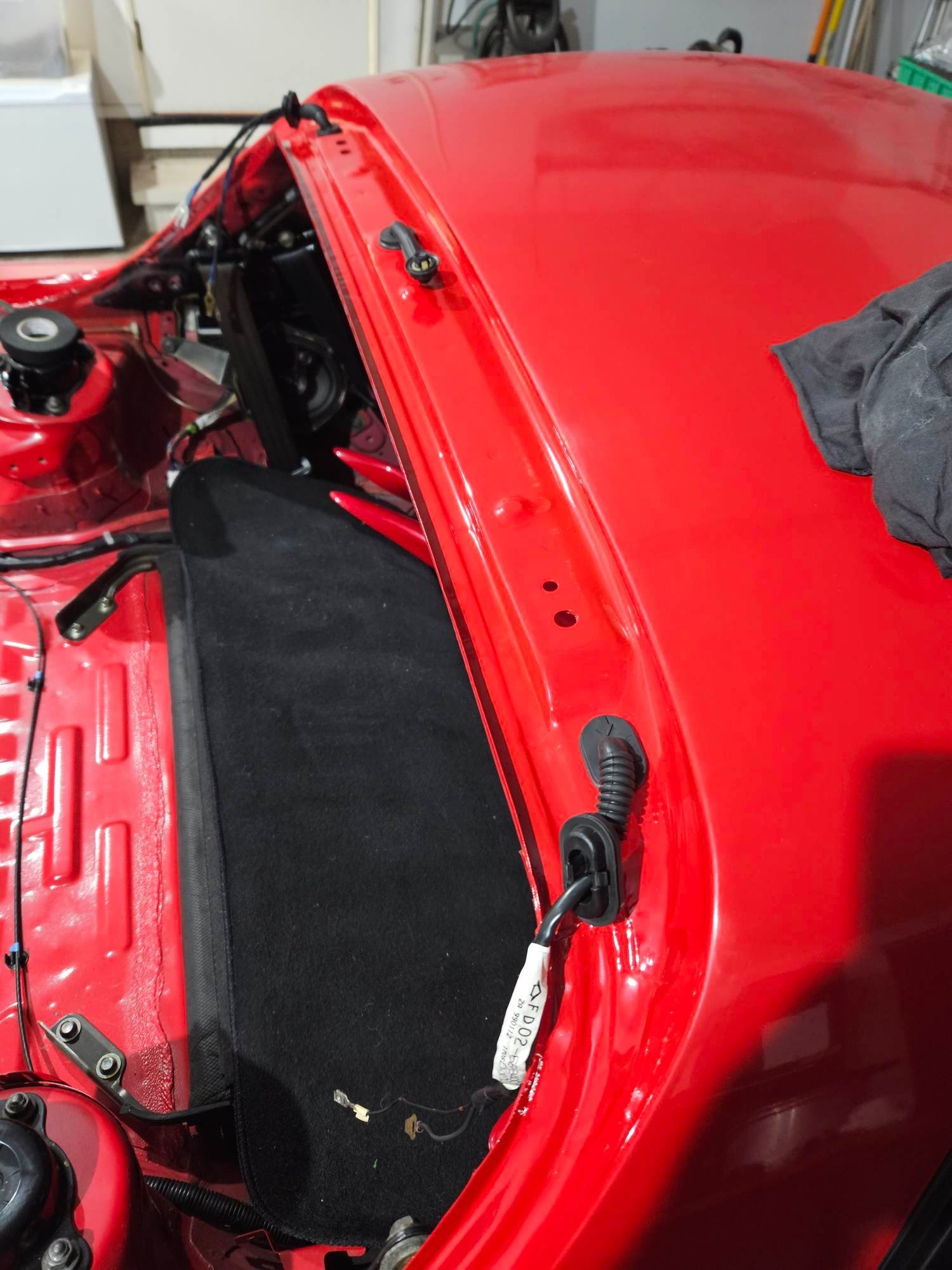
Back to back I think the contrast is quite satisfying... Yes, I painted the jam. Removed the rubber boots / washer hose and vaporblasted all the overspray off them, they look brand new now :-). Have cut some rubber gaskets to go around the hatch hinge studs to do the job of the seam sealer that was used from factory. It's not like I'll be driving the thing in the rain much.
Process photos:
Cleaned the jam thoroughly, then roughed up with grey scotchbright. Sprayed etch primer on the parts that were missing paint up under the top of the hatch.
Ordered some 2k paint from a place in NZ. They pre-mix a slow hardener in, put it in a spray can and courier it. Has about a week of pot-life apparently. Worked excellently, no reactions, good coverage.
Did 3 coats, then sprayed some into the lid to go around and do touch-ups on various chips and stuff. I'll end up doing all the jams, and probably the bay like this myself, then one day It'll get a door shut respray by someone a little more into body work than I. Made it look a heap tidier in the mean time.
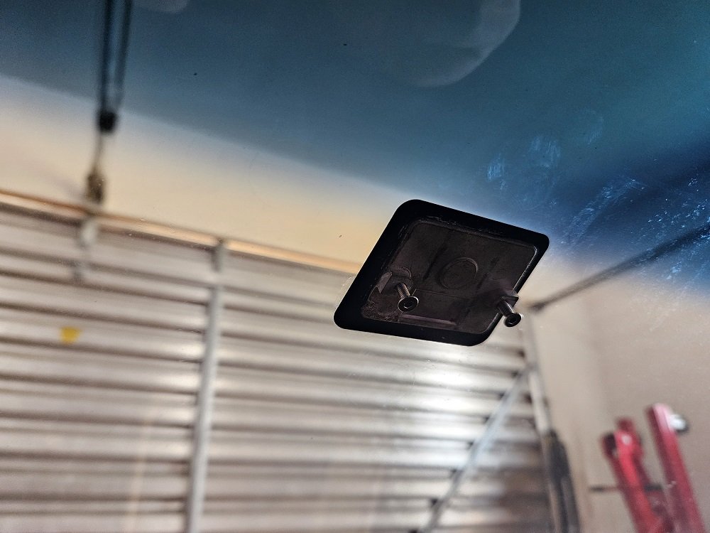
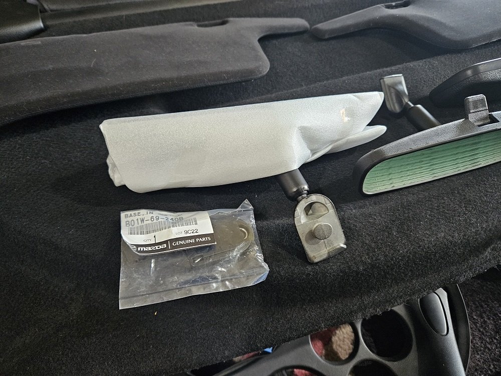
Back into the interior, the rear-view mirror was all delaminating / corroding around the edge like they do. As this is a super early car it has the early style mirror... I didn't realise there were different types when I bought a new replacement mirror from Mazda.... Well... I figured I should swap to the newer style, as if I ever need a replacement windscreen they are way, way more common. This meant I had to remove the mirror mount that was glued to the screen... This puppy:
I popped a couple of screws in there to give me something to grab, but it was on there solid (which is a good thing). I read about removing them, and it seems that heat is the key. I went gently gently with the heatgun... heating from the outside.... This was wrong and got me nowhere. After turning my heatgun from 'kitten breath' to 'dragon flame' (the only two settings is has), I heated the ever loving crap out of it from the inside... I mean got it properly hot... I gave it a tweak with the pliers and it fell right off, into the wet rag I had right below it... where it sizzled and steamed. I read horror stories of people dropping them, where they then melted the dash and carpet.... No thanks.
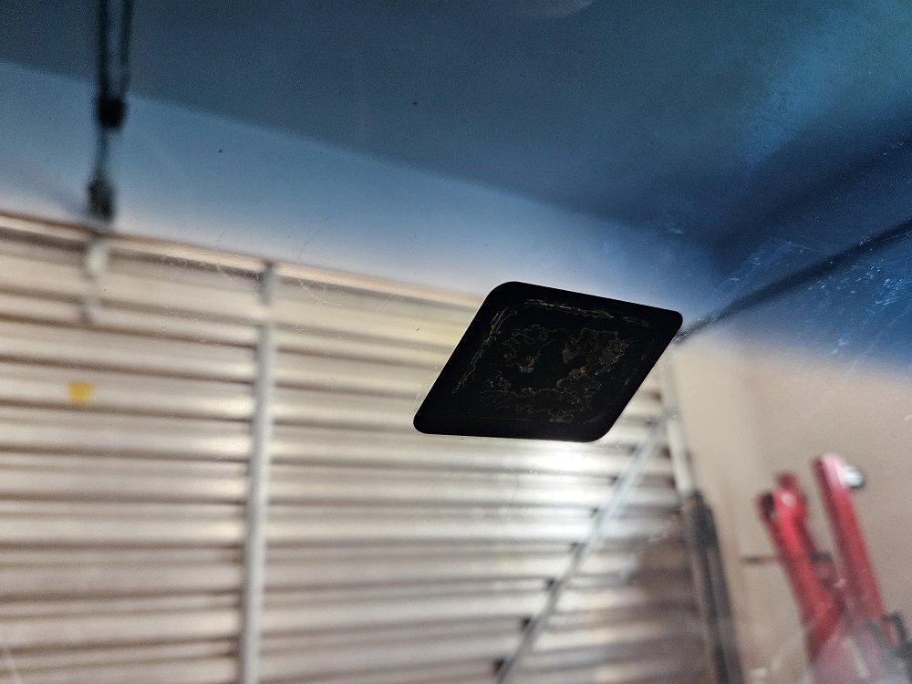
I got most of the residue glue off with solvents and careful scraping. Its some sort of bonded on ceramic pad on the windscreen I'm pretty sure, I was scared I'd scratch it and you'd be able to see the scratch from the outside. No chance of that, the black portion is very, very hard.
Have got the later style button and the correct Loctite adhesive to bond it on, but haven't done it yet as I need to come up with a plan to get it perfectly in the right place, or it'll drive me nuts every time I look at it.
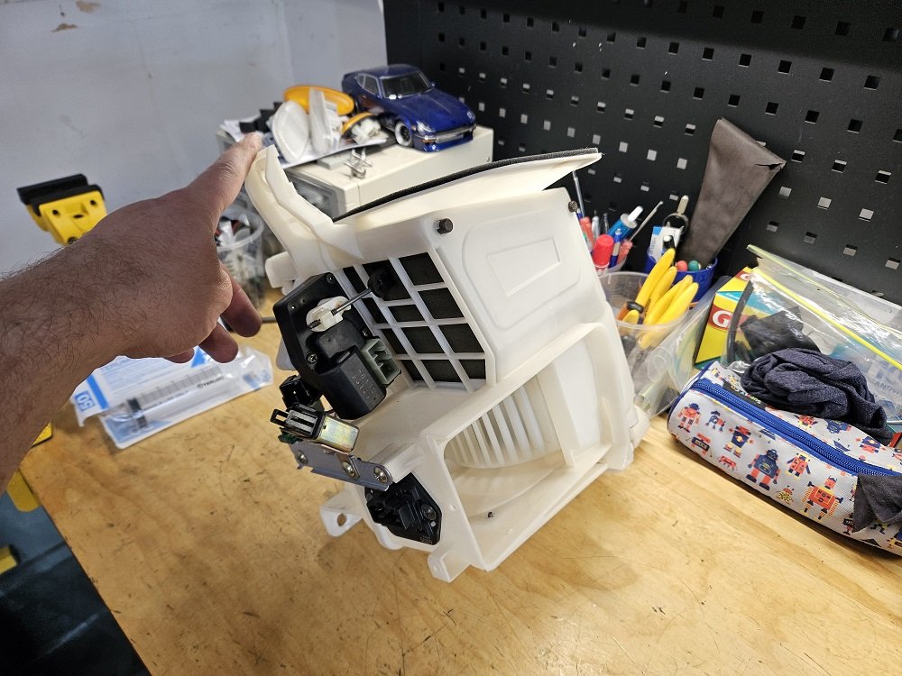
During my experiments with powering up the electronics in the car, I played with the HVAC system a bit. It all seemed to work as it should, but it was kind of noisy, and the blower motor sounded terrible.. I'm sure you can see where this is going.. Rejuvenation time!
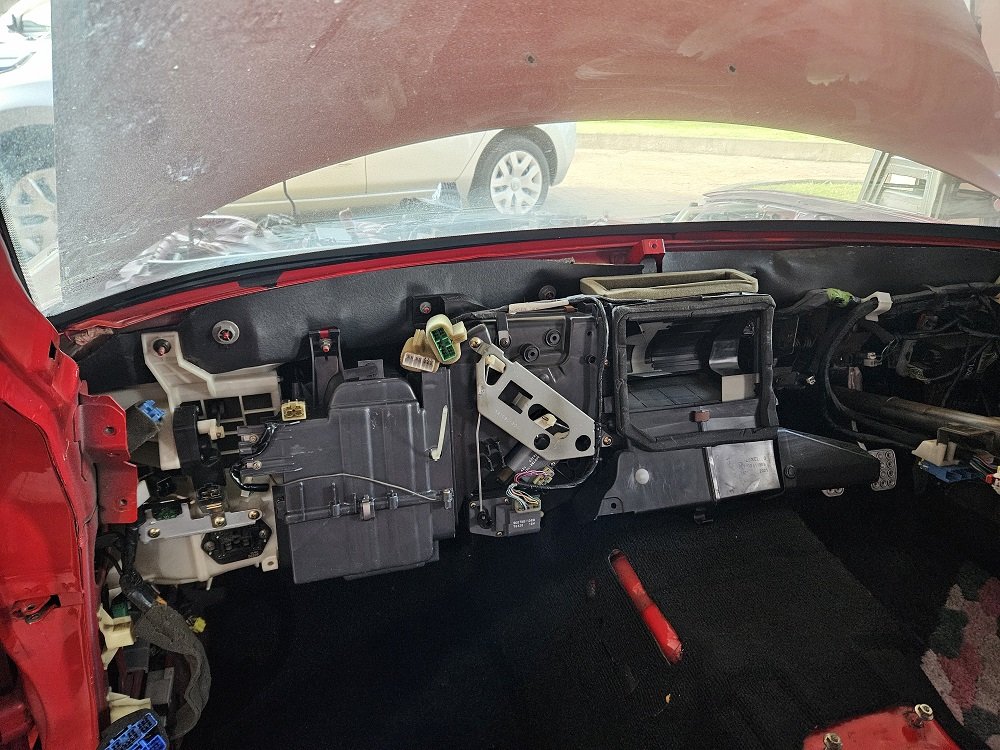
Turns out you can remove the A/C evaporator and blower motor without pulling the dash, its not even that hard... but the distribution / mixer / heatercore box is right in the middle... So I pulled the dash. I was expecting a headache, but genuinely the easiest dash I've pulled out of any car, was pleasantly surprised! I'm super lucky that the dash in this car is in very good condition (see the original interior photo, its the only part that IS), so its stored safely inside on the spare bed :-). Will need one repair to a plastic mount where the glovebox screws in, but basically all FD dashes are broken there. Will glue the cracked bit up, and come up with some sort of 3d-printed reinforcement I reckon, to stop it happening again.
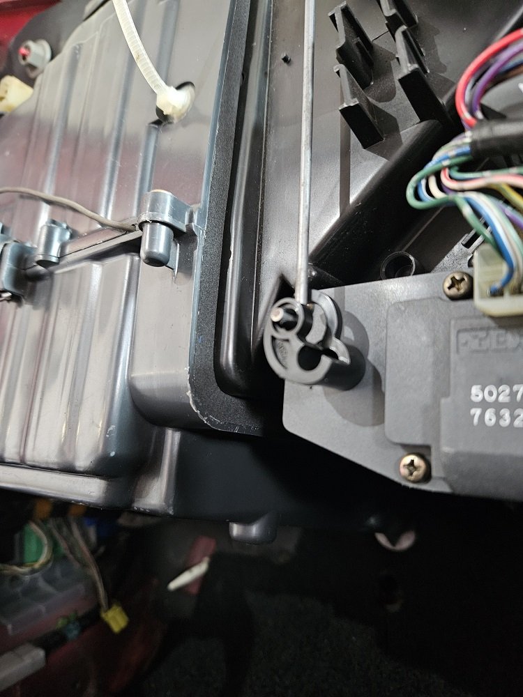
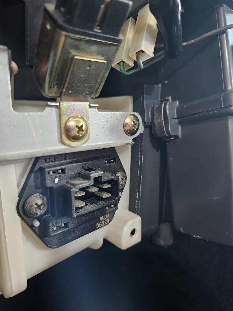
Pulled this completely apart.. The DC motors that drive the blowers are pretty grunty.. The original one from the car was particularly nasty too. Brushes still looked okay, but the casing was a bit corroded, and it was packed full of leaves, dust, feathers, grime, your mothers underwear, shells, nuts... everything. I had a spare blower motor, so yanked the motor from that as it was a much cleaner unit. Still pulled it apart, tickled up the commutator and brushes, re-lubed everything... the usual. The plastic impeller and casings all got a low pressure vaporblast to bring them back to new. Took the recirculation door actuator apart, cleaned tested and re-lubed as well, tested the relay... all the things. Should be good to go :-).
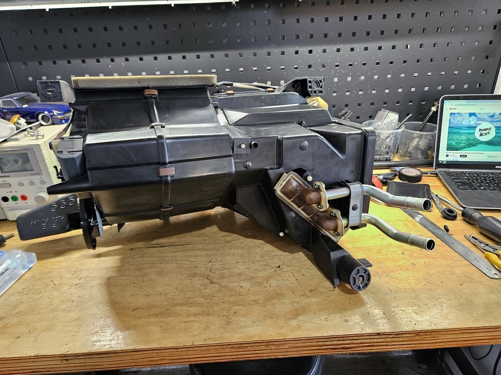
Gave the distribution box the same treatment. Although I cleaned this one in the sink, as the foam was actually still in really good condition so I didn't want to blast it off. The heater core pipes were in a really sorry state though. So pitted. Removed all the corrosion, made sure they were still nice and strong, blasted and had them plated. Reinstalled with new o-rings. Hope like hell they don't leak at the interface to the core, as that's a dash-out job to fix, but I reckon they'll be alright :-).
Dummy fitted this with the pipes loose so I could adjust them to be right in the middle of the holes in the firewall, have new pass through grommets on the way from Amayama.
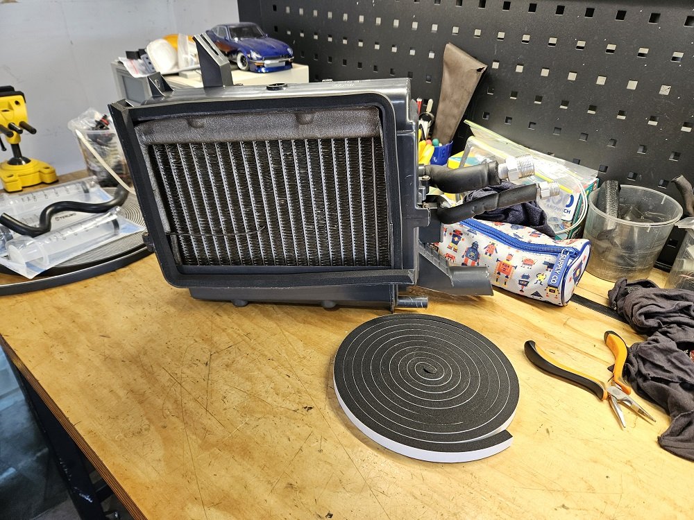
I will absolutely have AC in this car. As its an early one, it was fitted with an R12 system. I luckily managed to get most of an R134a system out of a later car a couple of years back, so gave all that a thorough tickle up. Looks to me like the actual evaporator cores are the same, just the expansion valve and its temperature probe are different. This R134a system is a 'Denso' style one, and has the metric threads on the attachment ports. I did a heap of research when I was playing with it as I'll have to buy fitting and make lines... Most of which I've forgotten now, but I don't remember it being complicated, so I'm sure I'll be able to figure it out again ;-). Have the R134a compressor too. Will roll and aftermarket condenser and dryer.
replaced the seals with some 12x9mm adhesive foam tape from para rubber, seems like it'll work well. I tried 12x6mm initially, but it wasn't thick enough. This compressed just a little as I tightened the unit down.
All back in place and looking nice and fresh. Smelling much better too :-).
Now for some truely barry-spec ****:
I'm not some kind of audiophile, but I did work at Repco for 10 years, so I'm good with cars, you know, doof doof?
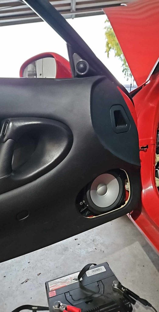
Speakers. The factory ones were shagged, and as I want to get the doors back together SOMETIME they need to be replaced which they're apart. I figured some nice alpine components would be the go, because a: Alpine is an excellent brand, and b: They were on spesh. I figured the little triangle on the front doors at the base of the A-pillar would be a damn fine spot for the tweeters... so went full ham and overcomplicated things.
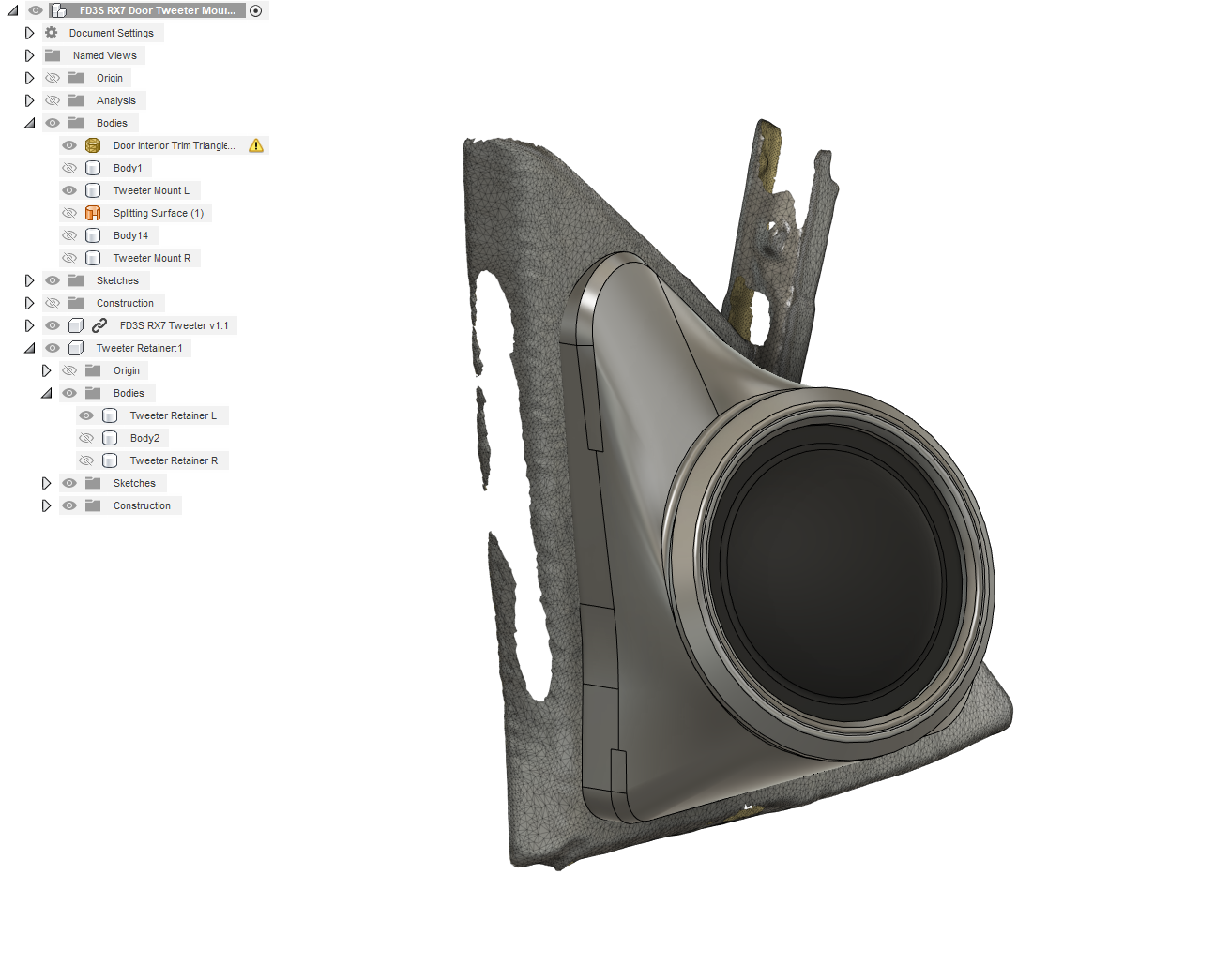
Took a quick and dirty 3d scan of one of the trims, used it as a guide to model the surface (its annoyingly compound in 2 directions). Then played around the in car and figured out how to angle the tweeter.. put it in the model where it needed to be, and generated a mount to keep it there. Used the modelled surface to trim the back side to its a good match, put in some fastening and retaining details, and 3d-printed. This was actually a ball ache, and there were a few iterations... But, this is the **** I love, so I had a good time doing it.
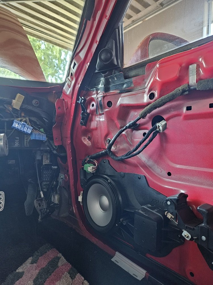
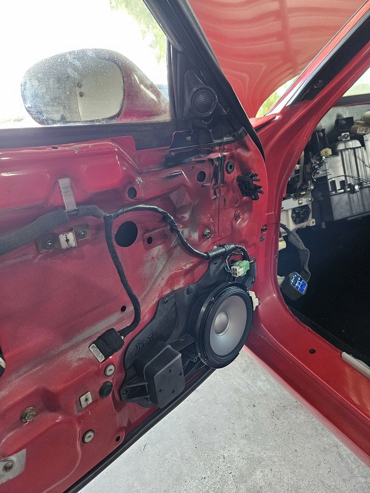
Once that was done I figured getting the 6.5" drivers into the stock speaker locations would be a piece of cake, as its a round speaker into a round hole, and there is always a couple of cm of clearance here and there to play with... Nope! I mean, it wasn't *that* bad, but there is less and a mm of clearance at the back to the glass when the window is down, and the grill in the front when the door car is in place.. so still a bit of a ballache. 3d printed some adaptors, the two major circles of which are NOT concentric, because of those clearance issues. This got them nicely in place. The crossover is mounted to the back of the original speaker housing, as well as a DTM 2-pin the tweeter plugs in through, so all the original wiring can be retained, don't need to run anything extra out to the doors.
Quite a bit of work for a stereo that will probably never get used for anything except phone calls.
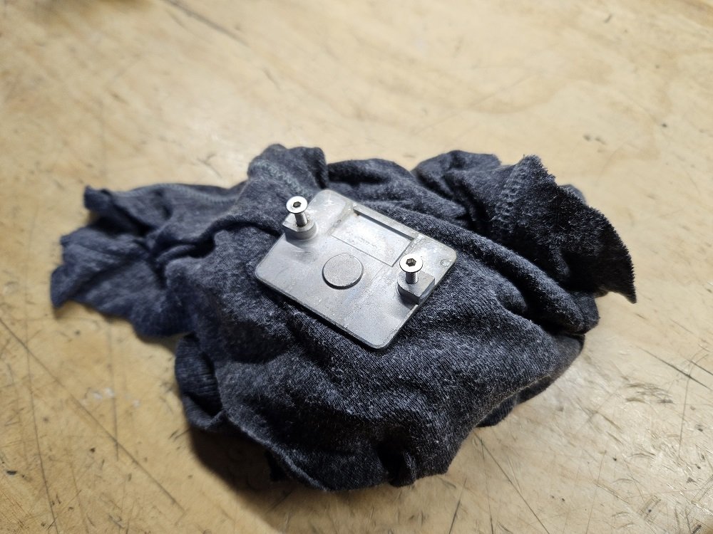
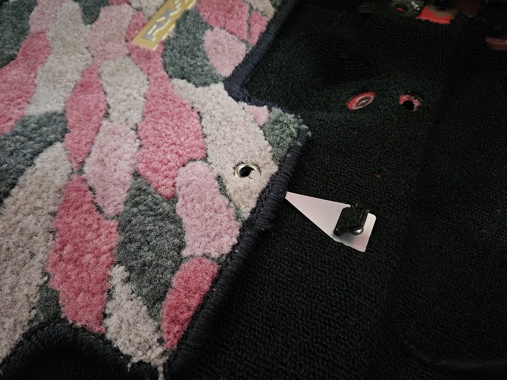
And, final little useless detail that I snapped a photo of... I was missing the floor mat retainer, and I didn't really like the original design. So, sheet metal CAD, water jet some 1.5mm stainless, bend, vaporblast, and voila:
No, I don't want to cut the little flap of carpet off. Can't see it once the seat is in there :-).
Should really finish off that engine bay harness! Yeah. Nah, Maybe. Having fun though :-).


.thumb.jpg.b3b24bc64011b653edea363649a1b871.jpg)

.jpg.cc53569bcc9f2767aec312ffa3a1b400.jpg)