When you click on links to various merchants on this site and make a purchase, this can result in this site earning a commission. Affiliate programs and affiliations include, but are not limited to, the eBay Partner Network.
I have been working on important engine things, honest! Part of that has been getting all the gaskets sorted, making emissions block off plates, re-kitting the injectors and manifolds... etc, etc. Will tidy all that up and post about it.
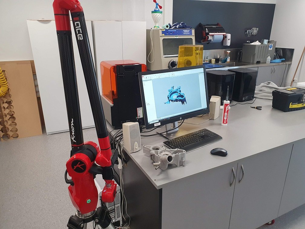
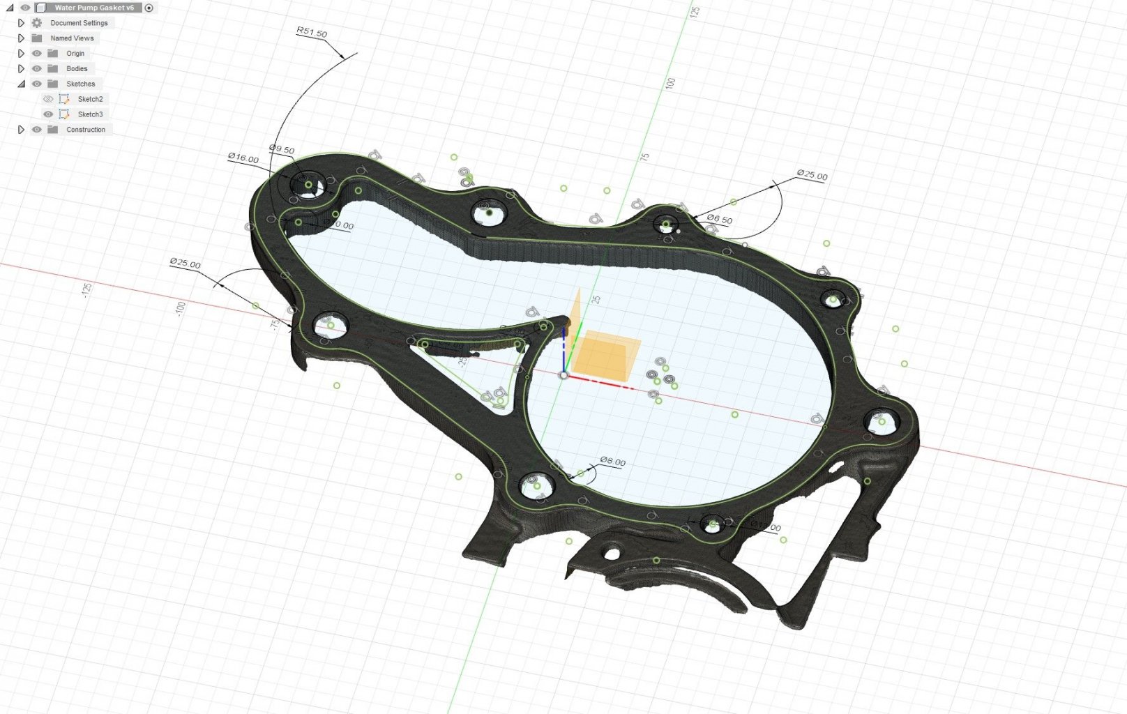
Nothing like using a 6 figure bit of gear to make a $3 gasket though... Usually I just use a flat bed scanner, with a ruler in the frame as well for scale, but this wont lie flat on the scanner.
Some CAD:
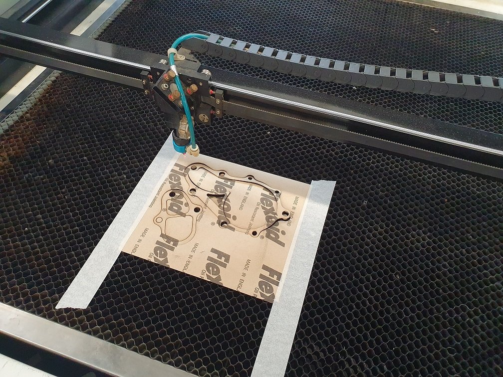
And the laser cutter. I've cut all the other gaskets I need basically the same way so I don't have to nickel and dime around waiting for them to arrive. Plenty of ways to skin this cat, but I've got access to the gear, so may as well use it.
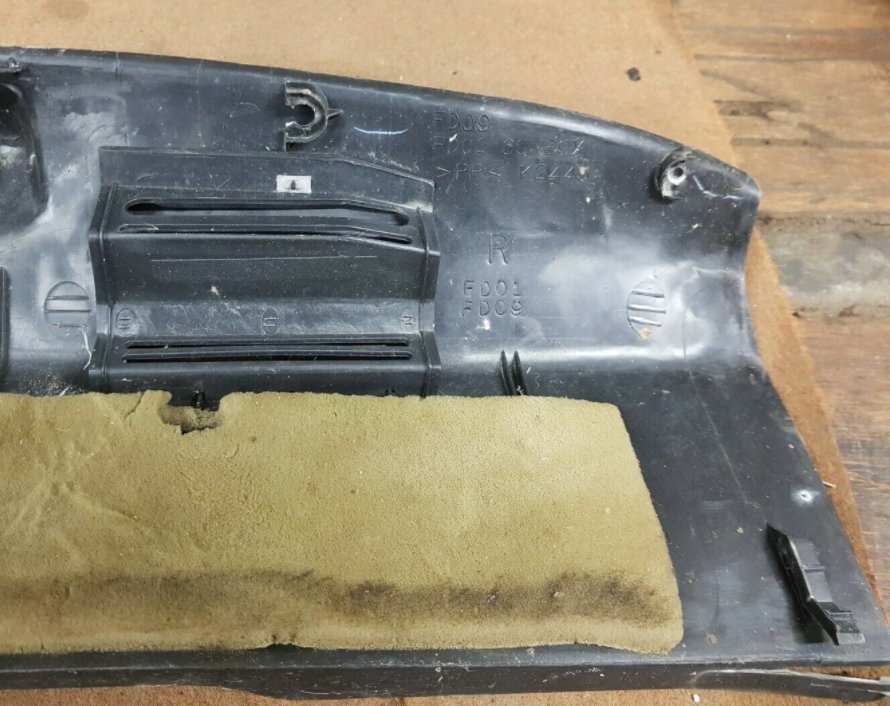
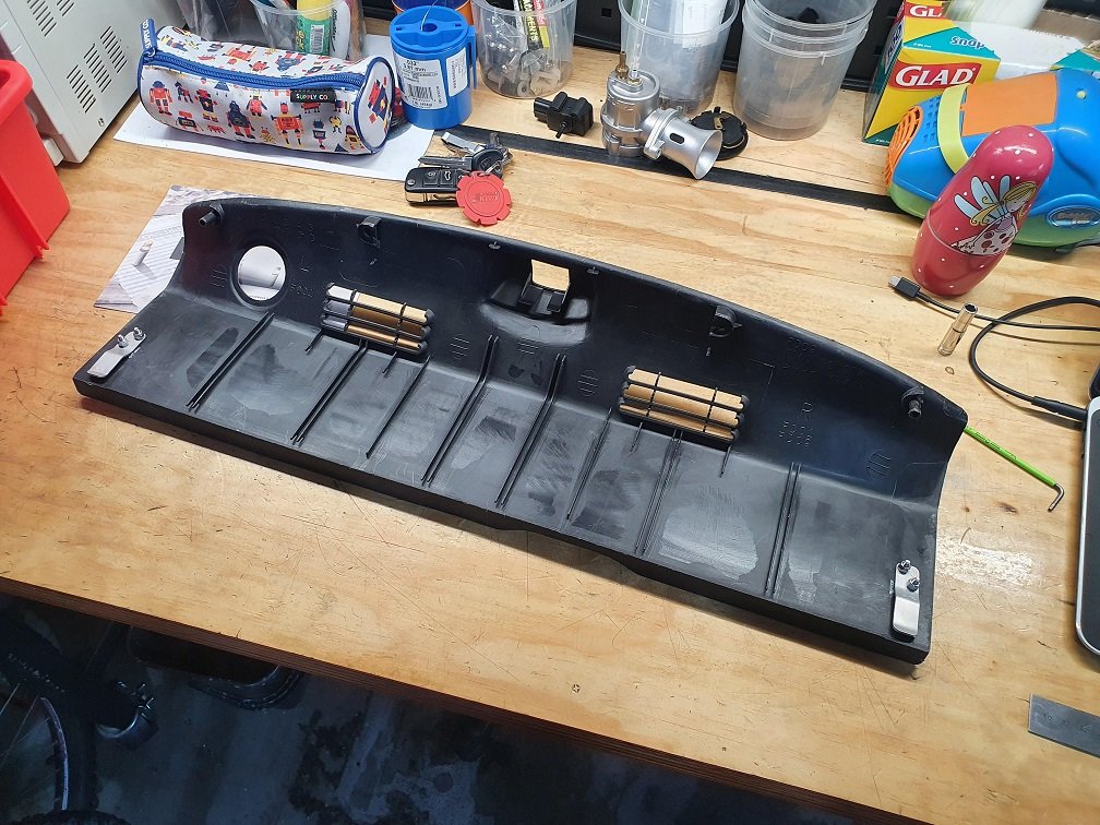
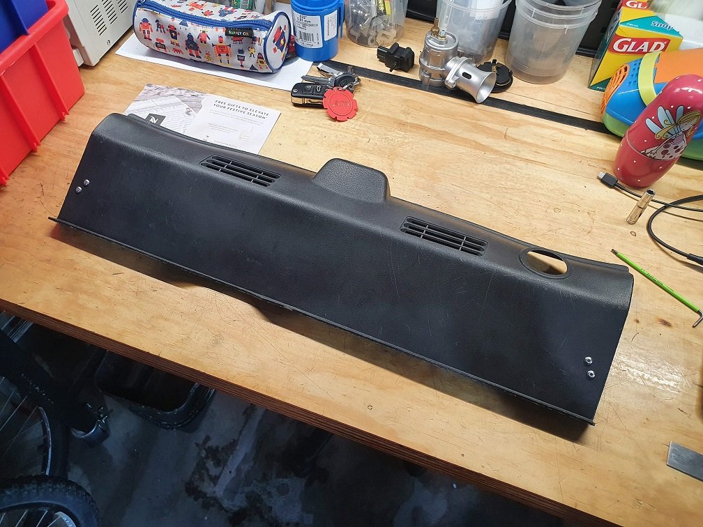
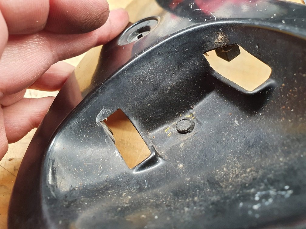
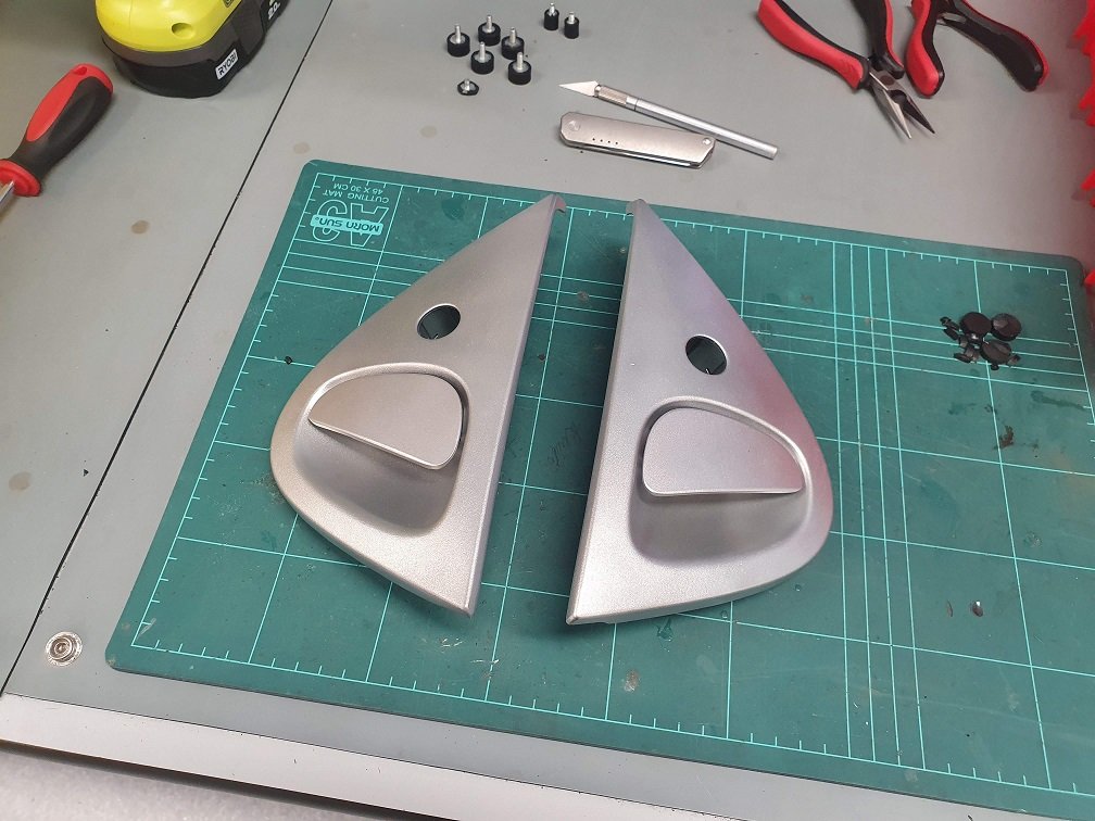
The small win project was the rear boot trim. The piece at the very back of the boot space is broken on most FD's that I've seen. They've meant to have these clip pieces to help keep them from flapping about:
(Image stolen from the nets).
Both of those were snapped off on mine, and the one two I have also...
I suspect you can see where I'm going with this.
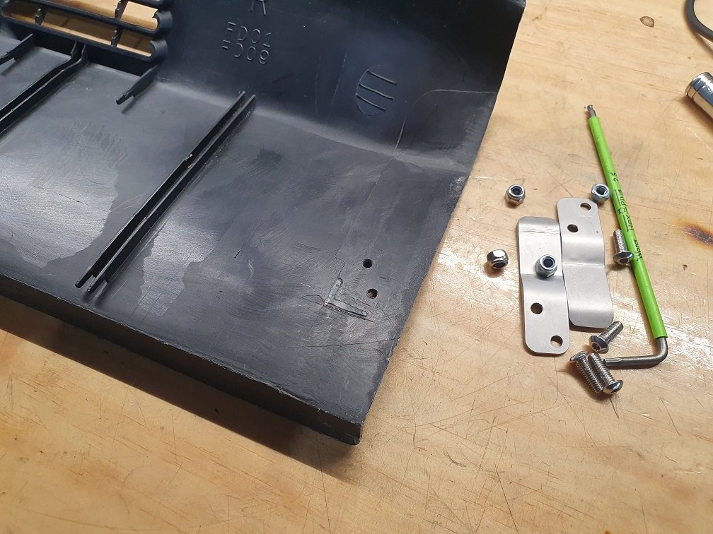
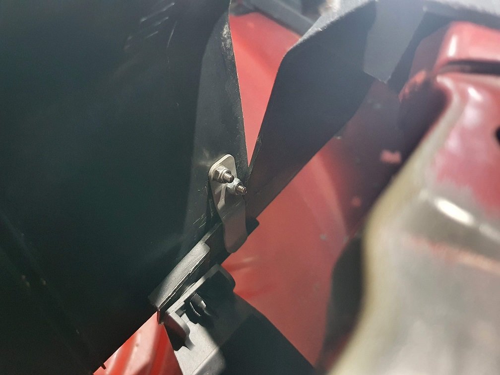
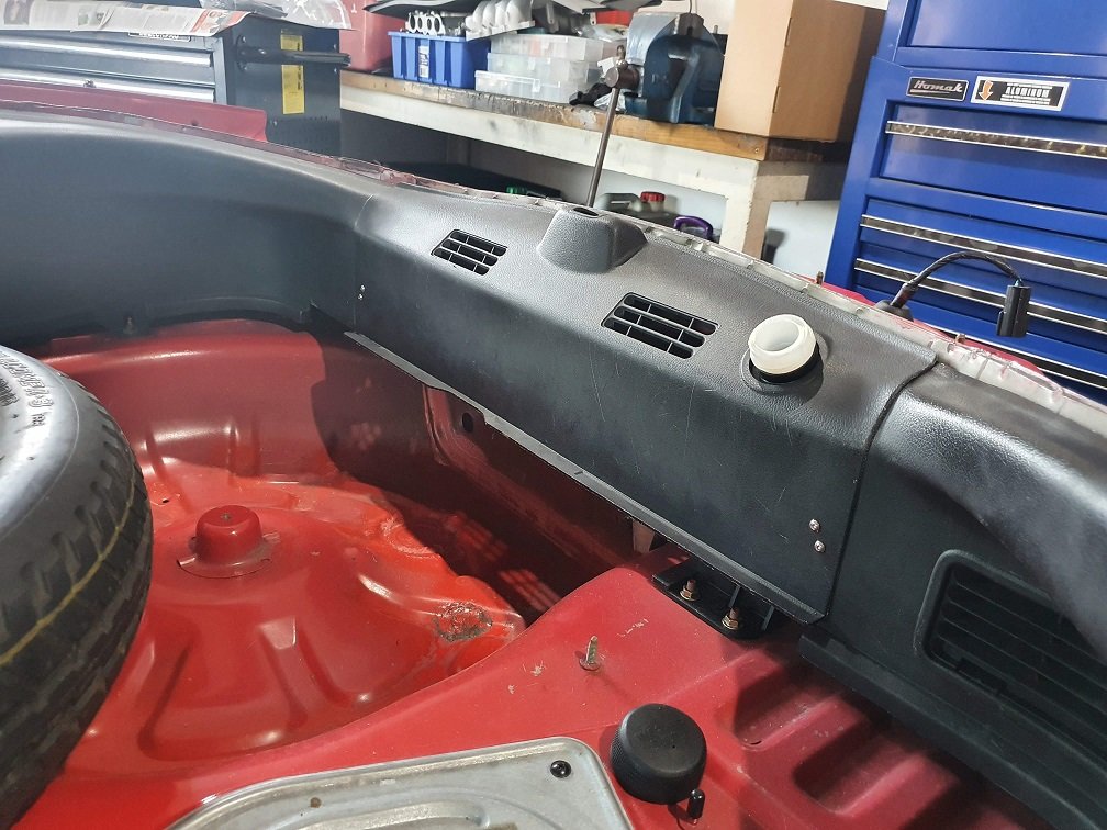
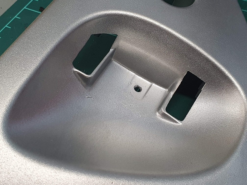
Obviously the fasteners stick out like dogs bollocks at the moment, but I've got something in the works for refinishing all those boot plastics back to as near as OEM as they could get, and I'll powdercoat the heads of those fasteners, and the clips themselves when its all apart again.
It's..... terrifying when something works first time, but, well, hmmmm, here we are? I could cut them again, and do a better job of bending them in the brake, as opposed to bashing them in the vice with a hammer..... But really, they're fine as is.
Back to regularly scheduled programming, which is of course restoring things that aren't really necessary right now... But its about the journey right? Or some **** like that... What it is, is delightfully fun :-). If you're not interested in a stupid level of detail about FD3S door handles... uhhhh, you might want to look away.
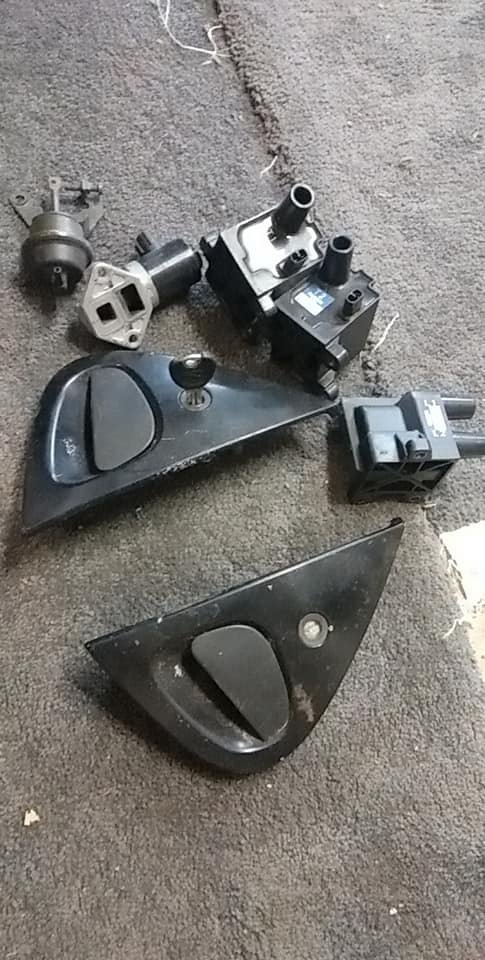
A pair of doorhandles appeared on FB marketplace pretty cheap, because they were really really rough... But they were complete :-). One of mine is missing the plastic trim insert that goes between the lock barrel and the main handle casting, which while not impeding the function, looks hella rough. It's on the drivers side too, so not even like I can ignore it as that's my side of the car! Although I'm not sure for how long, as my four year old (going on fourteen) has informed me that she wants to do a burnout in her red car... Not sure where she is learning these things, but it certainly bought a tear to the eye ;-).
The door handles on these are notorious for snapping, as while the main body is cast aluminium, the handle itself is plastic, and after years of stressing and temp cycles... one day, snaparoo. Both of the ones on the car are okay, but the rough set I purchased was snapped on the drivers side.
Did I mention they were cheap? Hah. Came with a key though, which is nice. I'll obviously swap my lock barrels into them as having different keys for the doors and ignition is a no-go. Those lock barrels will also undoubtedly get a tickly up, as a nice crisp 'snick, snick, snick' as you insert the key is one of life's pleasures... If you're a weirdo... Which I am.
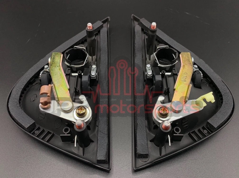
Now, FD3S handles have a known problem that develops over time. As you lift the handle up, they act on a sprung pivot arm which pushes down on the control rod that actuates the door latch. Over time, things wear, and the pivot arm returns further and further, until in its returned position puts the lever point almost in line with the pivot point... This makes the first bit of movement of the handle very, very stiff, and largely contributes to the broken plastic handles, as you really need to wrench on them to open the doors.
You can see here a (completely stolen) picture of a new set of handles:
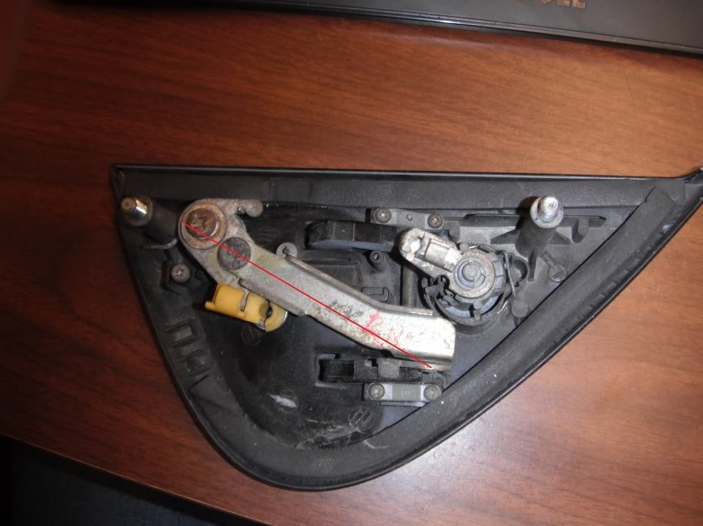
vs a totally worn out set (pic also stolen):
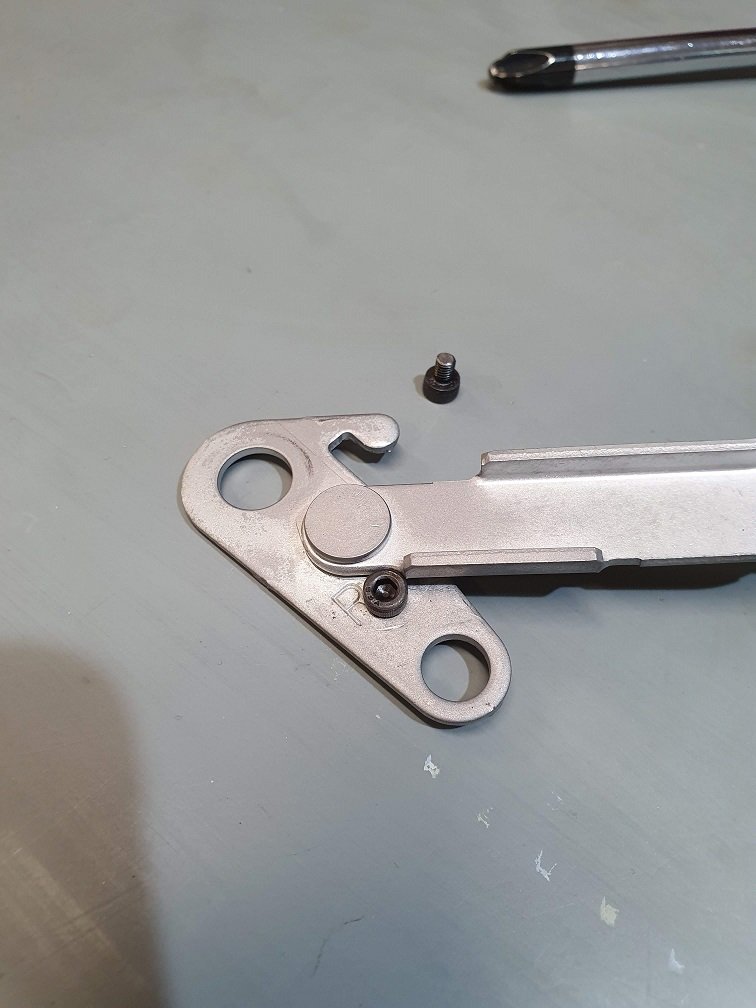
There is a documented mod to fix this, which on the surface seems to makes sense, and that is to carefully drill and tap the lever arm and install a small fastener that stops it returning too far. I went ahead and did this, and it 'sort of' fixes the problem, but its more of a band-aid, and doesn't really address the root cause.
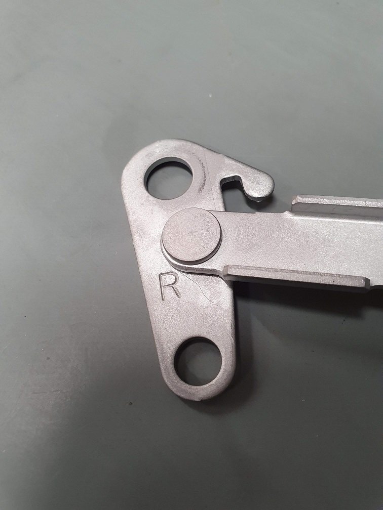
With the handles assembled, and everything held in place like it should be, I scribed a line on the pivot arm in the 'most returned' position it should sit in. Then I offset from this the radius of the head of an m4 cap screw, punched, drilled and tapped:
Voila, problem solved, right!? Yes, but also no. As the pivot return spring now returns the pivot onto this installed stop, it no longer returns the handle onto its intended stop, which is this small push in rubber grommet that sits underneath the handle itself.
So what the newly installed stop ends up doing is ensuring that the pivot doesn't over-return, but that the handle is no longer pulled down tight onto this stop. This means the handle, and attached pivot have an amount of free-play, so they rattle terribly. Can't have that. I think the over all root cause of the initial problem is this small rubber stop wearing out. This is compounded by a small amount of wear in the pivot arm linkages also. Both of these problems we can fix however :-). The following fixed should work with the original plastic handles too, but because one of mine was already broken, I bought a pair of the replacement cast aluminium ones. They look basically identical though.
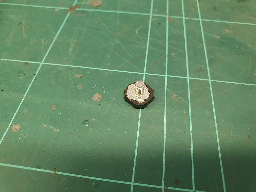
I drilled and tapped (M4) the small hole the push in rubber stopped goes into, and then modified some M4 rubber equipment feet, shortening them down to ~2.3mm. I figured this would give an amount of adjustability if needed, but TBH, I just put them in as tight as they would go, secured them with a nut on the back side, and they were spot on from the get-go. I've also sand, and then vapor blasted the handle bodies in these pics, that's why they look so shiny :-).
Stupid me didn't take a photo of what it looks like installed from the front, but I'm sure you can imagine. I'll have one later when they're all assembled.
The other part of this problem is that wear in the pivot arm itself. I think this is actually a pretty small contributor to the over all problem, but tuning it up a little can't hurt. I grabbed a couple of M4 washers, which were pretty terribly manufactured, resulting in different thicknesses from 0.7mm to 1.1mm... This was great though, as it meant I had options, as I was going to use one as a shim :-). Ended up on around 0.8mm being about right.
You can see it installed between the rod-clamp, with 'B' on it, and the handle itself. Depending on which side you put a shim here, it will move the handle relative to the housing, so make sure you put it on the side that results in it looking right :-). Probably different for every combination. I suspect thinner plastic shims, installed on each side would be a better option. This limits the side to side play in the pivot, and just generally tunes everything up so its a bit nicer.
With all that sorted, I fully assembled them with everything in place and damn, satisfying result! Lovely smooth action, no stiff point at the beginning of the travel, no rattle, nice and sorted. I left the over-return stop in place, the spring was returning the handles onto the new rubber stoppers, and it was only *just* touching the cap-head stop. This means that if those rubber stoppers don't live up to the task (a total possibility), the pivot will still work, but things will just start to rattle again, letting me know I need to find a better rubber stopper solution down the line... Cross that bridge if I come to it?
With the mechanicals sorted, next up is the cosmetic restoration, which has turned in a slight cluster-****. Choose your powdercoaters wisely my friends!
Been away for a while (new dad life) but this is inspiring. One of the things I dislike on my FD is the door handle action. It feels .... uneven and fragile. Would love a nice build of pressure with a *snick at the end. Also should pay attention to my lock tumbler, although I have an aftermarket remote door lock fob which limits my key time...
Bravo. If you ever convert your car to LHD and wanna sell... . Still got to go through your later posts.
Exceptional work and inspirational. I'm going to be sniping future small projects from this thread for years to come. Surprisingly wiper motor and door handles are at the top there.
Loving all of it except for the headlights.... somehow the curve of them and the way the housing sits in the pop-ups doesn't feel right. Maybe the poly material adds to that? But I do agree the stock headlights are made for games of chicken.
Wanted to share the spacing used on my car for a reference point for you. 20mm up front (stock studs replaced with ARPs) and 25mm rear (bolt on adaptors that use stock studs). The car sits on TEIN Flex Zs. In this picture the rear is as it comes set by TEIN (I'd say about a 1.5" drop from stock) while the front is about a 1.3" drop. I have since replaced the coilovers with a fresh set of TEINs and the front has been dropped 1.5" as well, but no pics since then. Not to hi-jack the thread but just to give you something to go off of when you get there. Silver car on the left.
I don't have too many pics of the car at angles to show the spacers perfectly, but one more.
If at a later point you're interested in specific angle pics to see fitment just let me know (post winter here in the Northern hemisphere of course).
Exceptional work and inspirational. I'm going to be sniping future small projects from this thread for years to come. Surprisingly wiper motor and door handles are at the top there.
Loving all of it except for the headlights.... somehow the curve of them and the way the housing sits in the pop-ups doesn't feel right. Maybe the poly material adds to that? But I do agree the stock headlights are made for games of chicken.
Wanted to share the spacing used on my car for a reference point for you. 20mm up front (stock studs replaced with ARPs) and 25mm rear (bolt on adaptors that use stock studs). The car sits on TEIN Flex Zs. In this picture the rear is as it comes set by TEIN (I'd say about a 1.5" drop from stock) while the front is about a 1.3" drop. I have since replaced the coilovers with a fresh set of TEINs and the front has been dropped 1.5" as well, but no pics since then. Not to hi-jack the thread but just to give you something to go off of when you get there. Silver car on the left.
If at a later point you're interested in specific angle pics to see fitment just let me know (post winter here in the Northern hemisphere of course).
I agree on the headlights, I'm not 100% sold on them... But I've convinced myself that because they're down most of the time, unless its dark, they wont bother me too much. As long as they perform decently. They're a 100% replaceable swap though, probably 15 mins to put the originals back in and get them aimed. Some of the new-fangled LED replacement bulbs are apparently excellent, give a correct beam pattern in non-projector housings, and output a heap more light, so might be something to investigate down the line. Every other exterior bulb is LED now, and I've got some of the 93 - 98 fog lights which don't have the yellow lense in them to clean things up a little. I'll keep these ones as well of course, as I think they only came on the 92s.
Thanks heaps for those pics, they really do help! I plan on buying 30mm bolt on spacers (the widest we can legally run here in NZ), and machining them down in thickness to get things sitting just right. I'll get the thing running and driving on the stock suspension for the moment though. 180,000 k's on the car though, so if they haven't been replaced, it'll likely be a pretty loose ride :-/.
Been away for a while (new dad life) but this is inspiring. One of the things I dislike on my FD is the door handle action. It feels .... uneven and fragile. Would love a nice build of pressure with a *snick at the end. Also should pay attention to my lock tumbler, although I have an aftermarket remote door lock fob which limits my key time...
Bravo. If you ever convert your car to LHD and wanna sell... . Still got to go through your later posts.
Cheers! Can relate to new-dad life taking up a lot of time. My sprog is just about to turn 5, takes up a lot of time, but love every minute :-).
All the things you touch in the car have to be 'right' eh? Like, my daily is a pretty beat up late 2000's audi diesel, and for the most part, its not a terrible car... But the drivers door handle is just a little loose, and because its almost the first thing you interact with every time you get in the car, it makes the whole thing feel.... downtrodden? Yeah. Should really fix it... but working on the daily is something I avoid like the plague!
Thanks! It's such a blessing... you don't know until you go through it is very true. Never again would I turn my nose up on folk who baby photo bomb, lol.
A recent fun car prior to this was a 997 911 Carrera C2S. There is something to having that solid door close, quality handle action, windows that roll up and down with authority and a firm seal, the leather trimmed dash, windshield wipers that would break a walnut, AC that'll freeze your drink.... the Germans do some things really well. The FD is such an intuitive driver, stunningly well sculpted, and doesn't get the sometimes negative reactions driving a 911 can (ie everyone loves the FD or just don't notice it) so I want to keep it. But those cheap touches are what hurts it for me. I usually dislike custom interior work but in the future I would like to see if a quality craftsman can do a good leather dash and plastics wrap. For now with limited time I have to tackle the bigger things and build up my own mechanical and restoration abilities to get cleaner results on the finer details without breaking plastics along the way.
Thanks for sharing all this with us. Looking forward to what the final spacing works out the best for you.
I spent a considerable amount of time chasing down and remedying squeaks and rattles in the interior and the result was quite splendid.
But I recently installed the RZ/Spirit R "Pado, Nii - Doa". Now when my knee presses against it the door, the trim creaks annoyingly.
I discovered that I should also have installed a brace (see below). I can't find the brace in any parts catalogues. It may have come with the pad, but the diagram in the parts catalogue only shows the pad.
So I may have to fabricate the brace myself.
(Pad part number: F104-68-4Z0).
Picture from FSM update for first RZ.
******
It seems the entire door card assembly for the RZ had its own part number (F104-68-420A - 2 person) and that the part was updated twice in the first year's production.
I wonder if that brace and knee pad would help with the door trim rattles / squeaks in general. I've got a couple of ideas about beefing them up a little, as they're frightfully light on attachment from the factory. Lightweight sports car for sure, but I'd like to feel like I'm not yanking off the door trim every time I close the doors :-/.
I've used a lot of fabric 'tesa' tape on the edges of all the plastic pull / trim pieces that screw into the door cards, dash cluster, console, etc, so hopefully I can get it reasonably quiet. All the interior is from a much lower k's car, so maybe things will be a bit tighter? Wishful thinking maybe, hah ;-).
I wet blasted (vapor blasted) them at work. We've got a Vixen 1215, and its just an amazing machine. I use it for cleaning heaps of stuff. Works amazingly well on plastics if you crank the pressure down. Honestly, I don't think there is another way of cleaning cast aluminium to get this result, its just bloody fantastic. Sort of peens over the surface too, so its less likely to develop fluffy corrosion or trap dirt in the future. Probably 20 mins work in each of those manifolds, but its time you're standing there, listening to an audio book under your earmuffs, watching your manifold go from an overspray coated piece of trash to something beautiful... So it's not like its a chore ;-). My boss tells me its 'wellbeing time' (he's a car-nut too :-) ).
Motor keg will stay together for the moment, but everything hanging off if will be dealt to. Then when the motor pops (I have absolutely no idea of its history, except that I've seen it run, it doesn't smoke, and has decent compression...) I can yank it and rebuild it too.
However, my wife has just informed me that sinking two whisky and sodas and working on intricate car parts might not be the best of plans, so I might retire from the garage for the evening, hah ;-).
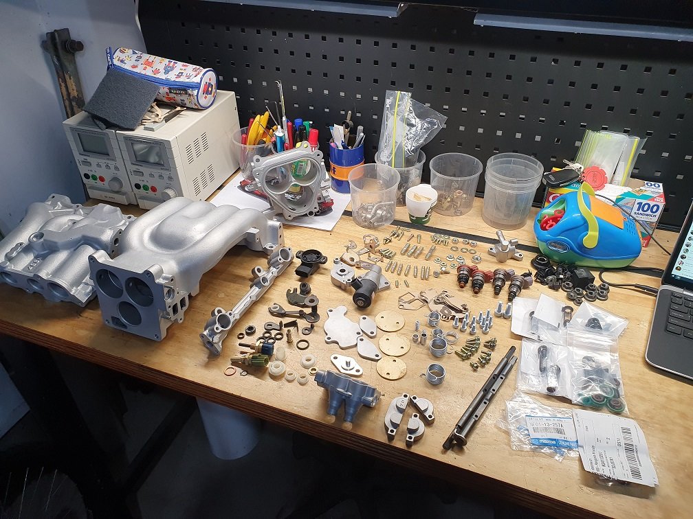
Whoa, the throttle bodies on these things are a..... thing. I got the above jigsaw all back together. Turns out I'd lost one of the plastic spring bushes, and the flange on the other was cracking off, so I grabbed an off cut of acetal from work and turned up a couple of new ones. That let me get the thing reassembled. I took a heap of photos of how everything came apart, so getting it back together wasn't too much of an issue. Kinda fiddly in spots, but follow your nose and it goes back together reasonably easily. The throttle shaft seals still seemed pliable and plump, so I didn't replace them... Time will tell if that comes around to bite me in the ***. Ideally I'd like to go with some sort of e-throttle setup in the future.
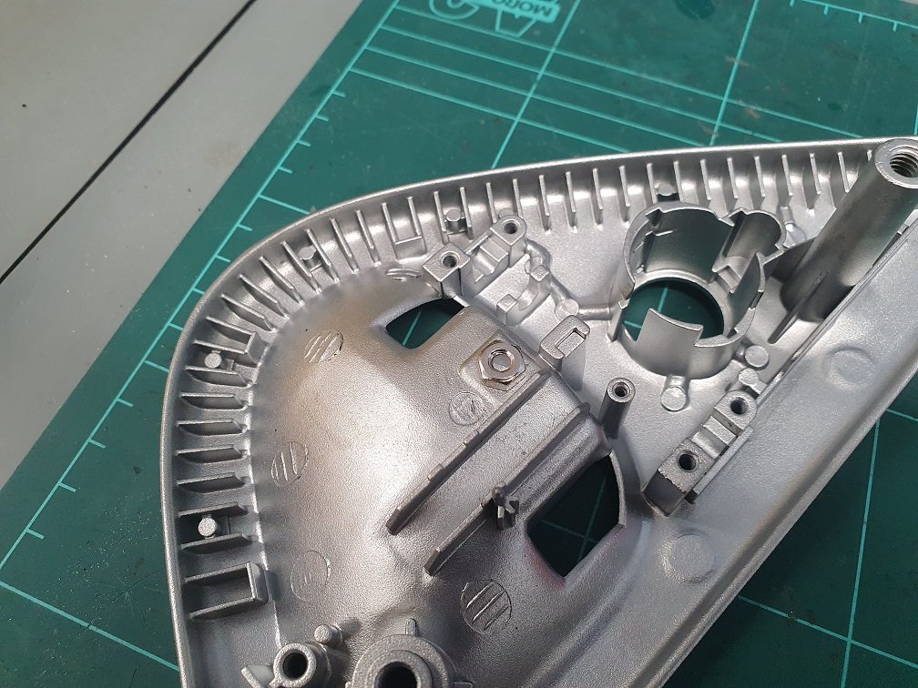
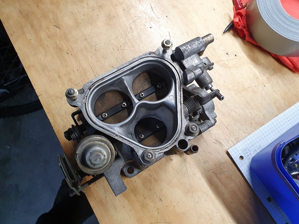
There wasn't actually a complete throttle body with the car when I got it, so I purchased this one secondhand, and it was pretty filthy:
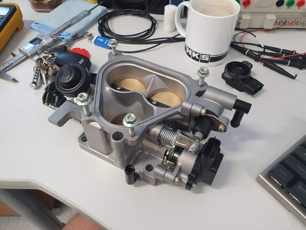
But, it was complete, and moved smoothly :-). After stripping, blasting everything (lots of careful masking involved), kind of a pain in the ***....
Much better.
But holy crap, there are a lot of adjustments on these things! There are threads all over the internets of people having problems setting these up, so I thought I'd better develop a plan to follow. Not saying the plan is a 100% way to go, but I need something to follow so I can go through a process and collect data, and iterate from there. Going to write this plan out here so I can refer back to it later when I've forgotten all this again.
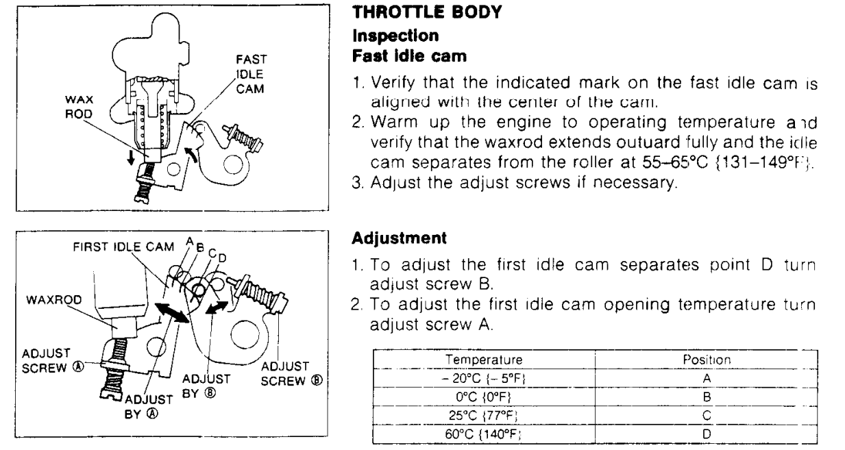
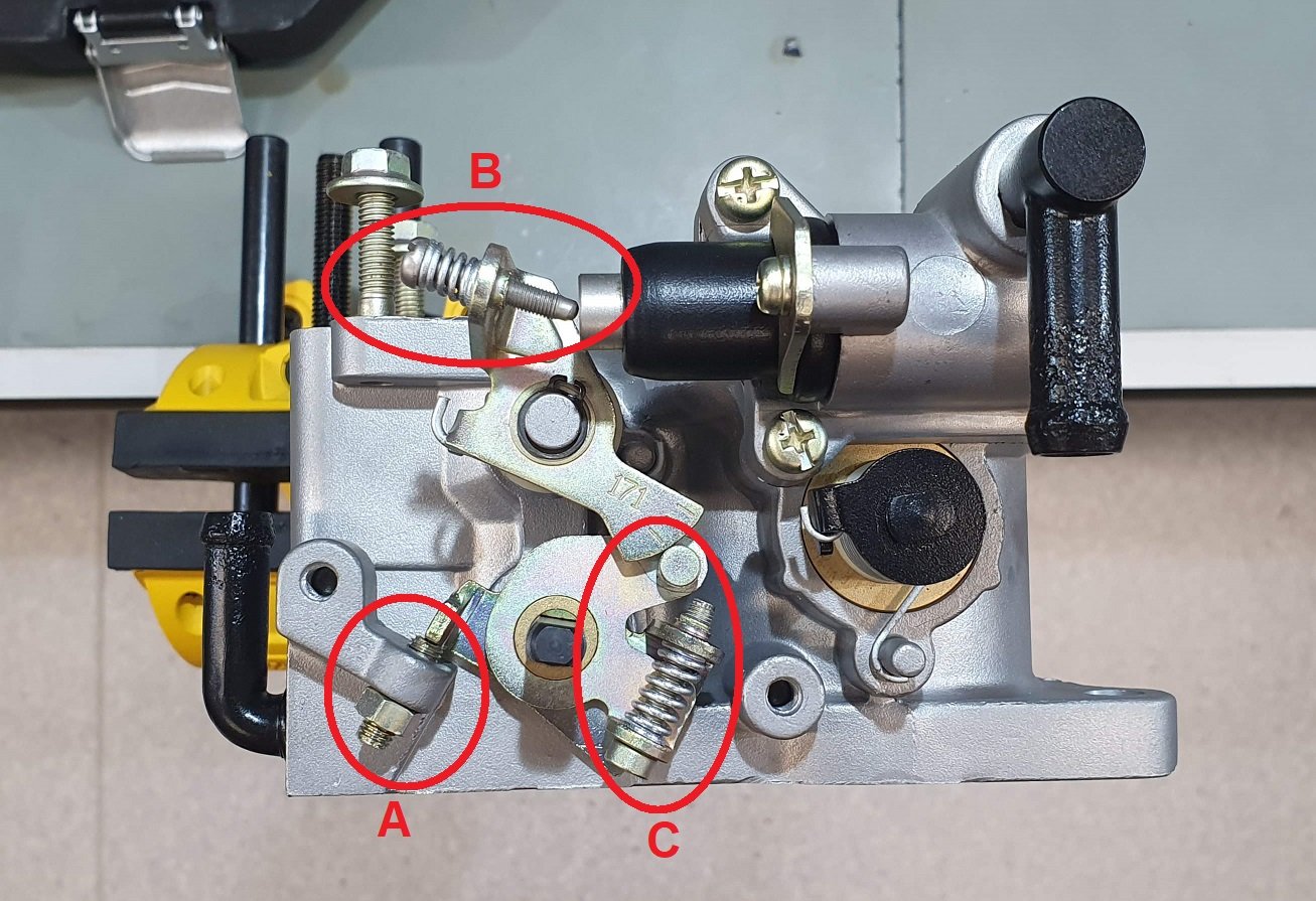
The first screw I've set is screw A. This is the stop that the single butterfly stops against. This single butterfly feeds the primary intake ports. As it's in the name, these port are the primary ones, so they're used all the time, along with the primary injectors always delivering fuel. My initial setting for this is that the primary butterfly stops against this when it is fully closed. After aligning the throttle blade, and thread locking the screws in place, I let the throttle close as far as it can against the housing. I then advanced this screw till it was just in contact, then about 1/10th of a turn more. This should mean the throttle blade is never eating the throttle body housing, but closes as much as possible.
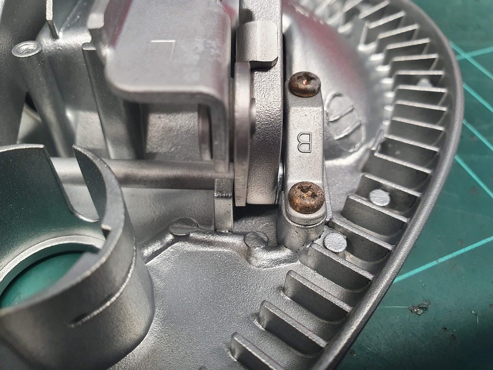
Screws B and C adjust the cold start warmup system. You can see the two black pipes in this picture. Coolant flows through these, which warms up and extends the wax pellet push-rod screw B is pushing against. Unfortunately they're a little corroded on the outside, but there is still heaps of metal there. Will always run anticorrosive coolant in this, so should progress any further. This wax pellet rod extends as the coolant gets hotter, and retracts as when things cool down. This screw is threaded into a cammed bracket, which has three marks on the cam (one of them is obscured by the red oval I've drawn, but its there). The FSM has specs for the relative positions of the roller on the bracket screw C threads into (we'll get to this one in a minute) and the cam at different temperatures. The upper most (in my picture) mark should be central on the roller at -20degC, the next one down at 0degC, the next one down at 25degC, and finally off the lower edge of the cam at 60 degC. It's pretty hot in my office today, so I've adjusted screw B such that the roller is lined up with the third mark.
Screw C adjusts how much effect this cam actually has on the throttle blade position. As you screw this in more and more, it opens the throttle blade more and more, as long as the roller is contacting the cam. I suspect the final setting for this will be such that the roller separates from the cam just as it is passing over the lower edge, with without a sudden jump in its movement. Currently, I've set it so the roller is only *just* touching the cam at this 25degC position, for reasons that will hopefully become clear :-).
Cold start systems are important, but they're only ever going to work properly if the base idle speed with the engine at normal operating temp is setup correctly. The throttle obviously has adjustments for this as well.
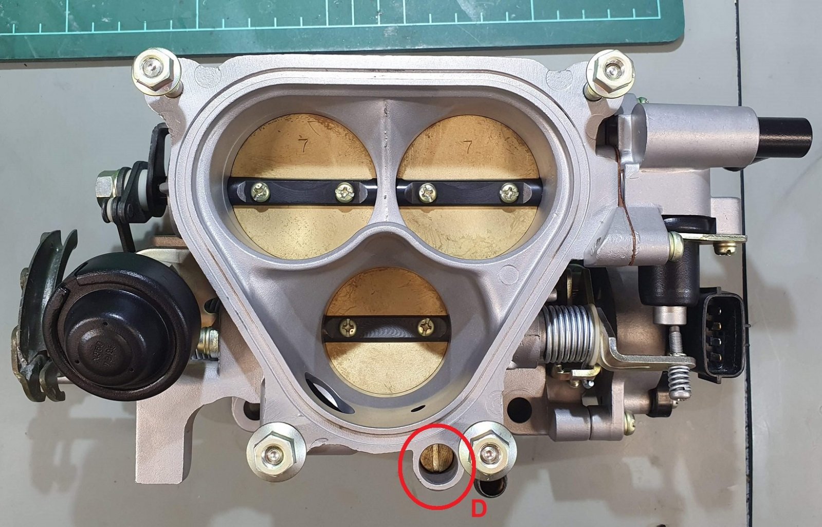
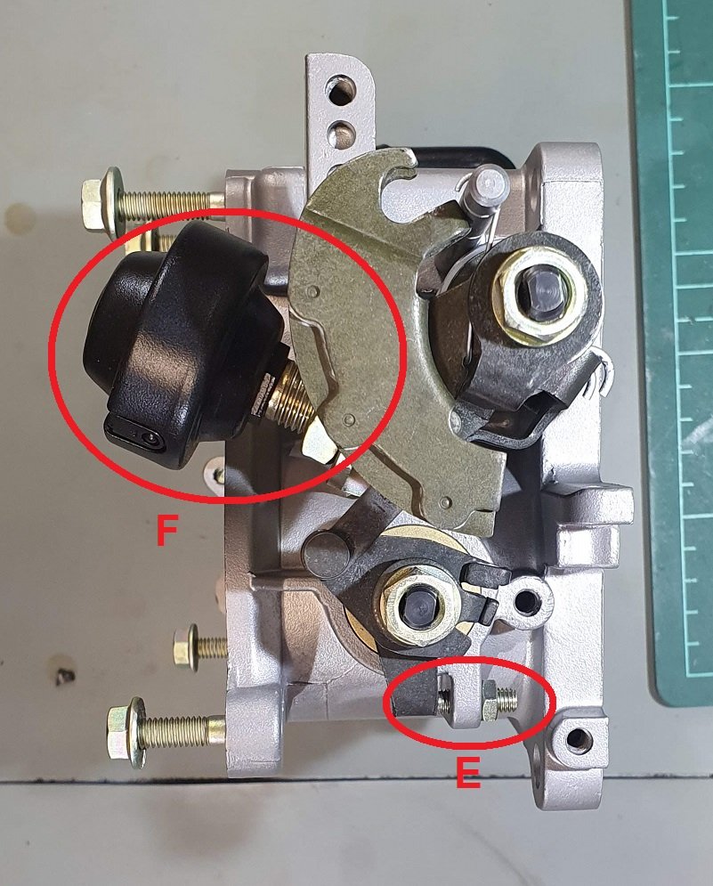
Screw D is called the Air Adjust Screw (AAS), and screw E is called the Throttle Adjust Screw (TAS). Screw D has a tapered end on it and fits into a matched tapered orifice. This orifice is connected across either side of the primary throttle blade, so as you back the screw out, it allows more and more air to bypass the throttle blade. Screw E is the stop for the the secondary throttle blades, and sets their closed position. In practice, these screws have the same effect on the idle, in that they will let more air into the engine. There is a slight difference though, as at idle the ECU wont be using the secondary injectors, so adjusting the idle with screw E will let more air into the engine via the secondary ports, but this wont have any fuel injected with it. This wont be an issue though, as at idle things are happening very slowly, and there is heaps of time for the charge to mix in the combustion chamber as it whizzes around to the other side of the motor to make brap brap noises. Reading the FSM, what I can parse out is that you use screw E to broadly set the normal operating temp idle speed, and then screw D to fine tune it.
I've set screw E in the same way I set screw A, such that the secondary throttle blades fully close to within a bee's dick of the throttle body housing. I've wound screw D all the way in, so there should be no air bypassing the primary throttle.
The last adjustment is the damper dashpot, F. This is a damper the throttle closes against. It's hard to push in, but extends with no effort. Lots of bump damping, no rebound damping. This needs to be set with the motor at normal operating temp, and such that the throttle breaks contact with the plunger at an engine speed of 2600 - 3000 rpm. Obviously this will need the engine running properly at N.O.T. To setup, so I've wound it out so it doesn't contact the throttle at all.
Reading through that, there might seem like some odd decisions, as I've essentially set the throttle up in such a way to ensure the thing isn't going to idle. It's going to have almost no air bypassing the throttle, will starve and die. This is for a reason however, and comes back to how I like to tune a setup. First thing is to get the engine firing and running, probably with some throttle manually applied. Then I can get it up to temperature, check for leaks, fires, all those things. With the engine up to temp I can use screws D and E to set the normal operating temp idle. It's really important this is done without the cold start system having any effect whatsoever, as if it is, when you go to set the cold start up, your normal idle setting will also be effected, and you'll end up chasing your tail.
Now, the FD also has an ECU control idle air solenoid which can allow varying amounts of air to bypass the throttle, but for all this initial mechanical setup, I'll keep this unplugged to eliminate it. AFAIK the ECU only uses it to idle up the motor when the A/C, power steering, or alternator are loading things up.
There is also the TPS to think about. The FD TPS is a little odd in that it has two analogue output channels, narrow range and full range. Talking to Ray (arghx), it sounds like this is a throwback to the FC3S days, and probably something to do with Mazda re-using existing code in the FD ECUs. Total speculation, but having been an engineer on a few evolving projects, this is totally something that would happen. The FSM has specs on setting this up. With the throttle closed, adjust it so the narrow-range signal is between 0.75V and 1.25V, and the full range signal is between 0.1V - 0.7V. I powered up the TPS from my bench supply and set it thusly.
Strats:
Stock ECU initially, to get things running, proof the rest of the system, and ensure it doesn't burst into flames. It's a 'known quantity' as such.
Make the thing run, will need the throttle manually opened to keep running.
Get it up to normal operating temp
Make sure everything is functioning like it should. No error codes from the ECU, so no limp modes or anything (exception to this is the idle control solenoid, but I can trick the ECU into thinking this is fine with a resistor in its place).
Adjust the warm idle speed to just below target (~750RPM) with screw E
Adjust the warm idle speed to the final target with screw D.
Adjust dashpot F so the the throttle breaks away from the plunger at an engine speed of 2600RPM.
Turn the thing off, go inside and have many whiskies.
Recover from hangover. Remember: You're old now, this might take a couple of days.
With the thing dead stone cold, try to start it with no throttle applied. Expectation is that it will not start.
Advance screw C 1 turn, try again. Repeat this procedure till the engine starts with no manual throttle opening. Idle speed should be higher than warm idle target.
Allow the engine to warm up, idle should reduce gradually as it does and the wax pellet rod extends.
Iterate from here. The only screw that should need adjusting at this point is screw C.
Hopefully I can pull that off.
In other news, most of the supplies needed to build the EM (main engine) harness have shown up! Huzzah! I'm going full ham-spec on this. The car doesn't need it at all... But I've built lots of high-tier harnesses before for other people, and I really want something totally schmick for my own car for once. M22759/32 throughout, twisted, DR25 sheathed, booted, sealed.. All the good things. As much as can be with using OEM automotive connectors also. I've designed it with lots of extras in mind down the road, as I don't want to have to build another one for this car, ever. When I want to change out the ECU for something other than the stock one or a power FC I can just make adaptor harnesses at the ECU end, nice and easy. Just got through the design process for the layering, built a test section for the main core to make sure it was going to lay up nice, looks lovely :-).
Yeah, we run a pretty active Formula Student team which is excellent, and I really enjoy helping out students with any of their automotive pursuits :-).
Sounds like I'll need to track you down. Just started as a first year engineering student at UC and purchased a series 7 just 2 weeks ago
This car is going to be incredibly clean when its done
Cheers, that's the idea... Now, WHEN it's 'done' will be the trick, hah! Still, journey, not destination and all that, having heaps of fun with it, so that's the key bit.
It's been a hot minute since I've done anything on this. Work has been pretty mental with preparing material for remote delivery due to..... reasons, and I've really not had a lot of garage time!
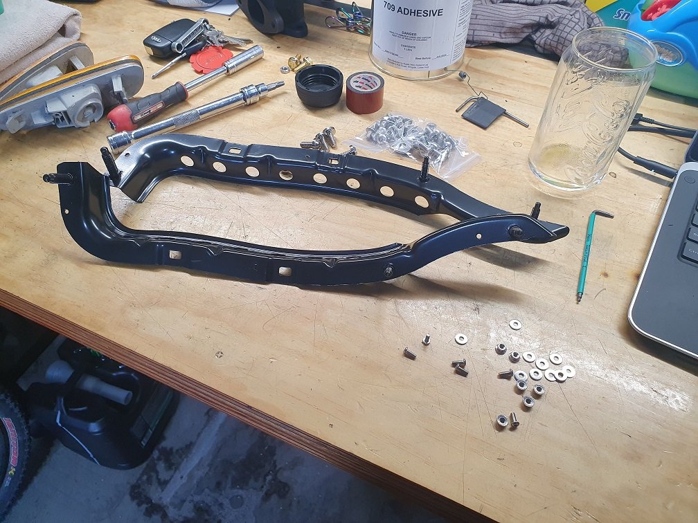
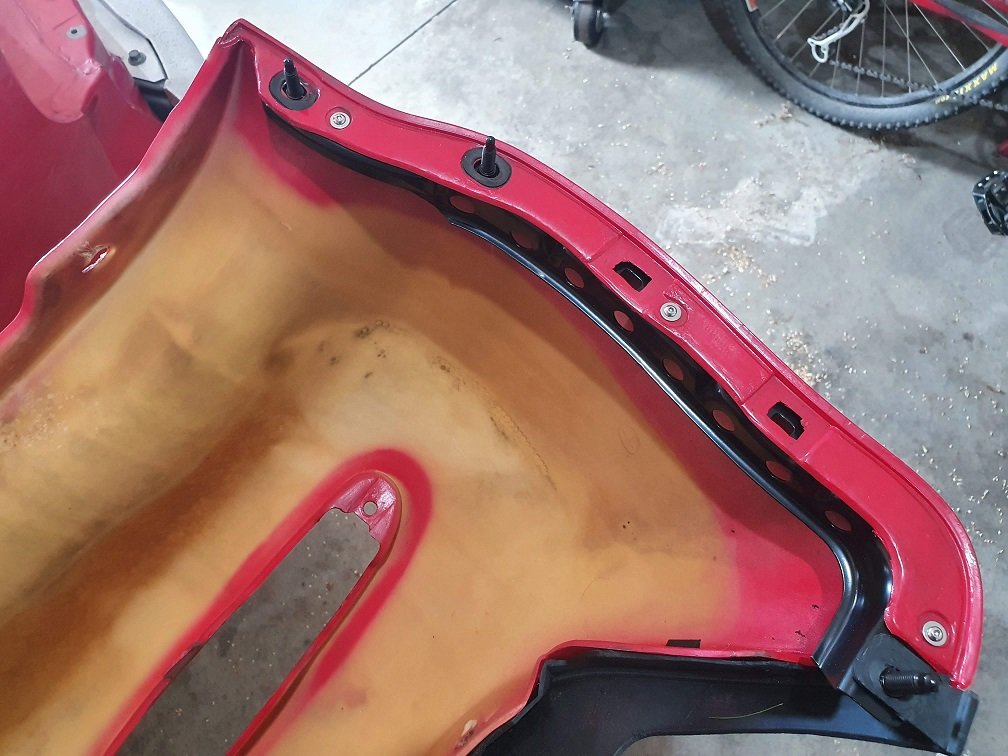
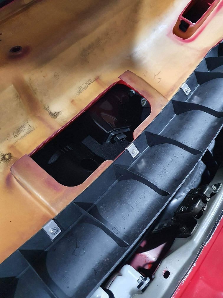
Needed an easy win, and I have to get the rear bumper back on so I can reassemble the rest of the interior, figured it was a good box to tick off. In their infinite wisdom, Mazda have designed things such that you have to remove pretty much every piece of interior trim behind the FRONT seats to get the rear bumper off... So clearly the bumper needs to be back in place before it can go back together. I'll caveat all the following work by saying that it'll be coming apart again in a couple of years when the car gets painted, but I wanted to make sure that would be as easy as possible. Part of this is making it so I hopefully don't have to deal with rust fasteners again... ever. Pretty much every fastener on the rear bumper was a rusted mess. Weirdly, the body of the car itself is fine, but the metal brackets on the inside of the bumper were in many, many pieces... Many of the bolts below the tail lights holding the skin on there required hammer and chisel action to remove, and the speed-nuts / screws holding the rear valence on were pretty much unrecognisable as having ever been fasteners in the first place... It was just all a bit of a mess.
I bought new bumper brackets from Mazda. These ******* were NOT cheap, around $230 per side! But, the bumper skin itself is really really tidy, and people seem to want moonbeams for a good rear bumper, so I just went with it. They are originally riveted in place, and I was careful drilling those out to remove all the old rested pieces. I've secured the new ones with M3 stainless screws and nylocs. I've also omitted the clips for the moment, as they were a complete ball-ache to get popped loose when I removed the bumper so long ago... When It gets painted in a couple of years I'll re-fit them.
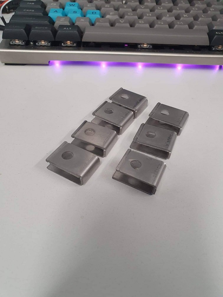
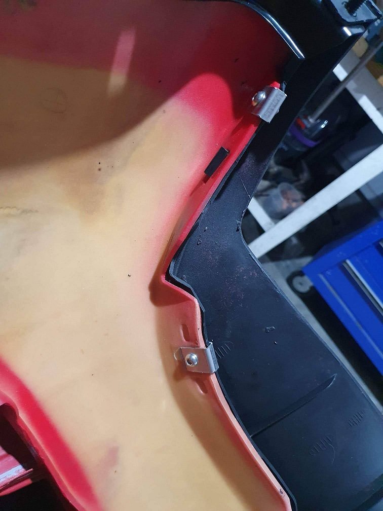
The lower valence is not to shabby on this car, a little warped in one place, but I'll be able to make another couple of clips to hold it in place. Some time in CAD, and then the waterjet, and then the finger folder and I had some replacement speed-nuts (with separate nuts, so thus nullifying the 'speed' part, hah). All stainless to hopefully never give a problem in the future
And some new fasteners for the top of the skin. I would have liked to find torx head ones for this, as they were originally, but these were easily available and I've convinced myself they're fine.
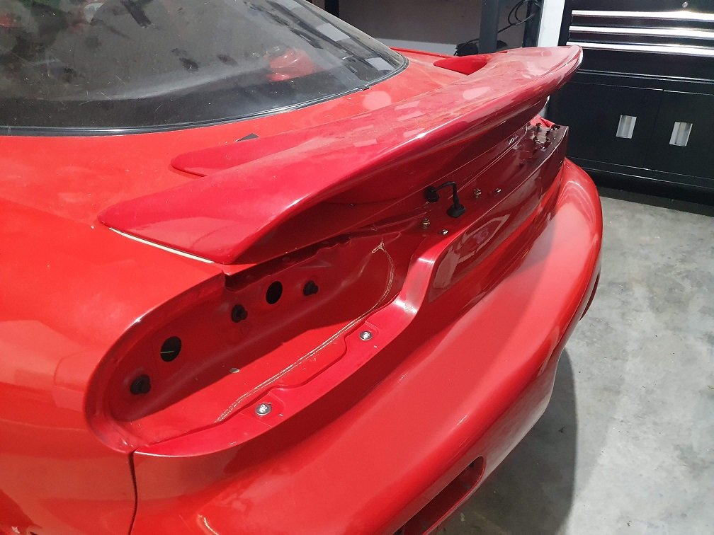
Yeap, that spoiler is a completely different red... It it, however, not cracked, and in one piece, which is much better than the one which WAS on there when I got the car. Future problem, hah.
I also considered buying a new rear bumper bracket, one of the brackets on my bumper was detaching itself and was getting sloppy.
I decided to instead try to repair it by running a threading die over the threads to clean and resurface them, and then reinforced the bracket back to the bumper using a couple new oversized rivets.
It ended up working out pretty good for me.
But honestly everything about the rear bumper is a PIA, and the smarter you can put it back together now, the less you have to worry about it for the future.
Yeap, that spoiler is a completely different red... It it, however, not cracked, and in one piece, which is much better than the one which WAS on there when I got the car. Future problem, hah.[/QUOTE]
Is that the red series 6 spoiler that was up for sale on FB here a few weeks ago? If it is then you beat me to grabbing it
Is that the red series 6 spoiler that was up for sale on FB here a few weeks ago? If it is then you beat me to grabbing it
No too sure if its the same one, I bought it quite a few months back. Guy had a minty mint mint set of front indicator units he chucked in with it too, so it was a really good score. If I see any come up I'll give you a shout.


 . Still got to go through your later posts.


.jpg.5d94bba64e109d2c88eca846cf298e20.jpg)