Indepth study of WAI injection systems
 02-15-09, 06:00 AM
#1
Senior Member
Thread Starter

Join Date: Sep 2006
Location: uk
Posts: 402
Likes: 0
Received 0 Likes
on
0 Posts
Indepth study of WAI injection systems
It is my attempt of explaining how different type of systems work and its advantage and dis-advantage, based on current systems offered. It is a my view and findings, please do chime in and discuss.
1st January 2008- updated
It is my attempt of explaining how different type of systems work and its advantage and dis-advantage, based on current systems offered. It is a my view and findings, please do chime in and discuss.
1) Single-stage
2) Two-stage
3) Progressive Pump Speed system (PPS)
4) PWM Valve controlled system
5) System that will integrate well with third party controllers.
6) Direct port
-------------------------------------------------------------------------------------------------------------------------------- -
The single stage:
The single stage WAI (water alcohol injection), as the heading implies, is not as basic as most people expects. It some cases, it will out perform a two-dimension progressive system. Please do not underestimate it. I will try to explain briefly why after the next few paragraphs.
Having a single trigger point and a fixed flow rate, one will get to know its effect on your engine very quickly. Due to its consistent repeatability, it is very easy to tune. This type of system is normally set to start spray in the peak torque region, where the engine is most likely to knock.
As the RPM climbs, the ratio of water to mass air tends to decrease. This may not be a bad thing because the tendency to knock is also lessen as the wastegate starts to open and prevent the boost pressure from increasing further. The volumetric efficiency of the engine also decreases as RPM climbs, breathing in less air. This also has the effect of reducing the engine's tendency to knock, demand of WAI flow is less. Unfortunately some engines do require continuous WAI flow at higher RPM due to heat build up through friction and turbo efficiency.
A 2-D pump speed system based on manifold pressure is a little bit tricky to tune compared to the single stage system. The user has to set the start and finish pressure points, those points are sometimes set at a considerable distance apart. Matching those operation points in a 3-D environment such as RPM/Boost ramp (nonlinear) is quite difficult. We will be discussing it in more details later.
FOR:
1) Low cost, simple and dependable.
2) Easy to tune
3) Very effective on a stock factory set up with a few pounds of boost extra.
AGAINST:
1) Dynamic operating range is narrow, may not be as effective on a high RPM knock suppression.
2) For high power/ high % alcohol applications, considerable fuel has to be taken out (boost clamp) to make the afr tolerable. Some sort of failsafe mechanism is necessary to prevent engine destruction when the WAI fails to delivery the correct flow.
At present, adding a second manifold pressure switch to active an additional solenoid valve at a higher manifold pressure is the definition of a 2-stage system.
This arrangement gives the system greater flexibility as well as extending the flow range. It addresses the problem associated with the single stage system, too much flow at the start and not enough when RPM climbs beyond the wastegate setting.
As the system is based on boost trigger, it still won?t address the RPM related flow. For a turbo charge engine, the most significant active regions are the boost ramping stage and engine?s maximum torque range. A two-stage system fits these two regions nicely, allowing the some form of cooling demand during the ramp-up stage. The second stage provides the in-cylinder cooling and knock suppression as the engine is under the most stress or highest BMEP (Brake Mean Effective Pressure).
FOR:
1) Relatively low cost to give mark improvement to the single-stage system.
2) Provides well defined triggering points during the boost cycle.
3) Minimising the under/over flow problem.
AGAINST:
1) Trigger points requires some time to set up.
2) Triggering points may differ on each gear if you have a fast spool up turbo
3) Require a bit more care during tuning
Does the pump speed controller perform better than a two-stage system, you are about to find out.
Changing pump speed merely put more pressure behind a nozzle, hence more flow. This type of system is commonly known as a progressive system (pump-speed).
Let us examine how much a M5 nozzle will flow between 40psi to 160psi. According the chart below (Published by Hago, a well know US oil heater nozzle manufacturer), the flow starts from 200cc/min and ends at 400cc/min., when pressure is increased from 40psi to 160 psi.
Almost all PWM pump controller on the market uses Shurflo pump, designed to operate between 0-150psi. The heart of the system is an electronic motor speed controller, vary the speed according to a sensor. It could be a MAP sensor, a MAF or any sensors that read engine load. It is normally a 2-dimensional system. A manifold-pressure type system does not take into account of any RPM change.
A swirling type atomising nozzle requires a head pressure of at least 30psi to produce a decent mist. Droplet size is very important to the inlet cooling ability and even cylinder distribution. Let say the system pressure starts at 40psi (as shown on the chart) and ends at 160psi. One can assume you will get a 4x flow range? In practice, not so, according to the chart, you will only get a flow change from 200cc/min to 400cc.min (see M5) instead of 200cc/min to 800cc/min. Flow/pressure obeys the square-root law.
Being "progressive" implies a reasonable dynamic range between start and finish. How progressive? Almost no one ever questions this. Most people just assumes it covers all the flow requirement between 10psi to 20 psi of boost once the range-dials are set on their pump speed controller. In practice, you cannot expect the same M5 nozzle will serve a wider operating range between 5-25psi by merely changing the dial, the range is governed by the law of physics and not a technically advanced motor speed controller.
If one would want to delve deeper into the subject, as the title demands. So the subject will continue?
Just to recap, good dynamic range (pressure/flow span) is the main factor one should expect from a "progressive" WIA system. Let see what a 150psi system can really offer. We shall take into account of the effect of manifold pressure, inline checkvalve as well as minimum pressure for a good atomised spray.
For example:
1) Manifold pressure start: 10psi
2) Manifold pressure ends: 20psi
3) Inline checkvalve crack pressure: 20psi (updated)
4) Minimum pressure of the atomising nozzle:40psi (Hago chart).
When the system starts: it will instantly see an initial back-pressure of 60psi and a final back-pressure of 70psi (extra manifold pressure). The actual dynamic pressure range is now from 60psi to 110psi. The system can now only manage a 35% change in flow, far from one would imagine a 150psi pump system should perform.
There are other factors that could also affect the performance of the 2-D progressive pump system. It may be a subject for a later discussion, depending on the interest of the readers. Chart below is a predicted performance of a progressive system compared to a single and two-stage system. I hope there will be people chiming in to add to this. At first glance, it doesn't appear there is a distinct advantage for adding a progressive controller. Adding a bigger nozzle doesn't alter the dynamic range, it just shifts the whole curve higher.
FOR:
1) Easy to set the start and end point.
2) Some correlation between manifold pressure and flow
3) Cost effective.
AGAINST:
1) Limited dynamic range, system becomes less effective after wastegate pressure. (see addendum)
2) Extra cost can easily be spent on a higher performance two-stage system with greater dynamic range .
3) If the 2-D system is used to replace high % fuel with alcohol, re-mapping the 3-D fuel map will be very difficult due to the wide dynamic flow range demanded by the engine.
4) Pulsing due to demand switch ~20psi ripple. (some system by-pass this switch, but risking system pressure beyond design limits). May require further explaination
5) Response time due to inertia of a rotating - laggy (start) and over-run (stop). May require further explaination
PWM valve water injection system:
These systems require a stable system pressure, normally held between 100-125psi. An inline solenoid valve and a PWM controller that modulates the opening and shutting time to meter flow. Before getting too deeply into the subject, note that there are two types of inline solenoid valves on offer.
Type #1
This type of system resembles the modern automotive fuel injection system. The system can also be controlled by a third party EMS with a spare PWM channel. Delivery rate can either be mapped or mirroring the fuel injector duty cycle. The latter makes tuning very simple.
The valve behaves similar to an on/off gated button on a garden hose. The longer the gate is opened, the more the flow (duration). Alternative, rapid opening/shutting the gate per second (frequency) also control the flow. The common EMS uses duration for load change and frequency for RPM change. The dynamic flow range is extremely wide, 100:1 is normal.
A WAI valve should closely match the closing and shutting characteristic of a fuel injector. This is important for fuel flow mirroring algorithm since the modern EMS has a correction stage to compensate the opening delay and shutting delay.
-------------------------------------
Type #2
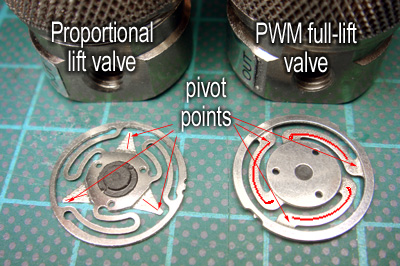
Proportional lift type:
(Chopped DC (~400Hz) or DC current)
This type of valve resembles the action of a rotary water tap. As more current is applied to the valve coil, the higher the valve lifts from the seat. It is a very nice way to control flow.
There are a few minor problems associated with this type of valve: Atomisation at low flow (see paragraph below) and lift variations (hystersis of the magnetic circuit), approximate +/- 10-15% flow deviations.
All in all, it will deliver liquid well compared to the PPS system. There are some similarities between the two. The nozzle tip pressure is directly proportional to the flow. This is because the proportional valve acts like a variable restrictor upstream of the nozzle tip. Resulting in: restricted flow = low pressure. Low pressure = low atomisation.
----------------------------------
Summary:
It is important to know some basic facts between the two PWM valve systems before choosing this type of system.
Here is an illustration of the difference in construction of the two valves, made by Clippard. Notice the "PWM" (full "on/off) has a softer spring rate than the "proportional lift" valve, enabling the PWM valve to perform "full on" and "full off" positively.
Because the way the PWM system meters its flow based on a simple pulse width, it is very accurate. Further precision can be increased by introduce a suitable RRFPR to maintain Manifold pressure against manifold pressure. It is also possible to factor in a small duty cycle increase to the valve relative to boost increase.
Final consideration: If you are planning in future to create your own MAP via a third part system - only the "PWM-valve" can be driven directly by the ECU, matching the principle of a modern "fuel injection system" in every respect. Warning, before rushing off making your own system, Clippard valve is only rated up to 100psi, even with the smallest orifice version. The larger orifice type can only sustain 25psi. Multivalve is needed for flows over 500cc/min. Lastly, the valve mentioned has a typical 4mS on and 4mS off time.
END
-------------------------------------------------------------------------------------------------------------------------------------------

To be continued...
1st January 2008- updated
It is my attempt of explaining how different type of systems work and its advantage and dis-advantage, based on current systems offered. It is a my view and findings, please do chime in and discuss.
1) Single-stage
2) Two-stage
3) Progressive Pump Speed system (PPS)
4) PWM Valve controlled system
5) System that will integrate well with third party controllers.
6) Direct port
-------------------------------------------------------------------------------------------------------------------------------- -
The single stage:
The single stage WAI (water alcohol injection), as the heading implies, is not as basic as most people expects. It some cases, it will out perform a two-dimension progressive system. Please do not underestimate it. I will try to explain briefly why after the next few paragraphs.
Having a single trigger point and a fixed flow rate, one will get to know its effect on your engine very quickly. Due to its consistent repeatability, it is very easy to tune. This type of system is normally set to start spray in the peak torque region, where the engine is most likely to knock.
As the RPM climbs, the ratio of water to mass air tends to decrease. This may not be a bad thing because the tendency to knock is also lessen as the wastegate starts to open and prevent the boost pressure from increasing further. The volumetric efficiency of the engine also decreases as RPM climbs, breathing in less air. This also has the effect of reducing the engine's tendency to knock, demand of WAI flow is less. Unfortunately some engines do require continuous WAI flow at higher RPM due to heat build up through friction and turbo efficiency.
A 2-D pump speed system based on manifold pressure is a little bit tricky to tune compared to the single stage system. The user has to set the start and finish pressure points, those points are sometimes set at a considerable distance apart. Matching those operation points in a 3-D environment such as RPM/Boost ramp (nonlinear) is quite difficult. We will be discussing it in more details later.
FOR:
1) Low cost, simple and dependable.
2) Easy to tune
3) Very effective on a stock factory set up with a few pounds of boost extra.
AGAINST:
1) Dynamic operating range is narrow, may not be as effective on a high RPM knock suppression.
2) For high power/ high % alcohol applications, considerable fuel has to be taken out (boost clamp) to make the afr tolerable. Some sort of failsafe mechanism is necessary to prevent engine destruction when the WAI fails to delivery the correct flow.
END
----------------------------------------------------------------------------------------------------------------------------- -
The 2-stage system
(2nd September 2007)
----------------------------------------------------------------------------------------------------------------------------- -
The 2-stage system
(2nd September 2007)
At present, adding a second manifold pressure switch to active an additional solenoid valve at a higher manifold pressure is the definition of a 2-stage system.
This arrangement gives the system greater flexibility as well as extending the flow range. It addresses the problem associated with the single stage system, too much flow at the start and not enough when RPM climbs beyond the wastegate setting.
As the system is based on boost trigger, it still won?t address the RPM related flow. For a turbo charge engine, the most significant active regions are the boost ramping stage and engine?s maximum torque range. A two-stage system fits these two regions nicely, allowing the some form of cooling demand during the ramp-up stage. The second stage provides the in-cylinder cooling and knock suppression as the engine is under the most stress or highest BMEP (Brake Mean Effective Pressure).
FOR:
1) Relatively low cost to give mark improvement to the single-stage system.
2) Provides well defined triggering points during the boost cycle.
3) Minimising the under/over flow problem.
AGAINST:
1) Trigger points requires some time to set up.
2) Triggering points may differ on each gear if you have a fast spool up turbo
3) Require a bit more care during tuning
END
-------------------------------------------------------------------------------------------------------------------------------------------
-------------------------------------------------------------------------------------------------------------------------------------------
Propressive Pump Speed system (PPS)
(2nd September 2007)
(2nd September 2007)
Does the pump speed controller perform better than a two-stage system, you are about to find out.
Changing pump speed merely put more pressure behind a nozzle, hence more flow. This type of system is commonly known as a progressive system (pump-speed).
Let us examine how much a M5 nozzle will flow between 40psi to 160psi. According the chart below (Published by Hago, a well know US oil heater nozzle manufacturer), the flow starts from 200cc/min and ends at 400cc/min., when pressure is increased from 40psi to 160 psi.
Almost all PWM pump controller on the market uses Shurflo pump, designed to operate between 0-150psi. The heart of the system is an electronic motor speed controller, vary the speed according to a sensor. It could be a MAP sensor, a MAF or any sensors that read engine load. It is normally a 2-dimensional system. A manifold-pressure type system does not take into account of any RPM change.
A swirling type atomising nozzle requires a head pressure of at least 30psi to produce a decent mist. Droplet size is very important to the inlet cooling ability and even cylinder distribution. Let say the system pressure starts at 40psi (as shown on the chart) and ends at 160psi. One can assume you will get a 4x flow range? In practice, not so, according to the chart, you will only get a flow change from 200cc/min to 400cc.min (see M5) instead of 200cc/min to 800cc/min. Flow/pressure obeys the square-root law.
Being "progressive" implies a reasonable dynamic range between start and finish. How progressive? Almost no one ever questions this. Most people just assumes it covers all the flow requirement between 10psi to 20 psi of boost once the range-dials are set on their pump speed controller. In practice, you cannot expect the same M5 nozzle will serve a wider operating range between 5-25psi by merely changing the dial, the range is governed by the law of physics and not a technically advanced motor speed controller.
If one would want to delve deeper into the subject, as the title demands. So the subject will continue?
Just to recap, good dynamic range (pressure/flow span) is the main factor one should expect from a "progressive" WIA system. Let see what a 150psi system can really offer. We shall take into account of the effect of manifold pressure, inline checkvalve as well as minimum pressure for a good atomised spray.
For example:
1) Manifold pressure start: 10psi
2) Manifold pressure ends: 20psi
3) Inline checkvalve crack pressure: 20psi (updated)
4) Minimum pressure of the atomising nozzle:40psi (Hago chart).
When the system starts: it will instantly see an initial back-pressure of 60psi and a final back-pressure of 70psi (extra manifold pressure). The actual dynamic pressure range is now from 60psi to 110psi. The system can now only manage a 35% change in flow, far from one would imagine a 150psi pump system should perform.
There are other factors that could also affect the performance of the 2-D progressive pump system. It may be a subject for a later discussion, depending on the interest of the readers. Chart below is a predicted performance of a progressive system compared to a single and two-stage system. I hope there will be people chiming in to add to this. At first glance, it doesn't appear there is a distinct advantage for adding a progressive controller. Adding a bigger nozzle doesn't alter the dynamic range, it just shifts the whole curve higher.
FOR:
1) Easy to set the start and end point.
2) Some correlation between manifold pressure and flow
3) Cost effective.
AGAINST:
1) Limited dynamic range, system becomes less effective after wastegate pressure. (see addendum)
2) Extra cost can easily be spent on a higher performance two-stage system with greater dynamic range .
3) If the 2-D system is used to replace high % fuel with alcohol, re-mapping the 3-D fuel map will be very difficult due to the wide dynamic flow range demanded by the engine.
4) Pulsing due to demand switch ~20psi ripple. (some system by-pass this switch, but risking system pressure beyond design limits). May require further explaination
5) Response time due to inertia of a rotating - laggy (start) and over-run (stop). May require further explaination
END
---------------------------------------------------------------------------------------------------------------------------------------
---------------------------------------------------------------------------------------------------------------------------------------
PWM valve water injection system:
These systems require a stable system pressure, normally held between 100-125psi. An inline solenoid valve and a PWM controller that modulates the opening and shutting time to meter flow. Before getting too deeply into the subject, note that there are two types of inline solenoid valves on offer.
Type #1
Pulse width modulation type:
(Optimum operating frequency range: 30-80Hz)
(Optimum operating frequency range: 30-80Hz)
This type of system resembles the modern automotive fuel injection system. The system can also be controlled by a third party EMS with a spare PWM channel. Delivery rate can either be mapped or mirroring the fuel injector duty cycle. The latter makes tuning very simple.
The valve behaves similar to an on/off gated button on a garden hose. The longer the gate is opened, the more the flow (duration). Alternative, rapid opening/shutting the gate per second (frequency) also control the flow. The common EMS uses duration for load change and frequency for RPM change. The dynamic flow range is extremely wide, 100:1 is normal.
A WAI valve should closely match the closing and shutting characteristic of a fuel injector. This is important for fuel flow mirroring algorithm since the modern EMS has a correction stage to compensate the opening delay and shutting delay.
-------------------------------------
Type #2
Proportional lift type:
(Chopped DC (~400Hz) or DC current)
This type of valve resembles the action of a rotary water tap. As more current is applied to the valve coil, the higher the valve lifts from the seat. It is a very nice way to control flow.
There are a few minor problems associated with this type of valve: Atomisation at low flow (see paragraph below) and lift variations (hystersis of the magnetic circuit), approximate +/- 10-15% flow deviations.
All in all, it will deliver liquid well compared to the PPS system. There are some similarities between the two. The nozzle tip pressure is directly proportional to the flow. This is because the proportional valve acts like a variable restrictor upstream of the nozzle tip. Resulting in: restricted flow = low pressure. Low pressure = low atomisation.
----------------------------------
Summary:
It is important to know some basic facts between the two PWM valve systems before choosing this type of system.
Here is an illustration of the difference in construction of the two valves, made by Clippard. Notice the "PWM" (full "on/off) has a softer spring rate than the "proportional lift" valve, enabling the PWM valve to perform "full on" and "full off" positively.
Because the way the PWM system meters its flow based on a simple pulse width, it is very accurate. Further precision can be increased by introduce a suitable RRFPR to maintain Manifold pressure against manifold pressure. It is also possible to factor in a small duty cycle increase to the valve relative to boost increase.
Final consideration: If you are planning in future to create your own MAP via a third part system - only the "PWM-valve" can be driven directly by the ECU, matching the principle of a modern "fuel injection system" in every respect. Warning, before rushing off making your own system, Clippard valve is only rated up to 100psi, even with the smallest orifice version. The larger orifice type can only sustain 25psi. Multivalve is needed for flows over 500cc/min. Lastly, the valve mentioned has a typical 4mS on and 4mS off time.
END
-------------------------------------------------------------------------------------------------------------------------------------------
To be continued...
 02-15-09, 06:05 AM
#2
Senior Member
Thread Starter
Join Date: Sep 2006
Location: uk
Posts: 402
Likes: 0
Received 0 Likes
on
0 Posts
Addendum: Knowing the heart of a WAI system: The pump
It appeared Shurflo is the main supplier of the majority of water/alcohol injection systems makers. So it is more appropriate to take a good look into them first. You will be amazed to know how many pump variations Shurflo offers over the standard "off the shelve" configuration. I was told it has over 300+ "custom" configuration is still active.
Pump motor:
Currently, there are three frame sizes: short, medium and long stack, covering three power ratings of 60W. 100W and 150W.
Pump cam angle:
Cam angle dictates and governs the final specifications of pump's flow rate, pressure. Shurflo offers: 2, 2.5, 3.0, 3.5 or possibly more profiles. Depending on the application, WAI makers can select the most suitable cam for their system.
At first glance, using the highest lift cam will produce the most flow and pressure. But if this cam is matched with a small motor, it will cause undue stress on the motor winding. This is very similar to going up a steep incline on high gear where the car's engine and gearbox is being stressed.
On the other hand, a low cam angle will produce less pressure and flow. Some PPS manufacturers prefers using the lower angle cam because of the following (as long as it delivers the specified flow) :
1. Less stress to the diaphragm - long term mechanical reliability
2. Less stress to the motor - lower running temperature.
3. Within a flow range up to 1000cc/min or so, there is ample pressure generated to hold the system at 150psi.
4. A much smoother control range from a PPS controller. High cam lobe tends to ramp up too much pressure with the same duty cycle applied -making the ramp-up abrupt - similar to using 2nd gear to get the car moving.
5. The pressure spike is also much smaller, this allows the peak pressure closer to the "150psi demand switch". Overshooting will cause the infamous "pulsing" often associated with a PPS system.
Note: a system advertised as 150psi@3 litre/min may NOT out-perform a 150psi@1 litre/min system. Often, the latter is a much better system. As far as the raw material cost difference is concerned, there is NONE. In these days, hypes rules the market.
By-Pass pump (no demand switch):
Shurflo Offers a huge range of internal by-pass valve to overcome the necessity of using a "demand switch" . Excess pressure is being "by-passed" internally by a set of spring load poppet valves (x3).
This type of configuration is more suited for PWM valve system rather the PPS system. The pump is switched on just before injection, attains a "steady" line pressure continuously through out the entire delivery cycle.
Only a very small numbers of PWM valve WAI manufacturer uses this set up.
Regulating pump pressure steady (with on-demand switch):
Other than employing the bypass valves, the water pressure can be limited by using an "on-demand" switch. This method is simple, every time the pump hits the "set pressure" of the on-demand switch, the 12V feed to the pump is interrupted. Shurflo recommends this method should only be applied to application where the usage is intermittent and not cyclic use.
Against the recommendation, there are WAI systems on the market employ this technique to control water pressure. Most PPS systems only hit this pressure at peak injection pressure intermittently so long term damage to the pump is not severe. Pressure spikes of 20psi+ exists.
If this method is being used to regulate water pressure on a PWN valve system, it is a completely different story. The "intermiittent" use now becomes " cyclic" usage. This will create long term problem on the switch as well as the pumping mechanism. Water pressure will also suffer from pressure spikes, sometimes as much as 20+psi spike. Using a low hysteresis switch may reduce the ripple but the other half of the problem still remains.
to be updated...

 02-15-09, 02:30 PM
#7
Senior Member
Thread Starter
Join Date: Sep 2006
Location: uk
Posts: 402
Likes: 0
Received 0 Likes
on
0 Posts
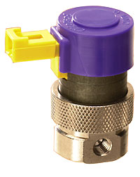
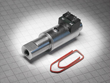
Aquatec (www.aquatec.com) pump will be used by many WAI systems from now on. We have been testing them and so far the results are good. Here is a picture of the pump putting next to the Aquamist pump.
We will be using the pump at ~160psi on the new HFS-6osa system.

We will be using the pump at ~160psi on the new HFS-6osa system.
Trending Topics
02-15-09, 07:18 PM
#8
Senior Member
Thread Starter
Join Date: Sep 2006
Location: uk
Posts: 402
Likes: 0
Received 0 Likes
on
0 Posts
Addendum: Action of a check valve under dynamic conditions:
Almost all progressive systems use a checkvalve between the pump output and nozzle for the reasons listed below:
Positive effects (well documented):
1. Retain some pressure in the line to compensate the next injection event. A 20psi loaded checkvalve will keep 20 psi of pressure in the line after injection.
2. Stop water being siphoned into the engine if the water jet is installed in the vacuum side of the manifold.
3. Prevent emptying the entire tank into the inlet tract if the tank location is higher than the jet (gravity fed) or the car is parked on an incline.
4. Stop some dribble after an injection event. Even when the power of the pump is switch off, the inertia of the rotating mass keeps the pump running for a second or so.
Negative effects (less well documented):
5. The presence of a checkvalve has a very significant impact of the dynamic range of a 150psi progressive pump speed system. A 20 psi checkvalve inline will instantly drop the 150 PPS system down to a 130psi span.
6. A normal nozzle requires ~30psi for produce a decent atomised spray. An inline 20psi checkvalve means the pump has to produce 50psi to produce a decent spray.
7. Let say the PPS system�s starting point is at 12psi boost, the system will now require 62psi to produce a decent spray. Some vendors will tell you a check valve will not impede flow once it is opened, true. But it will tax the pressure heavily where the PPS system relies heavily upon.
8. When the PPS system arrives at 24psi boost (end point) manifold pressure, the dynamic pressure is now further taxed. Before not too long later the dynamic range of a PPS system is now from 62psi to 126psi � translate it to flow: 176cc/min to 326cc/min, a mere 84% percent increase.
9. I have taken some data from a reputable PPS system manufacturer, a 150-psi 60W Shurflo flow pump has the follow characteristics:
Most important thing to remember, nozzle size determines output pressure (updated on the 21st January 2008) .
M1 (not tested)
M2 230psi
M3 225psi
M3 215psi
M5 190psi
M7 180psi
M10 170psi
M12 (not tested) did not have one handy.
M14 155PSI
From the figures above, the pump is only capable of sustaining 135psi system pressure on a M5 nozzle. Despite claiming the pump is capable of flowing one 3-4 litre per minute, conveniently missing the pressure parameter. The above PPS system maker is the only one that published these figures in public � thumbs up for them.
NOTE: The above data is from one maker only (as stated) Please read post #3 to understand why different WAI makes uses differ pumps, some make more flow and pressure than others.
Summary:
Some PPS system makers are now offering an inline solenoid upgrade so that the dynamic range is improved by a good margin. Not sure why they didn�t include it in the kit at the beginning. Many PPS systems run their pumps up to 200-300psi - something I have questioned Shurflo, they said NO, NO and NO - no "ifs" or "buts". They are looking into a higher pressure pump but not yet done and will not be released until they are comfortable with it. I have a meeting with the Shurflo's director of engineering at our works two months ago during his UK visit - he confirmed the imaginary 200psi+ pump (8000 series).
Here is an illustration of the above in graphical form:
Bench test set up of a 8-psi checkvalve
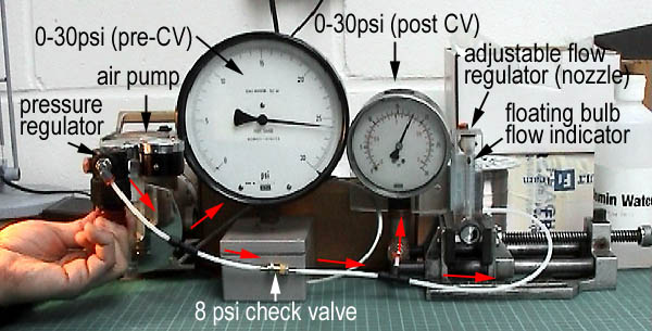
Video is ready to be viewed: Click here
(ONLY works with Microsoft IE)
Download video: Click here
Here are abner's Check valve test - please be patient, video files are about 5MB
NO CHECK VALVE (see video)
Download (1.78MB): Click here
ONE CHECK VALVES (see video)
Download (4.40MB): Click here
TWO CHECK VALVES (see video)
Download (3.86MB): Click here
The final flow quantity should give you some clues on the effect of the CV.
---------------
Bench test set up of a 8-psi checkvalve
Video is ready to be viewed: Click here
(ONLY works with Microsoft IE)
Download video: Click here
Here are abner's Check valve test - please be patient, video files are about 5MB
NO CHECK VALVE (see video)
Download (1.78MB): Click here
ONE CHECK VALVES (see video)
Download (4.40MB): Click here
TWO CHECK VALVES (see video)
Download (3.86MB): Click here
The final flow quantity should give you some clues on the effect of the CV.
---------------
02-18-09, 09:25 PM
#10
02-19-09, 08:19 AM
#11
Senior Member
Thread Starter
Join Date: Sep 2006
Location: uk
Posts: 402
Likes: 0
Received 0 Likes
on
0 Posts
Howard,
As far as I know, they are methanol resistant, or compatible. For a purist point of view, no rubber part is totally immune to deterioration when 100% methanol is used. Rubber is basically a long chains of hydrocarbon molecules. Alcohol will strip some of the oily surfaced away with time, eventually shrink in dimension. I expect it will take a year or two to becoming a problem.
So far the pump is holding up to 160psi. But when I turn it up to 200psi, the by-pass valve is having some problem holding the line pressure steady.
I spoke to the maker aquatec, they are very pleased that we are only running the pump at 160psi or so. The pump is slightly better than the shurflo in term of current drawn to sustain a given flow/pressure demand - more efficient. Perhaps a strong permantent magnet was used.
02-19-09, 08:34 AM
#12
Senior Member
Thread Starter
Join Date: Sep 2006
Location: uk
Posts: 402
Likes: 0
Received 0 Likes
on
0 Posts
It is sometimes too much to ask a checkvalve to do the job of a Solenoid valve. Some PWM system needs a checkvalve if the nozzle is some way from the valve. it keeps the water inside the line, minimising the delay on the next injection event.
The crack pressure of a checkvalve should be tailored to your application. Too high a cracking pressure will rob you of pressure seen at the nozzle tip. A weak valve will leak under partial vacuum, even on the non-vacuum side of the throttle plate. This is caused by force of gravity (tank is higher than the nozzle, parked on a slope etc.) or venturi effect in the inlet track.
A solenoid is normally good for holding up against a 100psi+ of pressure compared to a common checkvalve at ~20psi. When a solenoid opens, it does not drop as much pressure as the Checkvalve. Sometimes may be a few psi.
All in all, try avoid using it for major work or you may end up a engine full of water. The cost between the items is only a few dollars, why compromise.
02-19-09, 08:58 AM
#13
Racing Rotary Since 1983
iTrader: (6)
Richard,
yes, it seems the key qualifying word is always "resistant" when it comes to alcohol. Bosch uses the same "R" word.
as you may know, i run an FJO twin 700 CC/Min system. i am a beta tester. initially, i ran FJO's Shurflow pump along w 100% methanol. i set the line pressure at 115 psi. the system both reads and logs line pressure.
i found both on road testing and dyno testing that under actuation the pressure decreased from a stable pressure. not good.
FJO indicated that the line pressure did not vary using pure water or a 50-50 mix. they indicated that the pump was creating meth vapor/cavitating when the solenoids were closed.
i did a re-do. i switched pumps to a lower outputting Bosch 044 variant, the 909. i fixtured a Weldon adjustable pressure regulator and i added a return line.
i went back to the dyno, set the line pressure at 110 and did 23 4th gear 2000-8200 runs w zero pressure variance. after a few runs we didn't even think about the AI system which is exactly what i want.
if i have the time, i may re-plumb the FJO Shurflow pump so as to support their system. i think it will work just fine.
i found it very interesting that alcohol will vaporize and the mix will not. i understand that perhaps a bypass in the Shurflow pump might also have solved the problem w alot less $ and effort but i just decided to do it my way.
here's my question to you Richard...
it is the 21st century and AI systems should be run either in parallel w the base fuel table... that is, exactly copying the base fuel injectors... (like your FD summer)
or
as the FJO system delivery should be able to be set on an X Y grid w Load and RPM.
delivery should not come from pumpspeed/nozzles.
can you imagine if your car had it's base fuel run off a variable speed pump and a nozzle?
in addition to not being linear w increasing voltage which you so excellently showed... what is the response if you are modulating the throttle in boost? can you imagine that a pump could bob and weave w your right foot? not a chance.
so just tell me this...
your new system and the FD.
does it require the summer?
does it offer an X Y grid (Load and RPM) with cells in which to stipulate either Ms ontime or % of solenoid deliverability?
also, slightly off the above topic, what is the max deliverability of your solenoids? most 100% meth users should be running two 700 CC/Min solenoids.
howard
Last edited by Howard Coleman; 02-19-09 at 09:09 AM.
02-19-09, 09:29 AM
#14
On flats
iTrader: (29)
Join Date: Oct 2004
Location: Albuquerque
Posts: 1,379
Likes: 0
Received 0 Likes
on
0 Posts
Howard,
Your questions regarding the new Aquamist system are answered in here :
https://www.rx7club.com/auxiliary-injection-173/aquamist-hfs-5-will-replaced-hfs-6-2009-a-819210/
In short:
Does it require the summer?
For non-uniform injector setups like pretty much ALL rotaries, yes. UNLESS, you drive the high-speed valve (HSV) using a PWM driver. Then you can map the delivery however you'd like.
Offer an XY grid?
Richard can better answer, but with even the last systems, one could do this with their standalone using a PWM driver for the HSV. I think Aquamist's "default" setup is better than that though. Using the FIDC, it sprays proportionally to your fuel. Basically, you want X% water/alcohol to fuel, you set that and it maintains it with ZERO further tuning. The new system has boost proportional and other trims if you wanted to ramp up your % vs various parameters as well. Again, the HSV can be PWM driven, so you can provide whatever map you'd like for delivery, I just think that the way the system is designed to mirror FIDC makes it SO much easier to use.
Delivery?
Again, Richard can correct me, but if memory serves, one HSV is good for ~1L/min. . .
02-19-09, 10:09 AM
#15
Senior Member
Thread Starter
Join Date: Sep 2006
Location: uk
Posts: 402
Likes: 0
Received 0 Likes
on
0 Posts
Howard,
Calculon was spot on regarding the new system.
As we are moving into the 21 century, electronics has been making mechanical part less important. You have successfully stablise the effect of manifold pressure by adding a mechanical pressure relief valve.
We have chosen a different route, may not be perfect but it goes some way towards compensatng the variation between the manifold and methanol line pressure. The HFS-6 has an additional trimmer over the previous HFS-5.
This little trimmer (boost compensation) monitors the manifold pressure and "inject" a small percentage of DC% into the final output. Works a bit like an air temperature compensation circuit. I can go into this in more details when I have a bit more time.
We did have a system with XY grid, during the early 20th century - it has a grid of 128 x 64, totalling 8000+ cells.
Here is an example of the map.

If the X-Y system proved to ne popular, we might offer this system again.
Calculon was spot on regarding the new system.
As we are moving into the 21 century, electronics has been making mechanical part less important. You have successfully stablise the effect of manifold pressure by adding a mechanical pressure relief valve.
We have chosen a different route, may not be perfect but it goes some way towards compensatng the variation between the manifold and methanol line pressure. The HFS-6 has an additional trimmer over the previous HFS-5.
This little trimmer (boost compensation) monitors the manifold pressure and "inject" a small percentage of DC% into the final output. Works a bit like an air temperature compensation circuit. I can go into this in more details when I have a bit more time.
We did have a system with XY grid, during the early 20th century - it has a grid of 128 x 64, totalling 8000+ cells.
Here is an example of the map.
If the X-Y system proved to ne popular, we might offer this system again.
02-19-09, 10:40 AM
#16
Darkside FD
Join Date: Jan 2004
Location: AZ
Posts: 1,175
Likes: 0
Received 0 Likes
on
0 Posts
I want to thank you for your input Richard. Even though I dont run FI with AI anymore, I still keep up with the trends because some day I will return!
 02-19-09, 02:20 PM
#18
Racing Rotary Since 1983
iTrader: (6)
Coz,
just put a rotary back in your car. i will build you a killer motor and even throw in your stationary gears! (which are A1 BTW)...
Richard,
yes, i clearly remember your grid and the point you made about it enabling the user to trim the AI injectant after peak torque at constant boost. at the time you had too small a pump for my methanol.
i do agree w you that paralleling the FIDC is a perfect way to command the AI injectant delivery. do have solenoids w 700 CC/Min capacity and can your setup drive two?
regards to all,
howard
02-19-09, 02:27 PM
#19
Darkside FD
Join Date: Jan 2004
Location: AZ
Posts: 1,175
Likes: 0
Received 0 Likes
on
0 Posts
Howard, Thanks for the offer! Might take you up on that a while into the future.
I am thinking about getting another FD... waiting for another one with the right components to hit the market. We will see. Might be a little higher probability that I end up with an Evo or WRX STi or even an FI BMW, so that I can play with some of Aquamist's products.
Can't get rid of my current FD though. WAY too much fun!
It sucks loving both setups (v8 and rotary) when you can't have both.
02-19-09, 03:17 PM
#20
Darkside FD
Join Date: Jan 2004
Location: AZ
Posts: 1,175
Likes: 0
Received 0 Likes
on
0 Posts
Ideally I would want to run two systems. One with Methanol only and one with water only. The water would cool the combustion chamber/slow the flame front. I would have the water injected in the upper intake manifold toward the incoming charge, and possibly pre-comp as well. I would inject the methanol in the intake tract after the compressor for max cooling benefit.
This way I could run WAY less methanol, and still get the positive...and I could run water where it mattered most and get the max benefit in chamber, as well.
Expensive, but it would be interesting. If I still had my HFS-5...I would buy the HFS-6 and run them parallel to see what we could get. ie. See if it is a good idea or not.
I dont know... just something I thought about.
I also would like to run a air/water intercooler like the ones from Lindsay Racing. Running those with a nice AI setup could yield some good results I think, and solve the space/cooling problems of the FD.
02-19-09, 03:37 PM
#21
Senior Member
Thread Starter
Join Date: Sep 2006
Location: uk
Posts: 402
Likes: 0
Received 0 Likes
on
0 Posts
.
.
.
Richard,
yes, i clearly remember your grid and the point you made about it enabling the user to trim the AI injectant after peak torque at constant boost. at the time you had too small a pump for my methanol.
i do agree w you that paralleling the FIDC is a perfect way to command the AI injectant delivery. do have solenoids w 700 CC/Min capacity and can your setup drive two?
regards to all,
howard
.
.
Richard,
yes, i clearly remember your grid and the point you made about it enabling the user to trim the AI injectant after peak torque at constant boost. at the time you had too small a pump for my methanol.
i do agree w you that paralleling the FIDC is a perfect way to command the AI injectant delivery. do have solenoids w 700 CC/Min capacity and can your setup drive two?
regards to all,
howard
Our inline valve is rated at ~1000cc/min at 160psi. We now manufacture them ourselves, brass body casting is sub-contracted. We didn't want to increase the flow too much and have to throttle it backdown wrth restrictors. This was what we were doing with the old HSV. It just flowed to much for this market.
The new valve has its own driver inbuilt within its own enclosure . It need only singal level to drive them from the main controller, just several milli-amps. It means that you can expand it, as manya as ten to twenty valves. But we have not yet make it available.
02-19-09, 03:45 PM
#22
Senior Member
Thread Starter
Join Date: Sep 2006
Location: uk
Posts: 402
Likes: 0
Received 0 Likes
on
0 Posts
Howard,
I have been following your project, it is by far the most reliable and accurate system I have seem. I like to offer that but just proved to be too good and complex for mass market. This just like a secondary fuel system, short of using fuwel injectors.
I think most people might like to fill the tank with E85 and done with it. I hate to ask, will you be moving on to a direct port? You are only a hair-width away from it.
02-20-09, 01:33 PM
#24
Senior Member
Thread Starter
Join Date: Sep 2006
Location: uk
Posts: 402
Likes: 0
Received 0 Likes
on
0 Posts
Dynamic range of a 250psi system on a M5 nozzle
Topic of discussion:
David of Collingmist would like to discuss his claim of achieving
~700cc of water flow from a 250psi pump on an M5 nozzle.
He disputed my of claim of "approximately x2 dynamic range" from a pressure change between 60-240 psi.
Here is a screen shot of his post:

David of Collingmist would like to discuss his claim of achieving
~700cc of water flow from a 250psi pump on an M5 nozzle.
He disputed my of claim of "approximately x2 dynamic range" from a pressure change between 60-240 psi.
Here is a screen shot of his post: