When you click on links to various merchants on this site and make a purchase, this can result in this site earning a commission. Affiliate programs and affiliations include, but are not limited to, the eBay Partner Network.
All of the "boring" optimizing is done, now it gets easier and a bit faster-paced, as that last stage was quite a slog. Color work is being handed off later today so I can get all of the connectors split up and optimized in each section.
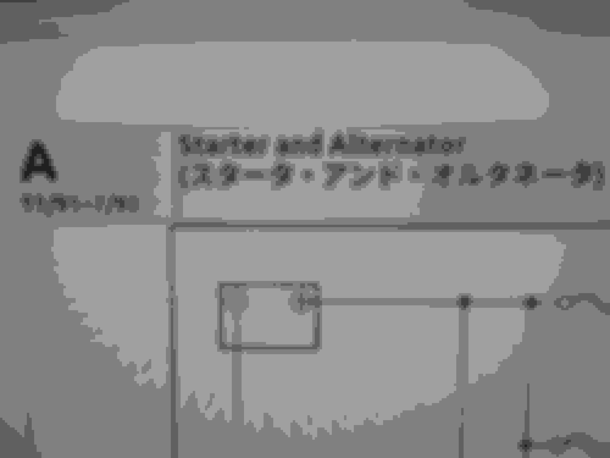
Section A and B already have their color put on, so they're ready for compile once the connectors are all finished. With all of the detail work going into the project, this 27" screen is definitely earning its keep.
Once compiling begins, no more discounted preorders will be accepted. So this is your early warning. If you have a RHD FD, it's your last chance to save $100 on something you'll need one way or the other.
So I've received a few questions regarding how to preorder for the discounted price of $200 USD. The simple answer is to just message me (facebook usually gets a quicker response). I generally like to discuss your needs and expectations before accepting any payment via paypal, to ensure there's no misunderstandings. Also, with your VIN number, I can run a Build Sheet for your car to answer any questions regarding labels/parts/etc specific to your car. It also curtails most "which diagram do I use?" type of questions in the process by pinning your car down to the exact day it was made, the exact model, and specific options it had from Day 1.
A good example of this is with the ABS System. Before July 1994, the Hydraulic Unit had 3 solenoids (front left and right, plus rear), just like the FC3S GT-Limited Special Edition. Even uses the same tools to diagnose too. In July 1994, it was upgraded to 6 (hold and release for each channel). And in September 2000, the system was changed again to combine the electronic and hydraulic parts together into one unit. This was likely done to cut costs a bit, eliminating quite a few wires that ran about 3/4 the length of the car that the Control Unit used to power and operate each solenoid. Presumably, the 9/2000 system has six solenoids like the 7/94 one, but a donor unit would have to be sourced and disassembled to confirm it beyond reasonable doubt.
Each of the three systems has specific supporting parts such as harnesses and Control Units that all have to match in order to function correctly.
With that said, here's the latest:
Rested up for a couple days and hammered out the final formatting. Templates are done now, I had to create my own parameters from scratch. While doing so, I inadvertently exceeded the design limits of the Microsoft Word Document format. So OpenDoc to the rescue. Each page will need individually adjusted a bit to fit together the way I want them to, but everything is standardized to streamline final render and assembly as much as humanly possible.
Teaser shot. 27" screen at 2560x1440. 50% zoom and it BARELY fits. The actual diagram image was reduced to about 1/4 size when I rendered this.
At the normal 100% zoom, mouse cursor is the standard size for any Windows or Linux system
This test render ended up being ~900kb for a single page. And what you're thinking right now? That's exactly what she said...
Last edited by Akagis_white_comet; 05-17-23 at 10:07 AM.
Reason: Additional Update
So I just finished extracting images of every single connector ever used on any FD. 1885 of them, sorted into over 200 folders. About 15% of them were in Section X. That massive drag is done, and obligatory backups are made, now the moment we've all been waiting for. Compiling can begin now. Iffy connectors will be subbed out for a cleaner version whenever possible so everything is rendered at the best possible quality and clarity that I can do.
1885 connector images, 529 diagrams, and some misc oscilloscope ones in the ECU charts that I can't remember right now, and ALL of the text for it. I'm combining over 2400 files together. Good thing I got a new graphics card on ebay, gotta love those dirt cheap deals. So if all else fails, I'll have enough outputs for anything I could need for an excruciatingly long time, and up to 4k resolution on all of them.
Update time. So I took a few days to rest, recover and replenish. Got my new graphics card, went in without any fuss and it's earning its weight in gold already. With the same screen configurations, I found out I'm using roughly 330mb of video memory. My old setup was 256mb, so that explains why it was having problems and acting like it was having a seizure at times. So that's good to go.
I've been ironing out the last few images for things like ECU pinout charts so the clarity and quality is the best I can do. The meter/scope images portray the same data points for each item, and the S7/8 ones are ~50% higher resolution, so it sounds like a winner. A bug fix correction on the early TWS units was added in too.
These were the last things to be tidied up, so compiling is a go now.
So today is June 1st and I've started rendering each page. It's going in two steps, first is the Pre-Render to get all the images in their approximately final setup on every page. Once that's done and I can see the overall fit/finish, the finalized text can be put in and every piece adjusted so it all fits correctly on the page. I was going to start this yesterday, but got a little sidetracked after giving all of the page templates an overhaul for that extra bit of polish. I also drew up the Front Cover artwork too, but that's gonna stay a secret until everything is finished.
Ready for final text now.
And one last tweak. Production dates and Applicable VINs for each page.
So things went a little sideways regarding getting the main diagram/location pages pre-rendered. In the meantime while it is getting resolved, I've been working on the various pinout charts throughout the whole thing to get them ready for rendering. A consequence of this was that every chart was upgraded with the associated wire colors so they match the style, fit and finish of the N3Ax ECU Pinout chart. Makes it 10x easier to diagnose things too. The N3Fx (Series 7) ECU chart and the N3Gx (Series 8) supplement ECU Chart are merged together. Right now, I'm doing one final pass through to unify any odd wording in wire colors, then all of the waveform images will be put in and each can be split into individual pages.
One thing I did discover is that TWS Unit #1 is wired the same as CPU #1 on North American FDs. It's the interior fuse block's "backpack". TWS Unit #2 (AKA CPU #2) is a different story. All of the Japanese market ones have the same pinout and wire colors, with later ones being "dummied out" on removed features such as the key cylinder lights. I can't remember offhand if it is due to circuits being removed inside TWS Unit #2, if the harness had these items de-pinned, or if it was both. When I get closer to the finish line, we'll know more. On the other hand, North American CPU #2 has additional functions such as the Security Light and can interrupt the Starter too, so their connector pinouts were shuffled around and connector #2 has a few more pins added too. But from a quick glance, it MIGHT be possible to use a USDM CPU #2 on a Japanese FD.
Time to get back to work, it's gonna be a busy weekend.
And 8 hours later, ECU charts are nearing the finish line. Here's a test fit for size on the oscilloscope output and descriptor text. 12pt bold and plenty of space. Can go to 10pt if it gets cramped, but everything's looking good.
Gotta love high res images
Anyway, progress has undoubtedly been slower than expected so it looks like the June 30th date may not happen. I'm doing the best I can, it's just a LOT of work and this one is being made to a MUCH higher standard than the Wiring Diagram book I made for the Cosmo.
Last edited by Akagis_white_comet; 06-11-23 at 12:42 AM.
Reason: Midnight update
It's been a busy few days and I've been hard at work. Today was especially good as I finished the final render on all of the Pinout and Service Code charts. 51 pages finished and re-combined into their 17 respective sub-sections.
10% is finished now. Tackling the Flow Charts next.
I was up till 4am this morning, but the Flow charts and SRS text pages are finished now. Everything that isn't a diagram or location page is rendered and finished. 82 pages out of 500 done now. 16% done.
So the color work is finally finished. Now the fun stuff can begin. I'll be making a Test Build of the entire book this weekend to see how things fit and flow together, make any adjustments needed and get a page count to get in the ballpark on the final product.
So today is June 30th. As I'm typing this, my system is putting everything together right now. So in that respect, the date was met with...
The IKEA Edition! 2.9gb of pure awesomeness. Some assembly required.
Now that we've all had a good laugh from that, here's the latest. I just added all of the titles to every page and rendered all of them as PDFs for the Test Build. Took maybe 5 seconds longer per page to add that step. Everything has been given a final going-through, which caught a few minor errors that slipped past me before. The IKEA Edition has all of the necessary files to compile everything together in a single, yet massive package. Compiling this monster will be split 4 ways once the Test Build is done. So, 408 pages, plus charts, flow charts, text pages for Section S, and all the extras too. Hopefully it won't take too long.
Last edited by Akagis_white_comet; 06-30-23 at 05:45 PM.
Reason: correct file size
Tonight! A cat takes a nap! I get a concussion! And a file is made!
(cue Top Gear Theme)
So all of the above is true. Still not feeling 100%, but I put together the Test Build this morning to get an idea of what the final product will be. It's currently 532mb and 489 pages. A couple bits need tidied up and some other parts added, but we're at least in the ballpark now. Realistically, the final product will be in the 6-700mb range once all the text is added, bookmarks put in and all the other fun stuff.
Teaser now.
Time for a break. Concussion is not something to f*ck around with.
It's been about a week since the concussion and I'm trying to get work done still. I'm at roughly 25%, so I started hammering out the vacuum system diagrams as it's the "lightest" work I can do right now. It's taking a LOT longer than I'd like since I can only focus well enough for maybe an hour each morning. Between this and the back of my left shoulder/neck area aching, progress has ground to a crawl and there's just not much I can do about it.
On a different note, I got the POR-15 Fuel Tank Repair Kit (Aaron Cake used it on the 1976 Cosmo) for my daily a few days ago for $68. Advance Auto Parts had it on sale, then a coupon on top. Yay for half-price repairs
Hey everyone, sorry for the lack of news over the past two weeks. Recovery has been slower than I'd like, partly because I had been trying to chip away at work each day and it was working against me. I found that my VERY DEPOWERED focus just kept failing on me after maybe 30 minutes. So I threw in the towel for a week and gave my brain a rest. It's worked pretty well and I'm at roughly 65% of normal so work can resume. As long as I take a break when I need it, all should be okay.
Vacuum diagrams are roughly 80% done, I just need to verify the solenoid connector colors on a Series 7/8. Also took care of the Black Box disassembly/reassembly guide too. Might add a couple more bonuses, not sure yet. Anyway, I'm done for the day. Brain is tired now.
Well my internet has been down for almost a week, but I still got work done. During that time, I sorted out all of the connector images and put in "helper text" on each page. That way, I can outsource putting in the 1800 or so connectors where they need to go.
So a much-needed break was in order. Had to charge the battery in my BMW. Maybe 100ft from it, the spare tire carrier on my Expedition broke, dropping the spare tire in the middle of the street. It broke right where the cable meets the bracket. Thankfully, it happened on a side street at 20mph instead of on the highway at 55+. So now I get to figure out a solution. Yes, the whole thing CAN be replaced. But it's been in place since right before Mario Kart 64 came out, and rust is a thing. Better to pick and choose your battles.
While this happened, I spent a few days of my "break" sifting through the pile of mp3/audio files leftover from data recovery last year, getting it into some semblance of order. It's roughly 2/3 sorted, but a lot is missing and has to be found again. And there's a bunch that were renamed with numbers that I have to figure out what they are too.
Sorry I haven't been around much over the past week. Wifi JUST got fixed a day or two ago and I've been getting all of the pop-up projects like my spare tire hanger hammered out to get them out of my attention span. Ended up learning how to sandblast yesterday in 90+ degrees with a heat index of 110+. Not a fun time, but useful nonetheless. The bracket is in a vat of vinegar to finish breaking up the rust since it's too hot out to do any more sandblasting on it. Heat Stroke sucks.
I'm gonna get back on the FD Wiring Bible tomorrow to get everything dialed in for the final push on text and connectors. It's forecast to be in the expletive range of hot, so there's zero chance of me being outside. So I might as well be useful.
So the spare tire repair went a bit sideways after user error. One tiny bump and the cable end fell off because I didn't tighten it enough. Crank it back on and it's been solid ever since. Next, a trek to extract a fuel tank for my daily went sideways when the donor car wouldn't jack up straight. Then trying to find another donor tank went sideways too...
So it was today that I got a chance to sit down and get back to the FD Wiring Bible to fit connector images into place. And that went sideways too.
Most things went in fine, except the ECU connectors. No matter what I tried, it just looked off, wouldn't fit text properly or both. So I re-drew them all from scratch, did a test render and now they look and fit properly. It does mean a bit more work on the backend to put the terminal designations back in, but it also means easy matching with Ctrl+F (gotta love that feature!)
8 days and no update? So I made a script to expedite some picture edits. It's not perfect, but it will make things FAR quicker for doing the edits on the remaining 1500+ connector pictures. Still requires me to make a few keystrokes per picture, but take the whole task from a mind-numbing week down to a day of semi-auto action. Then they're getting sorted according to device to pick the best copy to use throughout.
Also, I've been busy after discovering my daily's negative battery cable wouldn't stay on the battery anymore and wouldn't tickle the starter. Crimped on a new lug and did the Aaron Cake treatment, still no crank. No crank and no fuel pump action. Got a broken power feed wire on the pump, and we're not sure what's wrong with the starter yet. Didn't get time to dive under the car to diagnose it, but everything before the starter checks out fine. Got a feeling it's from corrosion.
Edit: So I just finished the connector images. Just over 2 hours total. So the script works brilliantly
Last edited by Akagis_white_comet; 09-10-23 at 03:38 PM.
Reason: Ninja Update
After the daily driver debacle (yes it was corrosion), I got back to work here. The past few days have been spent sorting the freshly-trimmed up connector images into their associated devices.
It might sound menial, but there is a good reason for it.
5 "identical" images of Connector JB-09 on the inside fuse box. From top to bottom, we have 11/91, 7/93, 7/94, 12/95 and 12/98. There wasn't one for 9/2000 since no changes were made to it. Varying resolution, straightness, consistency and tidiness, no two are alike. So I can choose the best example of JB-09, make it perfect and use it throughout. Repeat for every other connector.
Only the 7/93 one came close to my standards. The other 4 all failed the test.
So I've begun the long process of mastering each connector and ran into a snag.
This is a comparison of X-04: Between Front and Engine Harness. It was re-named X-12 for North American FDs, but do you see what's wrong here? Version 1 (11/1991) is backwards from the rest of them.
I've noticed errors like this on the following connectors:
X-04
X-05
X-08
X-24 (Photoshopped in for this example)
Here are the locations for each of them, highlighted in yellow and red. Applies to all Japanese FDs.
There's enough of a doubt there that I need to verify those 4 connectors on each of the six sub-generations. I have a V1 (FD3S-1xxxxx) car lined up, but I need Version 2 through 6 to verify against too. If you can help, please message me or reply here so we can get this discrepancy straightened out.
Last edited by Akagis_white_comet; 09-25-23 at 12:10 PM.
Reason: fix formatting
Well, well, well, I never thought this would break into 5 digits but it has. And despite the minor snag from before, things are still moving forward. Right now, the finalized text is being put in for the connector pinouts, formatted and ironed out to a single standard to prep everything for the optimized connector images. For areas that were originally together that I split up for clarity, they're now color-keyed back together for easy reference. I just finished Section A in just under an hour, so it's going fairly quick.
Also, I've been working on a small side project here and there to help jumpstart new development. A Eunos Cosmo owner sent me their CCS Navigation disc so I could take a look at how it works. So I made a backup ISO and found it has no actual files on it and was rather small. Around 25mb, so it's definitely odd, but not unheard of. Took a look under the hood at its actual code and found there's a lot of similarity between it and an early Super NES rom or Playstation 2 save file. There's a TON of work to be done to fully decipher it, but it can be done now. A few areas I've identified are the Longitude/Latitude markers (same identifiers in the Workshop Manual), the disc header area, completion date (May 23, 1993 for this one) and what I suspect are an early form of Points of Interest at the end of the disc. A Repeating pattern of not-exactly-identical data blocks, 350 in total. From all of this, I'm thinking tht the CCS was coded in a way that the actual map data could be expanded on by having a larger "map block" and adjusting the Start Address for POI accordingly. The same trick was used in Earthbound to add more data for rom hacks (EB rom expander). Right now, this is purely hypothetical and will need quite a bit of work to figure out what makes it tick, how things are structured, etc.
While at it, a high resolution image of the label side was made too. Took a few tries to come out right since it's a "bare" reflective disc, and capture the hub code (like on a PS1 disc).
Have you compared the differences between the Series 1~3 and Series 4~6 wiring?
I found some major differences when tracing the injector wiring back to the ecu in the charts.
Also the wiring for the coils. I avoided disaster by checking the wire colours in the small coil harness to the proper coils.
The harness was hooked up in the reverse order!
Luckily we found this before the replacement coils and harness went into the car.
Yes, there are some differences as you mentioned. For this reason, going by wire colors/pinouts is the proper approach as similar connectors can easily be mixed up when in close proximity. Especially with the revised coil placement for 12/95+ (Version 4-6), things could easily go very wrong, very quickly from such a minor error. Fortunately, wire colors are generally consistent between early and late FDs so parts can be swapped between the two and wired up correctly without too much difficulty.
Right now, I'm trying to simplify the process as much as reasonably possible. As much as it sucks, I think it's time for a 3rd screen for organization purposes. My sub-screen had 10+ windows open on it when going through Section A and it was getting difficult to keep track of what I was working on. Between that and the 8 or so on the Main Screen, I found it was getting too time-consuming to sift through both screens to get what I needed. And it'll only get worse in Section B.
 05-15-23, 11:59 AM