When you click on links to various merchants on this site and make a purchase, this can result in this site earning a commission. Affiliate programs and affiliations include, but are not limited to, the eBay Partner Network.
I'm chasing a boost leak i have a tester where i can put pressure in the second turbo inlet, so if i get the ATC to shut and leave the ACC open this should help me find a leak right?
Can someone plz confirm that the metal end of solenoid a / pressure regulator goes to lim and the other vac port which points up and plastic goes to fpr?
Seems really odd that the fpr is hooked up to a solenoid.
I was on the FAQ for the 3gen rx7 and was trying to read Viton vs. Neoprene vs. Silicone and trying opening the site it gave which was http://www.geocities.com/MotorCity/G...5/hosetest.pdf but it redirected me to yahoo?
Can someone tell me why i should lose the stock vacuum hoses and get silicone or other types of hoses because idk which one is the best for a hot temperature city where i drive the car once a week about 50miles?
The stock vacuum hoses are rubber rubber and don't age or stand up to the heat very well. This causes the lines to dry out, Crack and not seal very well causing leaks at the connection points. Silicone is a better option because it's cheap and withstands the extreme temperature ranges of under the hood very well. It will remain soft and pliable for almost eternity. It's a much more reliable solution for our cars. The other materials you mentioned would probably be fine too but I can tell you silicone is the most cost effective and it comes in any color you can think of.
I conducted the accelerated long term vacuum hose tests and wrote that report over 18 years ago!!!. Bottom line, from the tests and as a mechanical engineer with 30+ years of design experience:
1. Stock Buta-N rubber hoses. - They will harden and eventually fail after about 10 years of normal automotive use.
2. Silicone hoses. - Have a much higher working temperature and will not harden under normal use. Plus, they come in so many pretty colors . However, from an engineering perspective, silicone is not compatible with ASTM Reference Fuel A, B, C, or D. And is not compatible with ASTM Oil 2, 3, 4, and 5. Doubters can check this chart. Yes, I know your personal experience with silicone trumps any standard materials engineering reference. My test with plain old Penzoil 30 weight confirmed that the silicone had some deterioration of the silicone bonds in the tubing exposed to hot oil.
3. Viton is pretty much impervious to most chemicals found in the engine compartment and will last longer than the car, but it is very expensive.
Editorial Rant:
I know everyone and their brother in the after market and in racing uses, sells, or hypes silicone hoses. However, no automotive engineer will specify it where they think it will be exposed to fuel or oil, and their company has to foot the warranty bills.
The question is, do you really need to buy fluoropolymer elastomer for your car? The answer is, probably not, remember even Buta-N hoses will last ~10 years and most of you will have sold your 20+ year old car long before that. Plus, now that the cars are older they aren't typically driven 20,000 miles a year, so any material will last way longer than you need it to. If you want pretty, go with silicone, if you want to save $ go with Buta-N, if you are just **** retentive (or a current or former Porsche owner ) buy fluoropolymer elastomer hose.
As a side note I have had Viton hoses in my RX-7 for 20 years and if you take one out, wipe it clean, you can't differentiate it from a brand new Viton hose.
Of course, the lengths of hoses in those diagrams are not to scale. So the diagrams are more scary looking than reality. Good to take many pics of your set up before pulling things apart.. And mark the hoses before you pull them off. Not that you are likely to break nipples off your solenoids, unless you are very careful.
Not sure what the deal was with the silicon hoses I got (from a reputable shop), but they turned to American cheese consistency pretty quick.
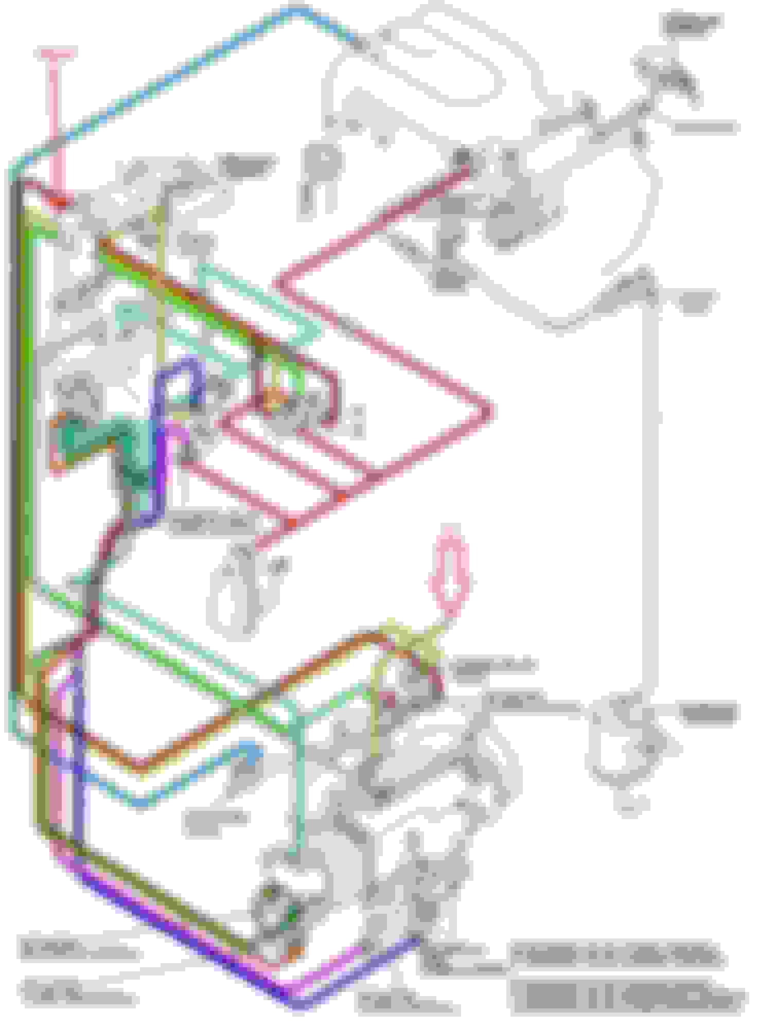
I am deep into redoing the vacuum system on my 94 FD in preparation for the installation of a new short block (arrives tomorrow). I'm also installing BNR stage 1 sequential twins. I've been using the following diagram: Simplified sequential twin vacuum diagram
Now that I am nearly done with replacing all the vacuum lines, I have some questions and would really appreciate constructive input: Question 1:
On the wastegate actuators it looks like the inlets at the 12 o'clock position simply have a small vacuum connecting the 2 wastegate actuators together. Is that correct?
Question 2:
The plastic elbow tube on the front of the front turbo has 2 inlets on it. It looks like 1 goes to a dark blue line which appears to go to the oil injectors. Is that correct? If so I'll just block them off as I plan to pre-mix on this car (I'm removing the OMP).
Question 3:
There is a fluorescent yellow line that goes from inlet on the cast aluminum tube on top of the turbos. Based on the diagram, it looks like that goes directly from the inlet on the cast aluminum tube on top of the turbos to the inlet on the inside/bottom front of the upper intake manifold. Is that correct?
Question 4:
I don't see on this diagram where the Double Throttle Control vacuum line is connected. Any suggestions?
This project would have been much easier if I had simply pulled the engine and then replaced each line. However, I pulled the engine and removed/cleaned everything in anticipation of the new short block.
Howdy,
1. Not quite, each of the 12'00 clock nipples should be connected upwards to a dual-nipple'd barb which protrudes from the primary turbo's outlet.
Don't judge how dirty it is in the picture, I'll clean it!
2. If I understand you correctly (the dark blue line right?) then the answer is 'sort of'... it goes up to a small triple-tee which then goes to the oil injectors as well as both boost control solenoids (solenoids 'I' and 'J'). You can see it in the diagram where the dark blue line turns into a 'blob' (right above where the vacuum chamber is pictured). If you're removing the OMP system, I'd just cap off the tap that feeds the oil injectors there on the tee.
3. There's a nipple way down in the LIM closest to the front side of the engine, that's where it connects.
4. The double throttle vacuum line gets routed to the double throttle solenoid. However, since your image is of a simplified sequential setup, that solenoid and its routing have been edited out. Haven't worked with a full (non-simplified) setup in a while, so that's where my knowledge of that part ends. Look up a full vacuum line diagram (non-simplified) and you should see it.
Last edited by XanderCage; Jan 5, 2020 at 08:15 PM.
XanderCage, thank you VERY MUCH for your help!!! You just received 100 karma points :-)
It would also be great if I could get confirmation on the following 3 lines. I'm not sure if it is clear in the picture, but this would be the front of the rats nest where there are 3 metal pipes pointed downwards.
This is the front of the rats nest on my 94 RX7
Could anyone please confirm if I have these lines marked correctly?
I believe the right line goes to the vacuum chamber
I think the center line goes to the pressure chamber
And the line on the right goes to the upper intake manifold where there are the 4 inlets (lower right position with a check valve installed)
Thanks very much for the constructive input. Really looking forward to having this part of the project done!
Oooh, 'fraid not. Not great at describing stuff but here goes- So, of those three lines, two are T'd from one hardline right at the end. You can see, the hardline of your vacuum chamber tube makes a sharp 90* bend and goes right into the one you have labeled 'pressure chamber'. That ain't right because the pressure from your pressure chamber will just rocket right into the vacuum chamber!
So in short, your line labeled pressure chamber and your line labeled 'UIM, Use check valve' need to be swapped. How it works then is that the check valve going to the UIM captures and traps vacuum for the vacuum chamber. That's why those two lines are connected at the hardlines. It's not an easy system to get your head around, but if you stare at it enough it begins to make sense .
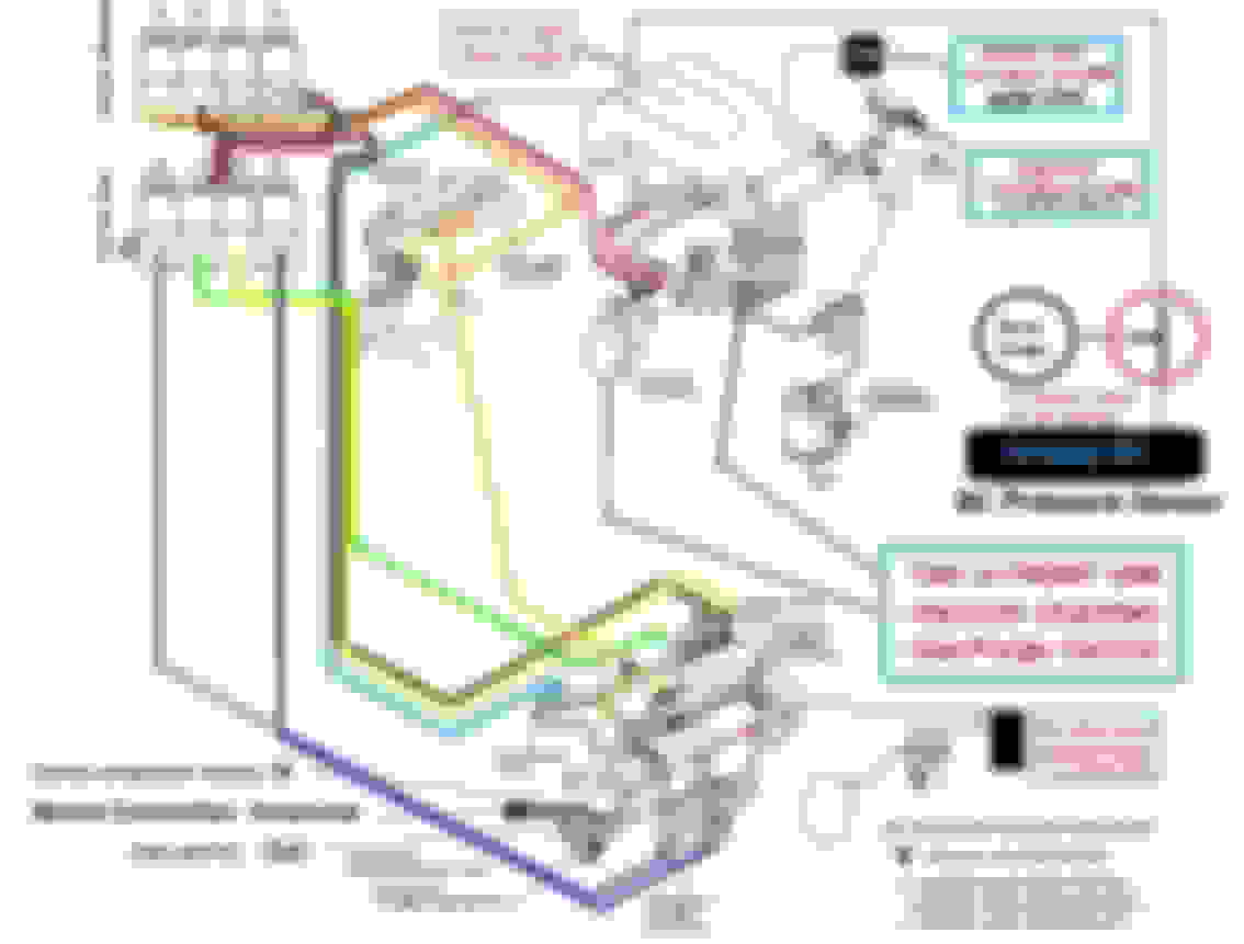
I am doing a simplified sequential setup and following the attached diagram. Could someone confirm where the line with the arrow connects to?
According to other simplified diagrams this line goes to the Pressure Chamber but this diagram has that Pressure Chamber line directly connected to the UIM.
Should this line in question connect to the rear (turbo side) of the UIM, opposite of the Pressure Chamber line?
BNR sequential Stage 1 in 99 twins
AzEKnightz custom solenoid kit
No OMP
Modified separate turbo outlet pipes (no y-pipe)
Oil catch can
Boost Controller
FPR
Newer Stock UIM with only 2 ports on the back for hoses (no emission under it)
Xcessive LIM
I am still building it but this are the silicons hoses I'm using for my set-up.
So while I'm waiting for new hardware to arrive for my current projects, here's a little teaser from my cache of manuals. All I did was add the header text for easy identification.
There is reason you couldn't upgrade. It is a tidier install and less prone to problems due to less connections. It's the same thing in different packaging. Obviously it only has the 7 solenoids so if you have egr you'd still need to keep the old one and house it somewhere.
*rolls up sleeves*
I'm going in!
If I take the UIM off, do I need a new gasket between it and the LIM? If so, are these something you can get at the local auto parts store, or is it dealer or online?
Not planning anything major but want to block off the AWS and EGR and do a couple of vacuum lines.
I believe this was have been covered above, but attaching a pic for clarity
The '95 does not have the EGR stuff:
I found this out when puzzling over why mine didn't have the solenoid for EGR. I had the silicone hoses installed years ago and was thinking maybe they did something with this, but no
Also, a number of the hard tubes that connect the hoses (above the solenoid rack) had no hoses connected and they showed no signs of it (shiny areas on the ends where hoses would have been)
I bought the Banzai Racing block off plate kit and was looking at their photos showing where the plates go and doesn't have that area on the LIM
The LIM also has only 3 hoses nipples where the earlier ones have 4
So the '95 is in effect already simplified to some extent
I found the Banzai Racing block off plate locations photos helpful:


 . However, from an engineering perspective, silicone is not compatible with ASTM Reference Fuel A, B, C, or D. And is not compatible with ASTM Oil 2, 3, 4, and 5. Doubters can check this chart. Yes, I know your personal experience with silicone trumps any standard materials engineering reference. My test with plain old Penzoil 30 weight confirmed that the silicone had some deterioration of the silicone bonds in the tubing exposed to hot oil.
 ) buy fluoropolymer elastomer hose.
 RX-7 Vacuum Diagram 96-02 by Tom Kinsman, on Flickr