
Under car swirl pot/surge tank setups


Thread Starter
Senior Member
Joined: Nov 2007
Posts: 251
Likes: 0
From: Warwickshire, UK
Under car swirl pot/surge tank setups
My car is a street/light track car with full interior, so I don't want to run a swirl pot inside the car. I'm also not a big fan of fuel systems inside the car unless they have to be, so I want to run a swirl pot externally.
Obvious places are bolted to the rear subframe, or where the charcoal canister was. Anywhere else I've missed? No room for it inside the bay.
So, anyone got any piccies of similar setups? I'm looking at using something like this: http://cgi.ebay.co.uk/Race-Rally-Per...item2ea6da2d87
Freom looking at Damien's thrad, it's a similar volume.
Will be fed using a Walbro as a lift pump, and an 044 on the high pressure side.
Any piccies would be greatly appreciated
Ta
Si


Thread Starter
Senior Member
Joined: Nov 2007
Posts: 251
Likes: 0
From: Warwickshire, UK
Thanks, but it would probably work out much cheaper for me to get one from here in the UK 
I don't want to use AN, just normal fuel hose - AN is an expense and a liability I don't think I need in this setup
Everything else firewall forward is AN, but I see no need for it here (In fact, I wish I'd gone startlite in the bay now :o )
I don't want to use AN, just normal fuel hose - AN is an expense and a liability I don't think I need in this setup
Everything else firewall forward is AN, but I see no need for it here
(In fact, I wish I'd gone startlite in the bay now :o )
im very confused why you wouldnt think it would be a good idea after the firewall...but either way the offer still stands!
ill also ship internationally playing with fuel is never safe. so please use cation when doing fuel systems have pics of your build so far?

ill also ship internationally
playing with fuel is never safe. so please use cation when doing fuel systems have pics of your build so far?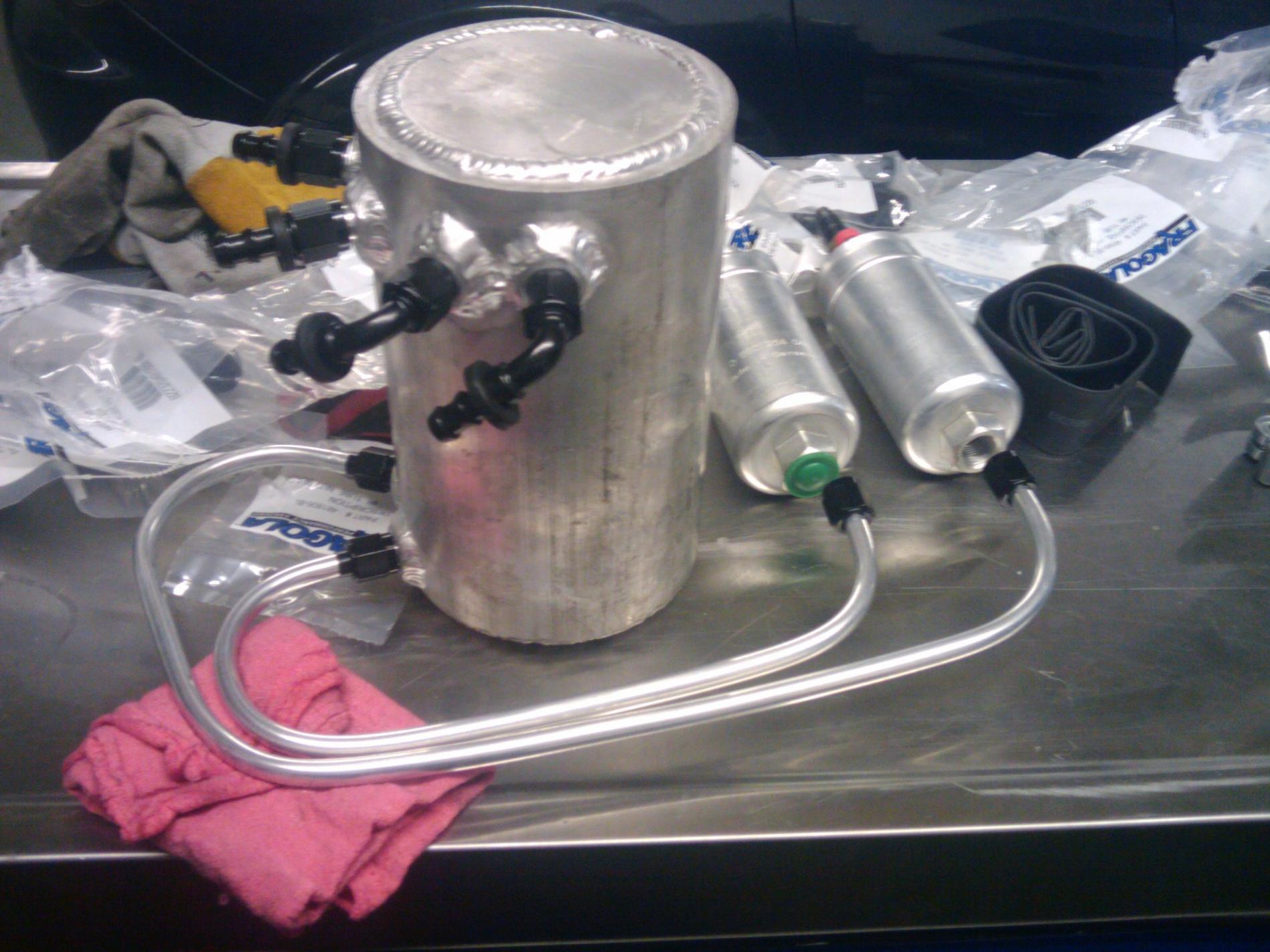
Thread Starter
Senior Member
Joined: Nov 2007
Posts: 251
Likes: 0
From: Warwickshire, UK
I've got plenty of pics, but they're on other forums.
What do you mean 'good idea after the firewall'? I mean as in in the bay - I'm running from the stock hard lines into AN lines in the bay, but I guess that's kinda irrelevant here
Don't worry, I'm being very meticulous in the build, and very very careful - I'm not meddling with stuff that is out of my depth - when it gets to that level I pass it to someone who knows what they are doing!
I'm just trying to see how people have physically positioned stuff under the car at the rear, as all the piccies I find seem to be of boot mounted systems, which I really don't want
boot mounted i think should be avoided unless you enclose it in a box to minimize a fuel fire, there. ill check tomorrow and see if i can fit a tank under the car, if i can ill make one and take some pics for you
and i meant if you have an fittings in the front, why not match with the rear. you will really get much better fuel flow if you were to ditch the oem hardlines and run a -6 return and feed...doesnt cost much either
and i meant if you have an fittings in the front, why not match with the rear. you will really get much better fuel flow if you were to ditch the oem hardlines and run a -6 return and feed...doesnt cost much either
Thread Starter
Senior Member
Joined: Nov 2007
Posts: 251
Likes: 0
From: Warwickshire, UK
I know people definitely do fit tanks under car - bolted to subframes etc - there's also a company here in the UK that does one that goes where the CC goes, but it's nearly 4 times the price of the one I linked to, which I think would do the job very well.
The problem is not many people seem to run a swirl setup outside the car. I know it's more than possible, it's just finding inspiration that's proving tricky! I guess I may have to just see what I can make fit
Trying to avoid replacing the lines as
a) it's an expense I don't need
b) I think it's overkill for my setup ( Divided T4 GT35r, probably pushing circa 1.2 bar. I don't plan on going any higher)
c) I try to use hard line wherever I can, as I personally think it's a neater solution. Hell, I'd hardline everthing if i could
Trending Topics
let me see what i can whip up i sell them for �86 or $130 shipped, ill do international no extra
ill try and get something that fits in nice, how big did you want it? capacity wise that is...
i sell them for �86 or $130 shipped, ill do international no extra ill try and get something that fits in nice, how big did you want it? capacity wise that is...


This is what you want:
https://www.rx7club.com/vendor-classifieds-276/group-buy-fuel-anti-surge-system-fd-877845/
No need for a surge tank with that setup. Track proven. Search for results and other threads on that.
https://www.rx7club.com/vendor-classifieds-276/group-buy-fuel-anti-surge-system-fd-877845/
No need for a surge tank with that setup. Track proven. Search for results and other threads on that.
Thread Starter
Senior Member
Joined: Nov 2007
Posts: 251
Likes: 0
From: Warwickshire, UK
This is what you want:
https://www.rx7club.com/showthread.php?t=877845
No need for a surge tank with that setup. Track proven. Search for results and other threads on that.
https://www.rx7club.com/showthread.php?t=877845
No need for a surge tank with that setup. Track proven. Search for results and other threads on that.
Everything else on this project I've gone for solutions that I'm familiar with - swirl pot is the way I want to go here - although I'm sure the above does an equally good job. I've got all of the parts I need except the pot, so I may as well do it this way.
Gurew - very intersted to see what you can come up with dude - if you can do it for that price and it's bolt in, you'd have yourself a sale. In fact, I may be able to ge ta few more people intersted over here if that's any use?
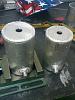
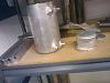
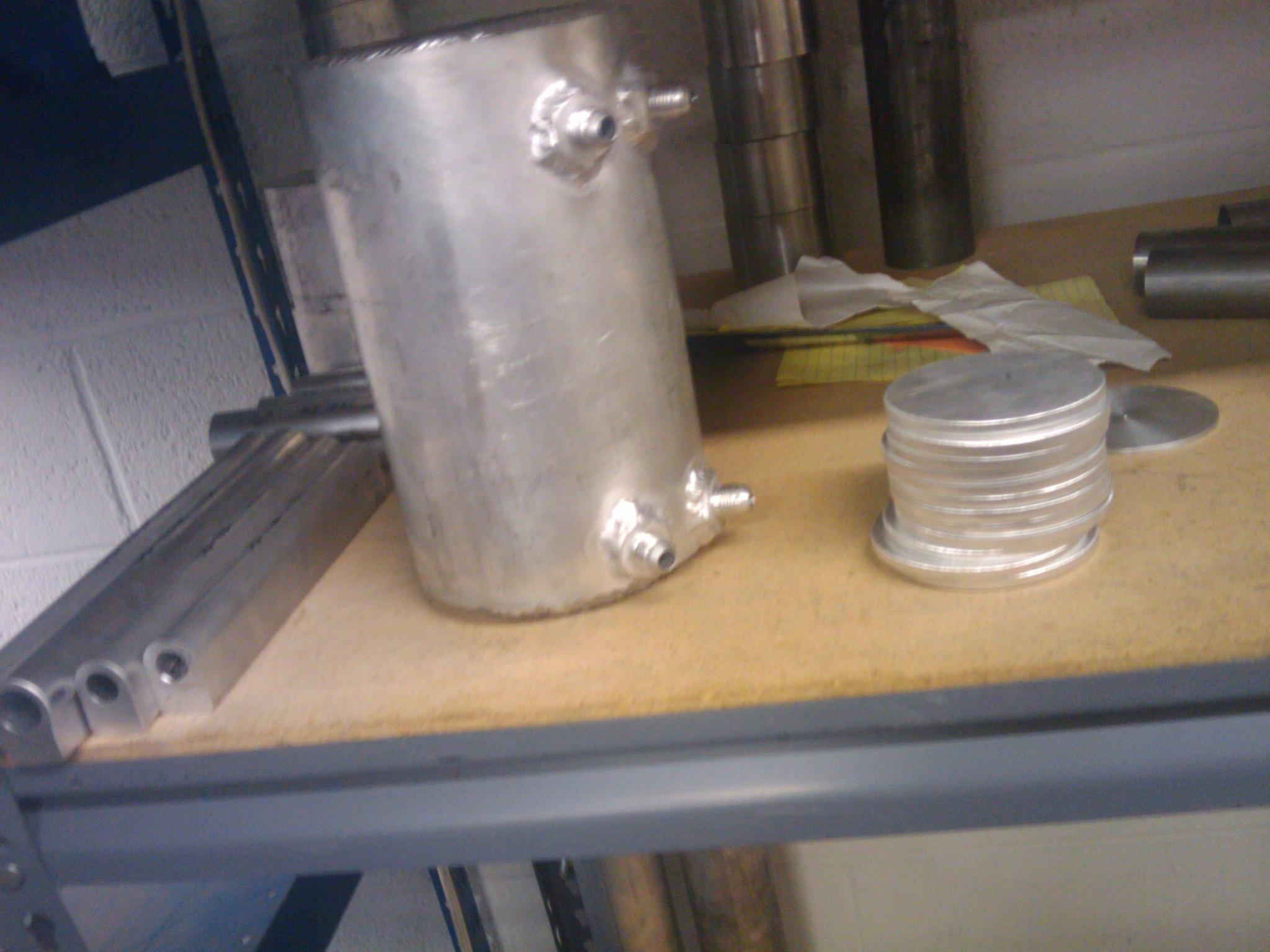
well im on track, should be done wed. ready for ship...but you can get the idea from this picture
pricing was right about where i quoted it so i guess that means im getting better at giving quotes $132 shipped international which is around the $100 mark for the tank itself
fuel in from tank
fuel out to external pump
fuel return from rails
fuel return to tank
those are the ports

pricing was right about where i quoted it so i guess that means im getting better at giving quotes
$132 shipped international which is around the $100 mark for the tank itselffuel in from tank
fuel out to external pump
fuel return from rails
fuel return to tank
those are the ports
Thread Starter
Senior Member
Joined: Nov 2007
Posts: 251
Likes: 0
From: Warwickshire, UK
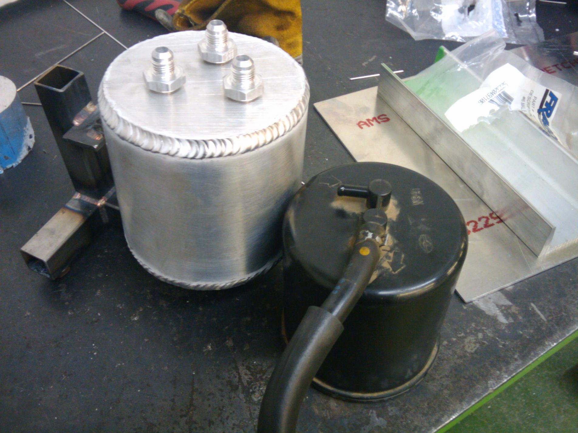
Cool Looking good. Nice welds.
Where are you putting the outlets out of interest? It's quite tight for space at the top IIRC?Are you just doing the tank return on the top?
Feed to primary on the underside or bottom of the side?
And are you running the fittings in at an angle to create the 'swirl'?
Looking good. Nice welds. Where are you putting the outlets out of interest? It's quite tight for space at the top IIRC?Are you just doing the tank return on the top?
Feed to primary on the underside or bottom of the side?
And are you running the fittings in at an angle to create the 'swirl'?
the tank mounts a bit lower than oem but it around the same size, just enough room for the 90degree fittings on top. feed to the primary rail is on the bottom of the pot
no fittings at an angle for swirl, there really is no need based on my experiences.
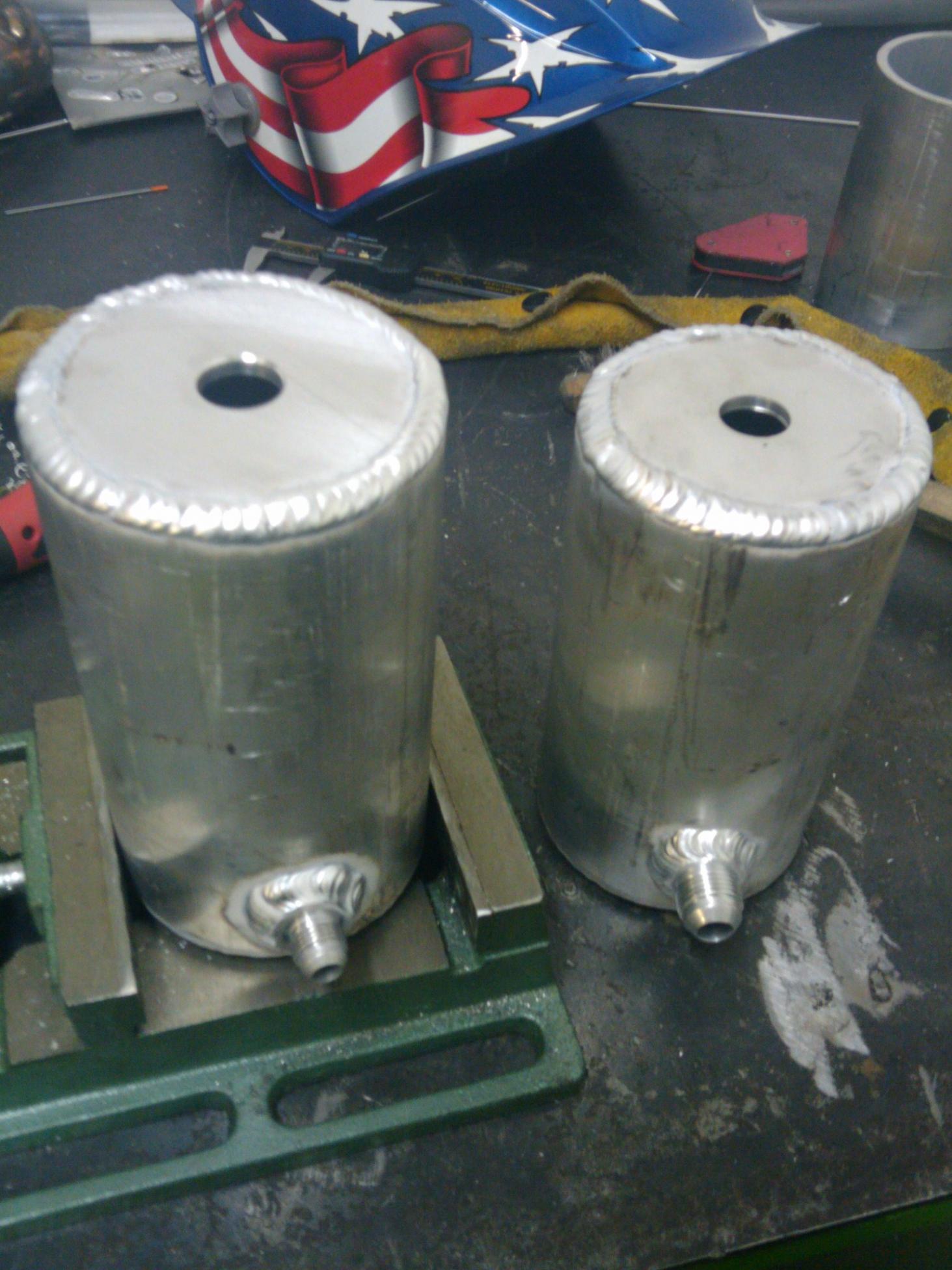
i have 5 tanks in stock ready to be shipped. the tops are waterjet cut and -6 male fittings welded on.
let me know when you want me to ship it out
a little specs for clarification
5" OD 6061-t6 container with .25" wall thickness
.25" thick cap plates waterjet cut, there was a .145"/.25" area for weld, so plenty of penetration and weld area
price is $132 shipped anywhere the united states postal service will ship to.
-6 AN weld on fittings, 3 top (tank feed, rail return, tank return), 1 bottom (primary rail feed) (compatible with JIC fittings in non aerospace use)
finish is brushed aluminum
no fittings at an angle for swirl, there really is no need based on my experiences.
i have 5 tanks in stock ready to be shipped. the tops are waterjet cut and -6 male fittings welded on.
let me know when you want me to ship it out
a little specs for clarification
5" OD 6061-t6 container with .25" wall thickness
.25" thick cap plates waterjet cut, there was a .145"/.25" area for weld, so plenty of penetration and weld area
price is $132 shipped anywhere the united states postal service will ship to.

-6 AN weld on fittings, 3 top (tank feed, rail return, tank return), 1 bottom (primary rail feed) (compatible with JIC fittings in non aerospace use)
finish is brushed aluminum
Senior Member
Joined: Nov 2007
Posts: 343
Likes: 0
From: Australia
do you make these out of aluminium hollow bar? if so, where do you get it from? also could you make one of these but with -8AN fittings and if so, how much? SiH i'll pm you for fitment pics shortly.


Senior Member
Joined: Jun 2008
Posts: 424
Likes: 0
From: Summerfield,FL
Ditto that question. Never have seen pics of a surge tank installed under an fc but am wanting to do so in the near future. Pics please. If the lines go in/out at the top, does that get mounted upside down?....this confuses me a lot because it appears that these are always designed to he used in the hatch, and i want to avoid that. Thanks.
Hi Guys,
I just completed this recently on my track FD and thought I'd post here for people.
Did a bit of a DIY write up including a pump rewire. I have a PDF guide too, but forum won't let me attach it as it's over the 100kb limit.
DIY: Undercar Surge Tank / Swirl Pot & External Fuel Pump Setup
I struggled to find enough information on the options and how best to do this, so decided to write this thread and try to keep everything together. I�ve seen plenty of nice boot mounted setups, but not much info on tidy under car setups.
Couple of notes before we get started:
Please bear in mind that my car is for track use only, so things like increased NVH are not really a priority for me. They may be for you if you�re doing this on a street car, so use common sense. Fuel pumps can be noisy if hard mounted. Obviously with them mounted externally to the fuel tank. I�m also not concerned with roadworthiness, whereas you may well be.
Please remember that all of this is based on my personal experience and opinions. You may or may not agree with my opinions. I�m not a professional and I don�t claim to be, I�m just a guy that likes to tinker in his shed and who�s been around for a while. If you�re at all unsure I suggest you obtain the advice of professionals � or simply don�t begin a project like this. Of course, I�d be happy to advice as necessary and can speak from first hand experience.
As always, I also strongly recommend that you consider your insurance and roadworthiness of your vehicle before performing any modifications. If in doubt, ask a professional.
Be aware of residual fuel pressure & relieve as necessary before removing any lines. You don�t want fuel spraying in your eyes or running down your arms! I recommend when under the car and working on fuel hoses, always wear safety glasses.
I also assume you have a basic knowledge of wiring. If not, get a mate who does to help you with the wiring part. Please use common sense. Fuel & electrical systems need to be right. Take your time!
Ok, on with the details.
Reasons for doing this:
Why would you want to do this? In short, it could save you an engine. Particularly on the track! Ask me how I know lol.
FDs (along with many other cars) have a known issue with starvation at high lateral (sideways) G forces.
FDs are particularly vulnerable on long, sweeping left handers with 1/3 tank or less (as the fuel pump & pickup is on the LH side of the car). When you turn left, the fuel sloshes to the right, away from the pump & pickup! This can result in fuel starvation. Noticeable as a hesitation or cutting out. Usually under boost � the worst time you want to be without fuel!
The OEM fuel pump / pickup sits inside a �bucket� in the tank. This is designed to minimise the fuel sloshing away. Early cars (like my version I) don�t have a �lid� on the bucket. The later cars do. Mazda did try to address the problem. I purchased a Hyperion cover / lid for mine made by RS Engineering. With a lid, the bucket works better against preventing surge � but it doesn�t stop it completely. Especially with � tank or less and if you�re really going fast around corners.
The issue can be addressed by always making sure you have more than �� tank in your car whenever �spirited� driving is to occur. For me, I just got sick of topping the car up all the time and carrying around all that extra weight to prevent surge.
With a proper surge tank setup, the engine will have a virtually uninterruptable supply of fuel, regardless of the cornering or braking/acceleration g forces (not sure about if you�re upside down ha ha). It also allows you to run all the way down to minimum reserves without worrying about a lean out from fuel surge.
Overall budget for this is around $500. But this really depends on the tank, pump, etc you go for. How much you make yourself will also obviously affect the cost.
What You�ll need:
Here�s the majority of what you�ll need:
Surge tank � Make or buy � heaps of different types, shapes & options
About 2-3m of 8mm or 5/16� EFI Fuel hose � note: make sure hose is compatible with the fuel you�re going to run (ie, E85, etc)
Short length (I only used about 125mm) of 12mm � �� EFI Fuel hose
Fuel hose clamps to suit above hoses, approx. 10
External Fuel Pump (w fittings) � I went with a Bosch Motorsports 044 which is rated at 300LPH or 700HP
Mounting bracket for external fuel pump
Aluminium plate about 400mm x 400mm
Various hose clamps (for mounting bracket to rear subframe)
SS bolts & nylock nuts for mounting pump bracket & surge tank
5-10m of 2.9mm, 25amp cable (Red & black)
Inline fuse holder for above wire
Standard 30Amp 12V 85/86 SPST relay, Bosch, Narva or similar
Soldering Iron & solder
Heat shrink
Electrical tape
Various crimp connectors
Cardboard & scissors
Marker pen
Drill
File
Bench with Vice
Hacksaw
Pliers / crimpers
Cutters
Patience
Note: I�ve already upgraded the stock fuel pump to a Walbro unit. If using the stock pump, it�s worth checking to make sure it can flow enough to satisfy the new external unit. However if you plumb up as shown in my diagrams with return back to surge tank, it�s less of a critical issue.
Diagrams
I knocked up a couple of quick reference diagrams in CAD. Kept them black & white for ease of printing.
These show the OEM system and the way the fuel lines are plumbed, versus the new configuration with a surge tank.
Here�s a simplified diagram of the stock fuel system.
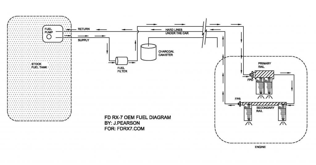
Here�s a diagram showing where to plumb the lines with your new surge tank.
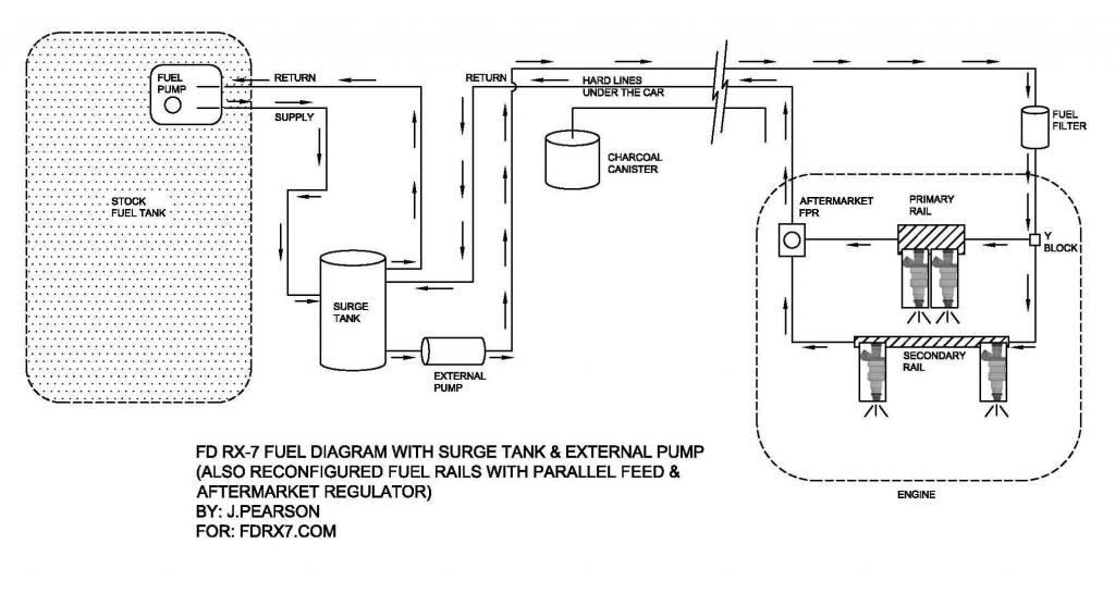
Note: if engine return line is connected to the surge tank as shown here, you don�t need to worry about the lift pump having to outflow the new main pump. Some say that this way can cause the fuel to heat up gradually. If concerned about this, just run a fuel cooler on your return line.
For clarity, I�ve tried to show the hard lines where they are in the car, ie: when standing at the front of the car looking to the rear, the line on the LH outside is the supply (closest to the sill), return is in the middle then charcoal canister on the left (closest to trans tunnel).
Here�s the procedure and how I tackled it.
Step 1 � Decide where the tank will go
You need good access under the rear of the car. Jack up under the diff and support vehicle on jackstands, or put the car up on a hoist. Always be confident that the car can�t go anywhere before climbing under it!
Like I said previously, there� plenty of people who just put a surge tank and fuel pump inside the boot, spare wheel well or similar. This is fine, but for motorsport use, a fire wall is required to prevent fumes from entering the drivers cabin. I also don�t like the idea of the fire hazard. To make a firewall would be messy and ad more weight, so I decided to place all this under the car.
There are basically two main spots available (presuming you�re running the stock tank like me).
1. Behind the rear subframe
2. Where the charcoal canister mounts (LH side, just forward of the LH driveshaft)
I went with option 1. Depending on which option you take, it could affect the size and shape of the surge tank you can use. I thought that option 2 looked a bit tight on space and difficult to access.
The surge tank itself can be any sort of size or shape really. It can be made from aluminium, steel or stainless, doesn�t matter a whole lot. Importantly, it needs to have 4 outlets.
I had a few different size tanks and have decided on using a small cylindrical one. It�s capacity is only about half a litre, but I�m reasonably confident it will do the job for the power levels of my car. Surge is only really likely for a few seconds at a time. There would be plenty of gurus who can some up with flow / time / capacity graphs and theories. I�ve just decided to rock with this one and see how I go. Time will tell. If needed I can swap it out and make a larger one with more capacity for the job.
This one fits easily in the available space. It�s approx. 75mm diameter and 130mm long.
The tank I�m using has 3 x 8mm barbs up the top and 1 x 12mm barb down the bottom for the feed to new external pump.
Step 2 � Mock everything up
Working under the car, asses the available space and hold things up to work out where everything will go. I decided to make a bracket that clamped to the rear subframe and would hold both the surge tank and the 044 fuel pump.
If deciding on a size & shape for a surge tank to be fabricated, I found it helpful to cut a piece of PVC pipe the same diameter as your proposed surge tank. It�s easy to trim to length and hold up in place to work out where mounting tabs, etc need to go.
I removed the LH rear brace to give me more room to reach up and around things.
Note: With my setup, I decided against running an additional filter before the external pump. I�m already running an engine bay mounted filter before the fuel enters the engine. There is a sock filter on the pickup of the in tank pump, which I�ve had out and cleaned. Plus I know for a fact my tank is very clean inside. I also always run 98 fuel. You may decide otherwise. Totally up to you. Just be aware that this may affect the design & shape of your bracket, plus the amount of hose & clamps you need.
Step 3 � Cut mounting bracket & install
So using the tried and tested method of card board & scissors (easy to trim and make quick adjustments to shape, etc), Laying out the pump and tank on the bench then tracing rough shape, I cut out a template to mock up under the subframe.
I then marked out slots for SS hose clamps to attach it to the subframe. 1 vertically and 1 horizontally. I didn�t like the idea of drilling or welding to the stock subframe which is why I decided to clamp it on. You may decide differently. You want to ensure that neither the tank nor the pump is hanging down too low. I made sure that the bracket was up high, keeping everything out of the way.
Once you�re happy with the cardboard template and have checked it fits well to the subframe and will hold the surge tank & fuel pump, transfer the shape to a piece of aluminium plate, something like 3mm (I used alucabond because it�s what I had available)
Cut out with hacksaw / grinder, then clean up all edges with file / sandpaper. Drill holes for mounting bolts and create slots for SS hose clamps.
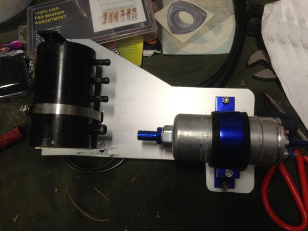
Here�s my bracket, with the pump and tank test fitted:
Then off with tank & pump, and installed bracket to subframe. Note the clamp on design:
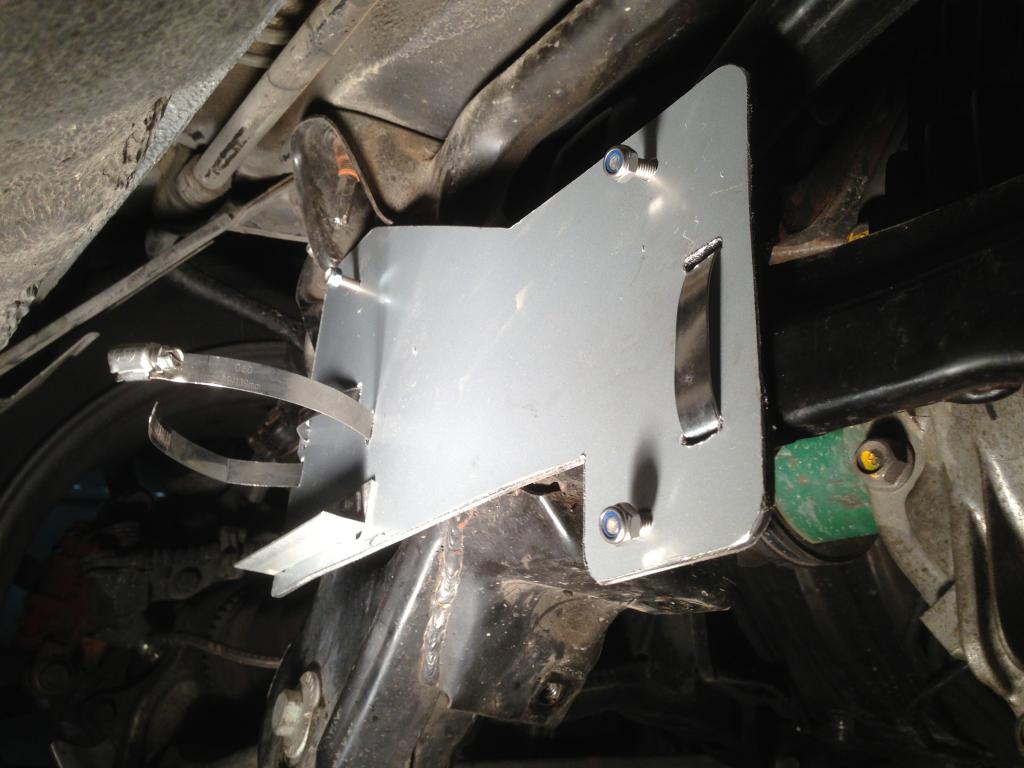
Give it a good wiggle! Mine didn�t move at all and is rock solid with one clamp holding it horizontally, the other vertically. It can�t move!
Step 4 � Mount the tank & pump
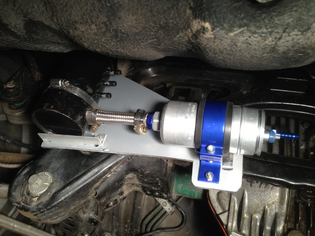
Securely mount the surge tank and fuel pump to the bracket. For the surge tank, I used a tab at the top with a SS bolt & nylock nut, with a hose clamp gripping the bottom of the tank. I also used a small piece of aluminium angle bolted to the mounting bracket to create a lip for the base of the surge tank to sit on. The result is the tank is firmly mounted and can�t go anywhere. Use your common sense and ensure things are very firmly mounted and can�t rattle or work their way loose. For mounting of the fuel pump, I used a 25D bracket made from anodized aluminium (about $20 on eBay) to firmly hold the 044 pump. It has a layer of rubber to grip the pump and prevent too much noise. Again, I used SS bolts and nylock nuts to bolt the pump bracket to my mounting bracket. It�s VERY important that things stay in place. Remember your hot exhaust and spinning drive shafts are in close proximity. If anything comes loose and creates a fuel leak, there could be horrible consequences! Take your time and ensure everything is locked down.
Here�s a pic of the pump & surge tank installed to the bracket I made:
Step 5 � Plumb the lines
Refer to the diagram above and plumb in the rubber hoses. It�s best to have the highest outlet on the surge tank as the return back to the main tank. You can use braided with or without fancy fittings, depending on your taste & budget.
Always make sure the hose type is compatible with the fuel you�re running. I�m just running pump fuel so plain old EFI hose will do just fine. I had a piece of braided 12mm hose so cut a short bit for between the tank and inlet to the pump.
When running the new lines, have a good look at the surrounding structures such as exhaust, driveshafts, etc. Use your head, allow for suspension movement and ensure all new lines are up out of the way of everything that moves or gets hot, both of which could cause you issues if you run the lines carelessly!
A note about clamps. The factory Mazda ones are quite good in their design. I chose to reuse some of them where the lines connect to the tank. If using aftermarket clamps, I recommend these type:
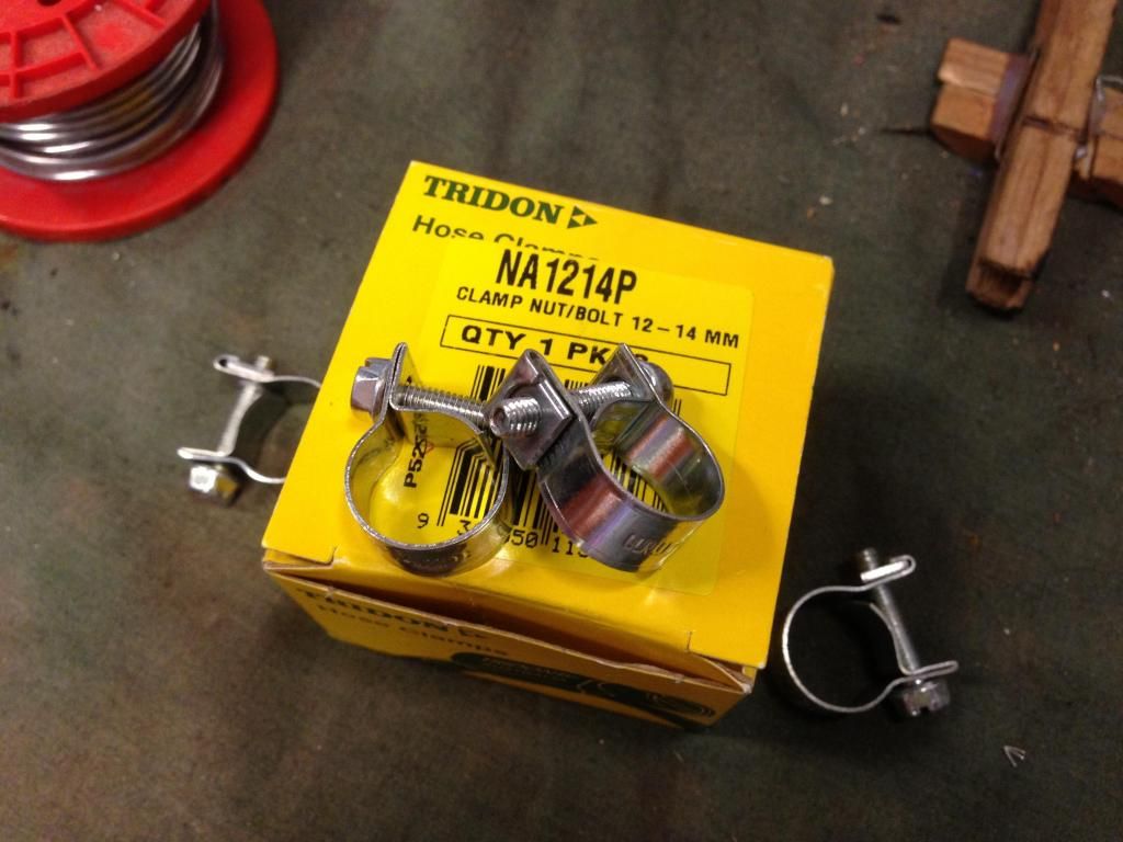
Available in a box of 10. They�re not expensive and do the job nicely. They are specifically designed for fuel lines. IMO don�t use the worm type on rubber hoses as they can cut into the hose as you tighten them. Especially if you do them up stupidly tight!
Face all your clamps so they are easy to get to. I chose to double up clamps on the outlet of the new pump. The clamps need to be firm, but don�t over tighten them.
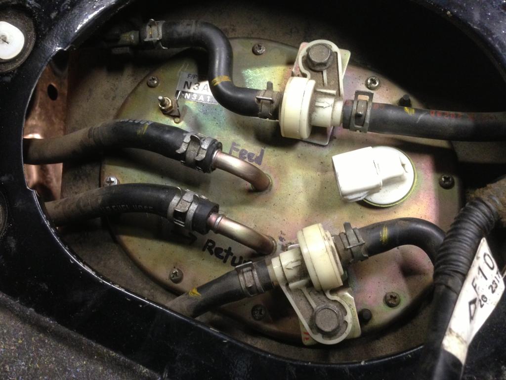
Here�s a pic of the tank to show clearly which is the FEED and which is the RETURN line (see where I've written in black texter)
Step 6 � Wire up the pump
Electrical
As per usual when doing electrical work on a car, take your time! Be neat. Think about the job carefully. Soldering with heat shrink is the best bet. Crimp if you have to, but use proper crimpers and if possible, solder the joints as well. NEVER just twist and tape up things. Don�t use those horrible piggyback snap connectors either!
It�s always good practice to remove the negative terminal on your battery before mucking around with wiring.
The stock FD in tank fuel pump is controlled by the ECU with various relays, plugs and a resistor.
There is an inherent issue with the cars not getting full 12V to the fuel pump. The stock system has a resistor (under the brake booster) that drops the voltage to about 9V under idle to help fuel economy & presumably, prolong the life of the fuel pump. There is a bypass when full battery voltage is required to the pump.
Why rewire the fuel pump?
- Even on a car with a new alternator, new battery, new battery terminals, and clean electrical connections, it has been reported that voltages low as 10v to the fuel pump can been seen with a load on the system (lights on, stereo, heater on, etc.)
- The fuel pump should, under boost, be seeing at LEAST 12v. Reduction in voltage can lead to a reduction in fuel flow, creating dangerously lean AFRs and worse still, engine failure.
Since you�re introducing a new, external fuel pump, I figure now is as good a time as any to tackle this issue and ensure your new pump (& in tank pump) are getting full battery voltage.
There are a few theories on why the fuel pump doesn�t get full 12V with the factory wiring. Some say the amount of connections, some sad bad grounds, some say the length & quality of the cable itself and others say a combination of all of these are the cause.
I decided to use the factory wiring to control a relay which will run both pumps, but run my own new fused power supply directly from the battery.
So here�s an electrical diagram on how I connected things:
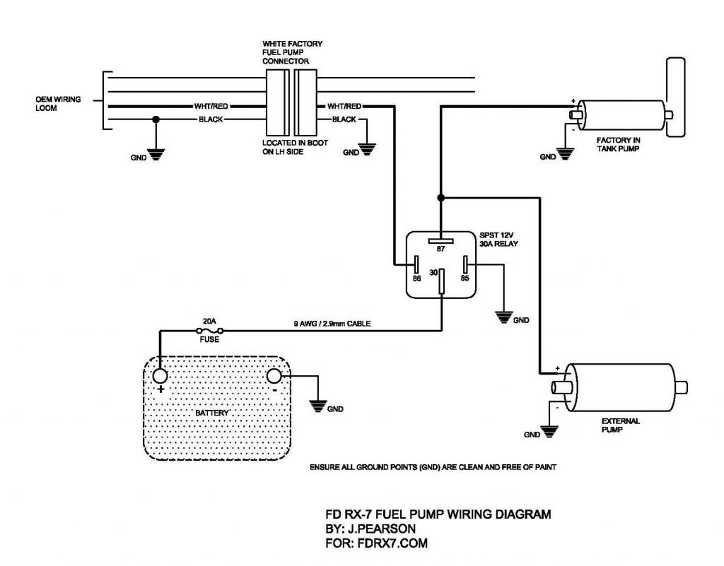
All ground points should be clean, free of paint and firmly bolted. I like to use serrated washers to really dig into the metal and get a good contact point.
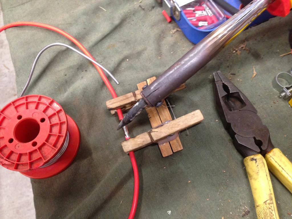
Just a note on soldering wires. I recommend you make yourself up one of these simple gadgets. Made from 3 wooden clothes pegs and a bit of hot glue, it makes holding wires in position whilst you solder MUCH easier, resulting in a better solder job! I use mine all the time and love it! J
Cutting the red/white wire - stock 12V pump power supply that will now simply be used to operate new relay.
Once you�ve run all your wires and made all your terminations as per the diagram, soldered things, applied heat shrink and neatly wrapped everything up, you�re nearly ready to test.
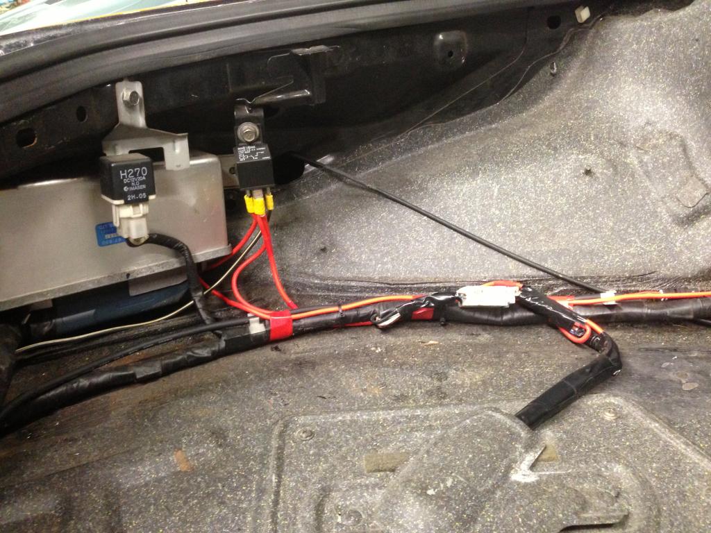
Plug in the stock wiring back to the pump (don�t forget the earth terminal).
Here�s a pic of my relay, all wired up and ready to go:
Step 7 � Pressurize system & check for leaks
Before you start the engine, I recommend just turning the ignition on a few times to prime the system and run your pumps for a little bit. Then, thoroughly check for leaks and address as necessary.
If no leaks are evident, replace your negative battery terminal, ensure the car is in neutral, then start up the engine. I recommend running it for a short while before shutting it off, getting underneath again and having a really good look once more with a torch to make sure there aren�t any leaks of any kind and that your hoses are properly secured.
After that, simply jack up, remove your jack stands and lower the car down carefully. Once on the ground, take a peep under the back again and admire your handiwork. If you�ve done a good job, you shouldn�t be able to tell very easily that you were even there! Certainly there shouldn�t be anything hanging down too low.
Don�t forget to replace the fuel access lid with its 4 phillips screws!
Here�s a couple more pics of my finished setup, all ready to go:
End of write up.
I hope this information is helpful. I know I would have really appreciated a thread like this when I was organizing myself to get a setup in the car.
I just completed this recently on my track FD and thought I'd post here for people.
Did a bit of a DIY write up including a pump rewire. I have a PDF guide too, but forum won't let me attach it as it's over the 100kb limit.
DIY: Undercar Surge Tank / Swirl Pot & External Fuel Pump Setup
I struggled to find enough information on the options and how best to do this, so decided to write this thread and try to keep everything together. I�ve seen plenty of nice boot mounted setups, but not much info on tidy under car setups.
Couple of notes before we get started:
Please bear in mind that my car is for track use only, so things like increased NVH are not really a priority for me. They may be for you if you�re doing this on a street car, so use common sense. Fuel pumps can be noisy if hard mounted. Obviously with them mounted externally to the fuel tank. I�m also not concerned with roadworthiness, whereas you may well be.
Please remember that all of this is based on my personal experience and opinions. You may or may not agree with my opinions. I�m not a professional and I don�t claim to be, I�m just a guy that likes to tinker in his shed and who�s been around for a while. If you�re at all unsure I suggest you obtain the advice of professionals � or simply don�t begin a project like this. Of course, I�d be happy to advice as necessary and can speak from first hand experience.
As always, I also strongly recommend that you consider your insurance and roadworthiness of your vehicle before performing any modifications. If in doubt, ask a professional.
Be aware of residual fuel pressure & relieve as necessary before removing any lines. You don�t want fuel spraying in your eyes or running down your arms! I recommend when under the car and working on fuel hoses, always wear safety glasses.
I also assume you have a basic knowledge of wiring. If not, get a mate who does to help you with the wiring part. Please use common sense. Fuel & electrical systems need to be right. Take your time!
Ok, on with the details.
Reasons for doing this:
Why would you want to do this? In short, it could save you an engine. Particularly on the track! Ask me how I know lol.
FDs (along with many other cars) have a known issue with starvation at high lateral (sideways) G forces.
FDs are particularly vulnerable on long, sweeping left handers with 1/3 tank or less (as the fuel pump & pickup is on the LH side of the car). When you turn left, the fuel sloshes to the right, away from the pump & pickup! This can result in fuel starvation. Noticeable as a hesitation or cutting out. Usually under boost � the worst time you want to be without fuel!
The OEM fuel pump / pickup sits inside a �bucket� in the tank. This is designed to minimise the fuel sloshing away. Early cars (like my version I) don�t have a �lid� on the bucket. The later cars do. Mazda did try to address the problem. I purchased a Hyperion cover / lid for mine made by RS Engineering. With a lid, the bucket works better against preventing surge � but it doesn�t stop it completely. Especially with � tank or less and if you�re really going fast around corners.
The issue can be addressed by always making sure you have more than �� tank in your car whenever �spirited� driving is to occur. For me, I just got sick of topping the car up all the time and carrying around all that extra weight to prevent surge.
With a proper surge tank setup, the engine will have a virtually uninterruptable supply of fuel, regardless of the cornering or braking/acceleration g forces (not sure about if you�re upside down ha ha). It also allows you to run all the way down to minimum reserves without worrying about a lean out from fuel surge.
Overall budget for this is around $500. But this really depends on the tank, pump, etc you go for. How much you make yourself will also obviously affect the cost.
What You�ll need:
Here�s the majority of what you�ll need:
Surge tank � Make or buy � heaps of different types, shapes & options
About 2-3m of 8mm or 5/16� EFI Fuel hose � note: make sure hose is compatible with the fuel you�re going to run (ie, E85, etc)
Short length (I only used about 125mm) of 12mm � �� EFI Fuel hose
Fuel hose clamps to suit above hoses, approx. 10
External Fuel Pump (w fittings) � I went with a Bosch Motorsports 044 which is rated at 300LPH or 700HP
Mounting bracket for external fuel pump
Aluminium plate about 400mm x 400mm
Various hose clamps (for mounting bracket to rear subframe)
SS bolts & nylock nuts for mounting pump bracket & surge tank
5-10m of 2.9mm, 25amp cable (Red & black)
Inline fuse holder for above wire
Standard 30Amp 12V 85/86 SPST relay, Bosch, Narva or similar
Soldering Iron & solder
Heat shrink
Electrical tape
Various crimp connectors
Cardboard & scissors
Marker pen
Drill
File
Bench with Vice
Hacksaw
Pliers / crimpers
Cutters
Patience
Note: I�ve already upgraded the stock fuel pump to a Walbro unit. If using the stock pump, it�s worth checking to make sure it can flow enough to satisfy the new external unit. However if you plumb up as shown in my diagrams with return back to surge tank, it�s less of a critical issue.
Diagrams
I knocked up a couple of quick reference diagrams in CAD. Kept them black & white for ease of printing.
These show the OEM system and the way the fuel lines are plumbed, versus the new configuration with a surge tank.
Here�s a simplified diagram of the stock fuel system.

Here�s a diagram showing where to plumb the lines with your new surge tank.

Note: if engine return line is connected to the surge tank as shown here, you don�t need to worry about the lift pump having to outflow the new main pump. Some say that this way can cause the fuel to heat up gradually. If concerned about this, just run a fuel cooler on your return line.
For clarity, I�ve tried to show the hard lines where they are in the car, ie: when standing at the front of the car looking to the rear, the line on the LH outside is the supply (closest to the sill), return is in the middle then charcoal canister on the left (closest to trans tunnel).
Here�s the procedure and how I tackled it.
Step 1 � Decide where the tank will go
You need good access under the rear of the car. Jack up under the diff and support vehicle on jackstands, or put the car up on a hoist. Always be confident that the car can�t go anywhere before climbing under it!
Like I said previously, there� plenty of people who just put a surge tank and fuel pump inside the boot, spare wheel well or similar. This is fine, but for motorsport use, a fire wall is required to prevent fumes from entering the drivers cabin. I also don�t like the idea of the fire hazard. To make a firewall would be messy and ad more weight, so I decided to place all this under the car.
There are basically two main spots available (presuming you�re running the stock tank like me).
1. Behind the rear subframe
2. Where the charcoal canister mounts (LH side, just forward of the LH driveshaft)
I went with option 1. Depending on which option you take, it could affect the size and shape of the surge tank you can use. I thought that option 2 looked a bit tight on space and difficult to access.
The surge tank itself can be any sort of size or shape really. It can be made from aluminium, steel or stainless, doesn�t matter a whole lot. Importantly, it needs to have 4 outlets.
I had a few different size tanks and have decided on using a small cylindrical one. It�s capacity is only about half a litre, but I�m reasonably confident it will do the job for the power levels of my car. Surge is only really likely for a few seconds at a time. There would be plenty of gurus who can some up with flow / time / capacity graphs and theories. I�ve just decided to rock with this one and see how I go. Time will tell. If needed I can swap it out and make a larger one with more capacity for the job.
This one fits easily in the available space. It�s approx. 75mm diameter and 130mm long.
The tank I�m using has 3 x 8mm barbs up the top and 1 x 12mm barb down the bottom for the feed to new external pump.
Step 2 � Mock everything up
Working under the car, asses the available space and hold things up to work out where everything will go. I decided to make a bracket that clamped to the rear subframe and would hold both the surge tank and the 044 fuel pump.
If deciding on a size & shape for a surge tank to be fabricated, I found it helpful to cut a piece of PVC pipe the same diameter as your proposed surge tank. It�s easy to trim to length and hold up in place to work out where mounting tabs, etc need to go.
I removed the LH rear brace to give me more room to reach up and around things.
Note: With my setup, I decided against running an additional filter before the external pump. I�m already running an engine bay mounted filter before the fuel enters the engine. There is a sock filter on the pickup of the in tank pump, which I�ve had out and cleaned. Plus I know for a fact my tank is very clean inside. I also always run 98 fuel. You may decide otherwise. Totally up to you. Just be aware that this may affect the design & shape of your bracket, plus the amount of hose & clamps you need.
Step 3 � Cut mounting bracket & install
So using the tried and tested method of card board & scissors (easy to trim and make quick adjustments to shape, etc), Laying out the pump and tank on the bench then tracing rough shape, I cut out a template to mock up under the subframe.
I then marked out slots for SS hose clamps to attach it to the subframe. 1 vertically and 1 horizontally. I didn�t like the idea of drilling or welding to the stock subframe which is why I decided to clamp it on. You may decide differently. You want to ensure that neither the tank nor the pump is hanging down too low. I made sure that the bracket was up high, keeping everything out of the way.
Once you�re happy with the cardboard template and have checked it fits well to the subframe and will hold the surge tank & fuel pump, transfer the shape to a piece of aluminium plate, something like 3mm (I used alucabond because it�s what I had available)
Cut out with hacksaw / grinder, then clean up all edges with file / sandpaper. Drill holes for mounting bolts and create slots for SS hose clamps.
Here�s my bracket, with the pump and tank test fitted:

Then off with tank & pump, and installed bracket to subframe. Note the clamp on design:

Give it a good wiggle! Mine didn�t move at all and is rock solid with one clamp holding it horizontally, the other vertically. It can�t move!
Step 4 � Mount the tank & pump
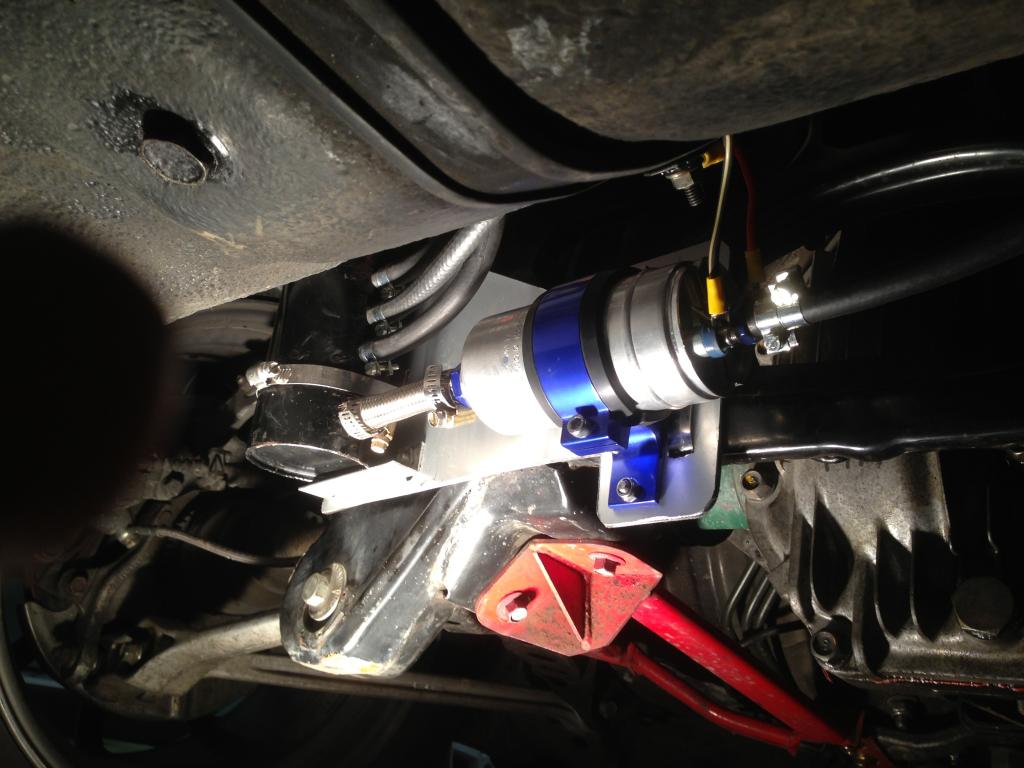
Securely mount the surge tank and fuel pump to the bracket. For the surge tank, I used a tab at the top with a SS bolt & nylock nut, with a hose clamp gripping the bottom of the tank. I also used a small piece of aluminium angle bolted to the mounting bracket to create a lip for the base of the surge tank to sit on. The result is the tank is firmly mounted and can�t go anywhere. Use your common sense and ensure things are very firmly mounted and can�t rattle or work their way loose. For mounting of the fuel pump, I used a 25D bracket made from anodized aluminium (about $20 on eBay) to firmly hold the 044 pump. It has a layer of rubber to grip the pump and prevent too much noise. Again, I used SS bolts and nylock nuts to bolt the pump bracket to my mounting bracket. It�s VERY important that things stay in place. Remember your hot exhaust and spinning drive shafts are in close proximity. If anything comes loose and creates a fuel leak, there could be horrible consequences! Take your time and ensure everything is locked down.
Here�s a pic of the pump & surge tank installed to the bracket I made:

Step 5 � Plumb the lines
Refer to the diagram above and plumb in the rubber hoses. It�s best to have the highest outlet on the surge tank as the return back to the main tank. You can use braided with or without fancy fittings, depending on your taste & budget.
Always make sure the hose type is compatible with the fuel you�re running. I�m just running pump fuel so plain old EFI hose will do just fine. I had a piece of braided 12mm hose so cut a short bit for between the tank and inlet to the pump.
When running the new lines, have a good look at the surrounding structures such as exhaust, driveshafts, etc. Use your head, allow for suspension movement and ensure all new lines are up out of the way of everything that moves or gets hot, both of which could cause you issues if you run the lines carelessly!
A note about clamps. The factory Mazda ones are quite good in their design. I chose to reuse some of them where the lines connect to the tank. If using aftermarket clamps, I recommend these type:

Available in a box of 10. They�re not expensive and do the job nicely. They are specifically designed for fuel lines. IMO don�t use the worm type on rubber hoses as they can cut into the hose as you tighten them. Especially if you do them up stupidly tight!
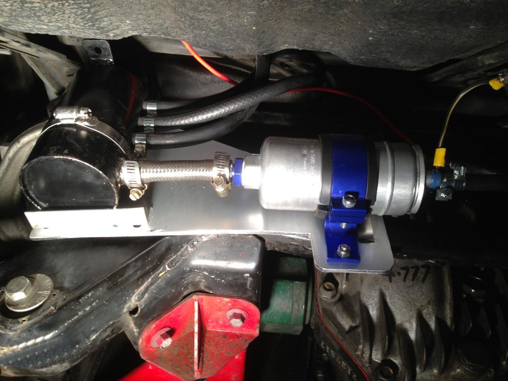
Face all your clamps so they are easy to get to. I chose to double up clamps on the outlet of the new pump. The clamps need to be firm, but don�t over tighten them.
Here�s a pic of the tank to show clearly which is the FEED and which is the RETURN line (see where I've written in black texter)

Step 6 � Wire up the pump
Electrical
As per usual when doing electrical work on a car, take your time! Be neat. Think about the job carefully. Soldering with heat shrink is the best bet. Crimp if you have to, but use proper crimpers and if possible, solder the joints as well. NEVER just twist and tape up things. Don�t use those horrible piggyback snap connectors either!
It�s always good practice to remove the negative terminal on your battery before mucking around with wiring.
The stock FD in tank fuel pump is controlled by the ECU with various relays, plugs and a resistor.
There is an inherent issue with the cars not getting full 12V to the fuel pump. The stock system has a resistor (under the brake booster) that drops the voltage to about 9V under idle to help fuel economy & presumably, prolong the life of the fuel pump. There is a bypass when full battery voltage is required to the pump.
Why rewire the fuel pump?
- Even on a car with a new alternator, new battery, new battery terminals, and clean electrical connections, it has been reported that voltages low as 10v to the fuel pump can been seen with a load on the system (lights on, stereo, heater on, etc.)
- The fuel pump should, under boost, be seeing at LEAST 12v. Reduction in voltage can lead to a reduction in fuel flow, creating dangerously lean AFRs and worse still, engine failure.
Since you�re introducing a new, external fuel pump, I figure now is as good a time as any to tackle this issue and ensure your new pump (& in tank pump) are getting full battery voltage.
There are a few theories on why the fuel pump doesn�t get full 12V with the factory wiring. Some say the amount of connections, some sad bad grounds, some say the length & quality of the cable itself and others say a combination of all of these are the cause.
I decided to use the factory wiring to control a relay which will run both pumps, but run my own new fused power supply directly from the battery.
So here�s an electrical diagram on how I connected things:

All ground points should be clean, free of paint and firmly bolted. I like to use serrated washers to really dig into the metal and get a good contact point.
Just a note on soldering wires. I recommend you make yourself up one of these simple gadgets. Made from 3 wooden clothes pegs and a bit of hot glue, it makes holding wires in position whilst you solder MUCH easier, resulting in a better solder job! I use mine all the time and love it! J

Cutting the red/white wire - stock 12V pump power supply that will now simply be used to operate new relay.
Once you�ve run all your wires and made all your terminations as per the diagram, soldered things, applied heat shrink and neatly wrapped everything up, you�re nearly ready to test.
Plug in the stock wiring back to the pump (don�t forget the earth terminal).
Here�s a pic of my relay, all wired up and ready to go:

Step 7 � Pressurize system & check for leaks
Before you start the engine, I recommend just turning the ignition on a few times to prime the system and run your pumps for a little bit. Then, thoroughly check for leaks and address as necessary.
If no leaks are evident, replace your negative battery terminal, ensure the car is in neutral, then start up the engine. I recommend running it for a short while before shutting it off, getting underneath again and having a really good look once more with a torch to make sure there aren�t any leaks of any kind and that your hoses are properly secured.
After that, simply jack up, remove your jack stands and lower the car down carefully. Once on the ground, take a peep under the back again and admire your handiwork. If you�ve done a good job, you shouldn�t be able to tell very easily that you were even there! Certainly there shouldn�t be anything hanging down too low.
Don�t forget to replace the fuel access lid with its 4 phillips screws!
Here�s a couple more pics of my finished setup, all ready to go:


End of write up.
I hope this information is helpful. I know I would have really appreciated a thread like this when I was organizing myself to get a setup in the car.
Junior Member
Joined: Nov 2008
Posts: 30
Likes: 0
From: Riverside, CA
Wow that was a great, informative write up! I am currently in the process of wiring my fuel pump and also will install my surge tank in my fc. Although for an FD, the information provided was very direct and detailed. Thank you sir.

Thread
Thread Starter
Forum
Replies
Last Post
immanuel__7
2nd Generation Specific (1986-1992)
89
Sep 5, 2015 10:23 AM
KAL797
Test Area 51
0
Aug 11, 2015 03:47 PM