
Throttle Body Adjustments

Throttle Body Adjustments
I am getting ready to set up a new ECU (PowerFC) and want to make sure everything is adjusted properly on the throttle body. I need some help interpreting some of this stuff from the FSM.
1. On the fast idle cam (first picture) does it look like I have the correct mark aligned properly?
2. Also the round stop is just touching the cam. Is that OK? Not sure where to set that stop.
3. The next picture just shows the wax rod and the screw which sets the cam but there is also a small allen head screw that looks like a stop. The screw at the wax rod sets the cam but I probably shouldn't touch the allen screw, right?
4. The third picture shows the throttle (idle speed) screw on the other side of the throttle body. This screw (#3) and screw #4 and screw #1 all seem to work together to open and close the primary throttle plate.
So can someone help me understand how to adjust all of these screws. I think I am close on the fast idle cam, the screw which controls the stop at the cam (#4) is set so the stop just touches the cam, and #3 (the idle speed) is barely touching it's stop. So basically the primary throttle plates are very nearly closed.
And where should the air bleed screw be? I have heard that out a half turn or so is about right. Is that also enough aire for a half bridge port?
So how does the fast idle work? I would think that when the engine is cold and the wax rod is retracted the throttle plates would be open for a fast idle. I wanted to wait to put this back on until I (hopefully) get some answers.
Any help on this would be appreciated.
Thanks,
Jeff


No I don't yet. I plan on subscribing to Chuck's service but was going to wait until I bought the Datalogit. Maybe they would be beneficial now even with just a Commander. I have heard they are an excellent resource.
But why is the FSM so lacking in this area?
But why is the FSM so lacking in this area?
The FSM covers a lot of this, you just have to know where to look. The 2nd gen turbo FSM has some really good diagrams as well, that TB is the same basic design. I don't have mine on this computer so I can't give you page numbers right now. Have you read my really long thread/article on PFC Commander adjustments? do a search for threads started by me in this section (3rd gen specific).
But you need to trust me on this. Don't spend too much time adjusting the TB before you actually get the car running. I know what you're thinking: "I've read about these idle issues, so if I can just get it set up right before I install the PFC then I won't have to deal with those problems too much." There is some truth to that, but final adjustments need to be tailored to the way the car is driving. For example, the weight of the flywheel and the engine's ability to produce a vacuum signal (a function of porting and compression) have a big effect on ignition timing requirement and dashpot adjustment.
Now to your questions: the fast idle cam--there is a matching mark that is supposed to be lined when the TB is at a particular testing temperature (20 C?). You will find that when you do your best to line it up according to the FSM proceudre, it still won't work right. The throttle plates are held open until hot coolant extends the rod and drops the idle down. However, the reality of the matter is that its behavior can fluctuate a little bit with the weather. The fast idle is supposed to drop at 70 C... sometimes it does so as high as 80 C. This stoneage crap is just another reason why the Rx-8 uses drive-by-wire.
My best advice is, leave the fast idle system alone initially. If the car is not running at fast idle during warmup (Idle speed below 1200-1500) adjust screw #1in the pics you posted, the one touching the thermowax rod. If the idle is not coming down fully after the engine warms up you should also adjust that screw. Screw #4 is supposed to affect fast idle but it doesn't really, not in a useful way. Trust me, I've adjusted those screws and monitored TPS voltage very carefully. Only screw #1 will have any consistent effect on your fast idle.
Screw #3 is the throttle plate screw, the one with the locknut. Since you have a half bridge you may actually have to open this some. There's no way to know without running the engine and seeing how it responds. Any adjustment to this screw may require recalibration of the TPS. It is recommended that you convert your TPS screws to allen bolts so they don't strip out on you. The air adjusting screw under the TB elbow is the same way. Half a turn may not be enough with a half bridge.
Also, the way you control timing can have a big effect. If you have the PFC's closed loop idle/timing control running, it's going to be a little different than if you control timing yourself. Controlling timing yourself requires that you disable the ISC valve function, this needs to be done with a Datalogit and Chuck's notes cover it. Since you have a half bridge, you're going to be idling high enough that I'm not sure if keeping the ISC will provide much benefit. The ISC keeps idle stable on cars that can idle between say 750-900rpm. Once you idle much higher than that, you'll have the throttle plates open (with screw #3) or a lot of bypass air (air adjust screw) and the ISC won't do much. Even the fast idle may not even be worth keeping depending on your engine's idle characteristics. I wish I could tell you more but bridgeports are tough for low load driving and idle.
Thank you for the reply. I didn't know about the 2nd gen being similar. I went to the manual for '89 - '91 and found a little more information. I believe you when you say some of this will adjust out after it's running but I have fiddled with some of these screws (and I don't trust the previous owners settings because it never ran well when I bought it) so I thought I would at least get it as close as I could.
If I read it correctly it looks like initial throttle plate adjustment (not fast idle) is measured when moving the plate to the point where the secondaries just start to engage. At that point I should measure 0.040 to 0.070 inch clearance. If it needs to be adjusted then I use the my screw #3 with the nut?
Then I guess I better re-check my TPS after setting this one.
The next set of pictures show the fast idle adjustment. I guess I should be looking for 0.016 to 0.020 clearance. And that one is set using my screw #4?
I'll look for the thread you mentioned regarding the Commander.
Thanks again for the help and please let me know if I'm wrong on any of this.
Jeff
Those clearances don't work well on a modified car. I say this from experience. Stick a feeler gauge in the bore, measure and think you have it right, then run the car and there's a good chance it won't run like you expect it to. Part of the problem is that feeler gauges are flat and throttlebody bores are round, so it's hard to get an accurate measurement in the first place. Trust me on this. Those specs are for a factory car. I set my fast idle according to FSM specs but when I ran the engine, the fast idle cam was adjusted such that it wouldn't idle the car up when cold. I ended up just turning the screw while watching TPS voltage to check its true behavior.
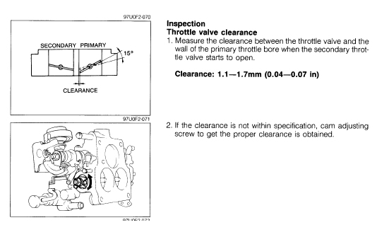
it is a 2 stage throttle body (primary ports/runner opens then secondary ports/runners open). This procedure sets when the secondary throttle plates open--the transition from the first to the second stage. It may have a moderate effect on the way the car drives but I didn't notice much. On the Rx-8's, the secondary ports have their own valves in the manifold. They are opened by a vacuum actuator controlled by the PCM.
I think you should just fiddle with it until it works, and I wish it were as easy using factory specs. The throttle adjust screw (with the locknut) is a coarse adjustment for the amount of intake air at idle. The bypass air screw under the TB is a finer adjustment. Further compensation is done by ignition timing advance and ISC valve duty cycle (if still equipped). There are so many things going on at once that you will find yourself turning screws like it's some kind of carburetor and then fiddling with the PFC to see what fuel and timing advance it likes best. There's a reason why people pay professionals a lot of money to set this up right.
What Arghx said. 
Before I got Chuck's notes, I bounced around the FSM from one section to next trying to figure this out. chuck's notes has a full how to w/ pics in one place simplifying the whole process. The FSM is informative but sometimes finding info in it is a task.
Before I got Chuck's notes, I bounced around the FSM from one section to next trying to figure this out. chuck's notes has a full how to w/ pics in one place simplifying the whole process. The FSM is informative but sometimes finding info in it is a task.
Trending Topics
I appreciate the responses and you guys watching the thread. I plan on subscribing to Chuck's notes, I was just waiting until I got the Datalogit. Which will probably be soon since I don't have an ISC and manual idle is tough without being able to better control the timing.
Here's where I am now. Set up the throttle body as best I could. Arghx is correct, some of this just involves adjusting and seeing what happens. But this morning I started the engine cold. Idle went up to 1500 - 1600 rpm and then warmed up and dropped down to 1200 where I was wanting it for now. So I think I have the fast idle close.
Last night I had backed the throttle adjusting screw off completely, set the TPS, and found it needed about 8 or 9 turns out on the air bleed to idle at 1200. So this morning I increased the throttle adjustment screw 1 turn (lined up the original paint mark), reset the TPS, and started it up. I was able to turn the air bleed screw in all the way and then out about 1/4 turn to get the idle where I wanted it. Does this sound OK?
I think I'm about ready to put the elbow on and hook up the IC piping. But here's my next question, and maybe I should ask it in the Power FC forum. I still think I am running rich. It smells rich. I have set the injector correction map down to about .77 in the cells surrounding the idle and am now idling at about 13.5 AFR.
I pulled both fuel rails out (all injectors have new o-rings but haven't been serviced) and turned the pump on - no leakage. I pulled the vacuum line off the FPR - no fuel there. Is there anything else to check which could cause it to run rich or is it just my imagination?
Running 550 primaries, 850s bored to 1300 for secondaries, and have a Supra pump. Fuel pressure at idle is within range I think. 28 to 30 cranking and 39 idling.
Any ideas,
Jeff

I'll be the first to admit I am just learning about rotaries. So maybe I'm being too suspicious. I don't smell any fuel in the engine bay. Don't see any evidence of any leakage. The car is still on stands in my garage so maybe that is part of the problem although I do have some ventilation through it. And no cat, just a resonated midpipe.
I was just a little surprised at how much I had to decrease fuel in the idle range in the injection map on the commander. I guess this map is different from the injection map I would see if I had a Datalogit so maybe this is just normal.
Anyway if there isn't anything else to check for flooding I'll continue like I am.
Thanks for the reply.
if anything, 13.5:1 is borderline lean on a car without an air pump, but that depends a lot on porting etc. The stock smog pump and port air control system in the ACV leans out the mixture before it reaches the stock O2 sensor. I would be careful. When you hot start it you might find some problems with idle stability as the IAT sensor heatsoaks.
It sounds like you have your TB set pretty well so far. The real test though is the idel after hot starts and the deceleration behavior.
It sounds like you have your TB set pretty well so far. The real test though is the idel after hot starts and the deceleration behavior.
I increased the fuel at idle to run a little richer.
You're right, idle after hot starts isn't working too well. It is much slower and eventually dies. Is this the condition where I should be setting my throttle screw or air bleed screw? I tried opening up the fast idle screw (the one which opens the throttle plates) but that didn't help.
You're right, idle after hot starts isn't working too well. It is much slower and eventually dies. Is this the condition where I should be setting my throttle screw or air bleed screw? I tried opening up the fast idle screw (the one which opens the throttle plates) but that didn't help.
I'm bringing this thread back from the dead because I had a question about the TPS adjustment that I don't quite understand.
On the FSM it states that when the car is fully warmed up, the fast idle cam roller should completely separate from the wax rod part. After checking my car, the fast idle cam only reaches point "D" on the markings, but I don't see it literally separate itself.
What I wanted to know is if the roller is supposed to go past point "D" and sort of fall on the side? Or is it supposed to reach point "D" and then sort of separate upwards or away from the wax rod part?
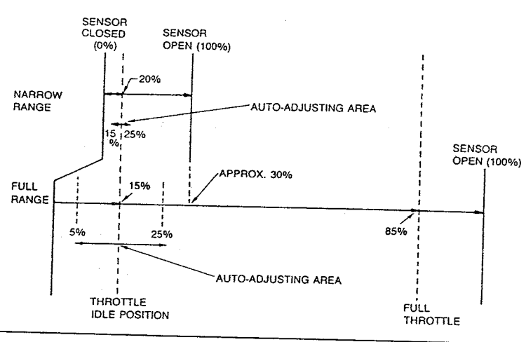
With the engine fully warmed up, check your TPS voltage. It's VTA1 and VTA2 in the Commander sensor/sw check screen. Look at VTA2 especially, which is the narrow range sensor. Now rotate the fast idle with your finger. Your TPS voltage should NOT drop if the fast idle system had already done its job closing the throttle plates once the engine warms up. If it noticeably drops then you most likely have a misadjusted fast idle system.
Joined: Mar 2001
Posts: 30,814
Likes: 655
From: FL-->NJ/NYC again!
From experience, I wouldn't worry about that. Make sure VTA1 is between 0.1 and 0.7 and VTA2 is between 0.75 and 1.25 with the engine warmed and throttle closed and you're good to go 


Joined: Mar 2001
Posts: 31,851
Likes: 3,239
From: https://www2.mazda.com/en/100th/
+1. i've played with this on a stock ECU car and its helpful.
the big tip is that a safety pin works great to probe the ECU pins, the pin part goes in, and the safety part holds the voltmeter lead.
second is that the stock ecu makes you do these adjustments in order, or it just punishes you, the PFC is probably better.
with the stock ECU, if the THROTTLE STOP HAS BEEN MOVED, you set the AAS first, mine likes to be 1.5 to 2 turns out, i've tried it with less, but it got cranky. then set the throttle stop, mine likes to be about the same as a carb, back the screw off and then tighten it until it touches, and then maybe 1/8-1/4 turn. then the TPS, i used the middle of the range, so 1v on the narrow range (and then whatever the wide range is). the throttle stop/TPS relationship has a huge impact on drivability. i guess the throttle stops were originally set to a certain airflow, and then the TPS, so these are related, and not in a way that is easy to figure out afterwards.
if the throttle stop has NOT been moved, then you can just set the AAS and TPS, and hopefully its fine

Thread
Thread Starter
Forum
Replies
Last Post
Jeff20B
1st Generation Specific (1979-1985)
73
Sep 16, 2018 07:16 PM