
running over 15 PSI? you need to know this.

Thread Starter


Joined: Oct 2001
Posts: 6,279
Likes: 728
From: Florence, Alabama
running over 15 PSI? you need to know this.
with the proliferation of single turbos and AI more and more FD pilots are turning up the boost.
of course you have to have all the ducks in a row and if you do the rotary is easily capable of cranking out 500 rear wheel hp... reliably.
given the Combustion Chamber Pressure (CCP) envolved when you are making 2-5 hp per cubic inch there are a few things that can spell instant motor doom.
i would like to draw your attention to one of the most lethal and probable.
whether you run the stock computer or a Power FC both the fuel map and ignition map reference off RPM and Load.
Load is the key. Load is determined by manifold vacuum or boost by the MAP sensor. (MAP being Manifold Absolute Pressure).
as most know, the MAP sensor bolts to the firewall near the brake reservoir. it connects to the engine using a small hose. the MAP sensor(whether stock of the often used GM 3 BAR) has a really nice lip on it to ensure that, w the addition of a tie wrap, the hose will not be blown off the unit.
////edit: after writing the above and not recently seeing a stock MAP sensor i actually am not sure that the stock sensor has a good lip or not... the GM unit has a really good lip. someone please let us know re the stock sensor lip////////
the other end of the MAP hose is where motors are blown.
we generally connect the MAP sensor hose to the engine using one of the 3 tubes at the rear face of the UIM. that's the problem... they are tubes w no retaining lips.
consider what happens when you have upped the boost, your right foot is on the floor and the hose blows off the UIM tube...
the computer senses no boost while the turbo is still making, say 18 psi. the computer immediately moves fuel and timing to a vastly different spot on the map.
instead of 15 degrees advance the engine receives 30 degrees. instead of 75-85% injector duty cycle the engine receives 20 or 30% duty cycle.
we are at redline and all of a sudden we have double the ignition advance and a quarter of the fuel.
all because of one hose being blown off!
as you know, there are around 9 tubes that we either use or cap off on the UIM, none have retaining lips. most, if they fail, will not cause engine failure.
in the 21st century enviornment w the ability to run 27 psi on pump gas and AI methanol reliably all of us need to rethink our pressure connections. i have a 3 inch lab grade pressure gauge and an adj regulator and it is easy to pressure up the connections to 30 psi to check integrity. i was really surprised as i headed towards 30 psi to see so many tie wrapped connections fail.
i welcome anyone's comments as to how they have uprated the connections. the simplist, though not necessarily the best, would be to make sure there is no grease on the tube (wipe it w alcohol) and use multiple tie wraps.
please do spend a moment and recheck your MAP hose at the UIM.
howard coleman
Joined: Aug 2005
Posts: 2,720
Likes: 1
From: Greenwood/Hartsville, SC.
Howard, is there a way to expand the opening of the tubes that come off of the UIM, thereby creating your own "lip"? If not, would some sort of epoxy be able to bond with the metal and rubber?

I suspect that a simple scuffing with sandpaper then laying a nice little bead of jb weld will work very well. You might want to sand down the JB Weld 'barb' a bit to make it easier to work with.
Another option would be to physically yank out the metal nipple from the manifold and tap in an NPT and use a barbed fitting.
FYI, assuming a .1" diameter hose, at 30 psi your 'blow off' force converts to .25lb. I suspect the jb weld method plus a zip tie is more than sufficient.
Dave
Another option would be to physically yank out the metal nipple from the manifold and tap in an NPT and use a barbed fitting.
FYI, assuming a .1" diameter hose, at 30 psi your 'blow off' force converts to .25lb. I suspect the jb weld method plus a zip tie is more than sufficient.
Dave

Thread Starter
Joined: Oct 2001
Posts: 6,279
Likes: 728
From: Florence, Alabama
setzep did it right.
since my manifold is off for winter i see some drilling and tapping in my future. you don't necessarily have to D&T all of the fittings as many of them won't cause engine failure.
your really do not want the MAP hose coming off.
guess how i know this.... it happened last Sep on the dyno. fortunately ace tuner Luke Stubbs got out of it w no motor damage. my hose had been tie wrapped.
i do not want to lose a motor to something simple to fix.
neither do you.
where' the drill?
howard
Trending Topics
This is a really important point. On my 2nd gen my OMP air bleed hose blew off the back of the UIM. For some bizarre reason that distorted my GM 3 bar MAP sensor reading, which was hooked to a port on the front of the UIM. So I was boosting 21psi (race fuel), but my power FC only read 10psi! The timing was advanced too far by about 8 degrees, and the AFR leaned out to 15:1 at 21 psi!
The result was INSANE detonation. The porcelain separated from 3 of my 10 heat range spark plugs! I cracked a corner seal. But RA super seals survived and I am actually reusing them on my next motor as they look brand new almost and passed every FSM test.
One soluton: A small bit of Krazy Glue. Seriously. you will have to cut the hose off to remove it (MAP sensor hose isn't so bad to replace), but it will NEVER blow off. Good to 25+psi . For my actual MAP sensor, I actually use a 3/16" fuel line hose from autozone on my FC, I have it clamped with a small hose clamp on a nipple on the front of my 2nd gen UIM (smallest size clamp you can get there). The 3/16" hose will fit very very tightly on the GM 3 bar sensor (b/c of the lip on the nipple), nothing extra needed.
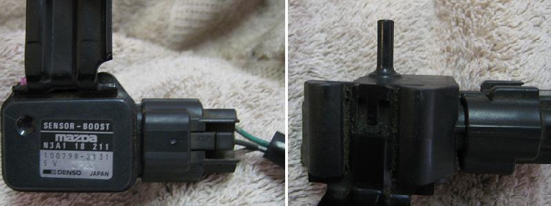
Here's a photo of the stock MAP sensor (Mazda calls is a Boost Sensor ). A little sandpaper and crazy glue sounds like a very good idea. Might be wise to make sure all the other vacuum lines on the UIM are secure also (especially the one connected to the fuel pressure regulator)... as mentioned above, any boost leak large enough to distort the vacuum that the MAP sensor measures could result in a pretty catastrophic failure.
-s-
-s-
Last edited by scotty305; Feb 28, 2009 at 04:45 PM.
Thread Starter
Joined: Oct 2001
Posts: 6,279
Likes: 728
From: Florence, Alabama
scotty305 makes a real good point.
we need to add to the list of absolutely locked down connections the line from the UIM to the aftermarket fuel pressure regulator.
let's assume we are at max boost, say 25 psi, and that line pops off the UIM tube. fuel pressure goes from 65 psi to 40 psi. at 25 psi boost. ooops.
where's the drill and tap?
and thanks for the MAP sensor pic. that sure looks like an accident waiting to happen. CrazyGlue (along w tie wraps) sounds like it might work... anyone have an informed opinion?
hc
Last edited by Howard Coleman; Feb 28, 2009 at 07:55 PM.
Another important thing here is running the RIGHT vacuum line. If it doesn't fit well to begin with, you'll always have problems.
I have always run 3.5mm Hose Techniques silicone vacuum line. It fits VERY tight on all the stock nipples, and requires a good deal of force to remove. Granted I don't run 20+ psi of boost (right now about 12-13 psi) but I've NEVER had a line pop off. I don't have any of them zip-tied either.
The FPR and MAP sensor lines are absolutely critical - this is definitely true. Same goes for any lines for a boost controller.
Few good things to make CERTAIN of. This goes for any FD, not just cars running a lot of boost.
- NEVER NEVER NEVER use plastic vacuum tees. I personally know of 2 people who lost motors due to these failing. The heat under the hood is just too much. They're fine on Grandma's Buick, not an FD. If you have to use a tee, use BRASS. For small size tees, you can find brass ones at the aquarium section of most pet stores for cheap, and they hold up and work/fit great. For larger size, like wastegate hoses (6mm), some parts stores might have them, but McMaster-Carr is a great source, they have really good ones for cheap.
- NEVER NEVER NEVER tee anything in to the MAP/FPR sensor signal. You want that signal as clean as you can make it. Also, tees, even using good brass tees, introduce a potential failure point.
- NEVER NEVER NEVER use cheap vacuum caps. The ones from the parts stores WILL FAIL. The heat bakes and cracks them, and that's it. McMaster-Carr sells good fitting vacuum caps in a variety of sizes. I've been using the EPDM rubber caps they make, good to 450 degrees, for years now with zero failures. They're dirt cheap for a big bag of them too.
Also, there's always a debate about using viton or silicone vacuum hose. I have worked with cheap silicone vacuum hose in the past, and it IS crap. GOOD QUALITY hose, like from Hose Techniques.com, will not let you down. I've been using their hose for 10 years now on turbo FC's and FD's and have had ZERO failures. I do use Viton line from the oil neck to my catch can - that is just way too much oil vapor for silicone line to tolerate, even good stuff. Viton stretches much less than silicone, and I'm not sure how "grippy" it is to prevent a hose from popping off. 3.5mm and 6mm hose from Hose Techniques does the trick - it's reasonably priced and will last the life of the car.
If you're running a single turbo with a very simple vacuum hose setup, I think it would be worth re-thinking the whole vacuum line setup. Remove and weld over the stock vacuum nipples that you don't need. If you run a GM 3-bar, drill/tap a 1/8" NPT hole in the UIM for a threaded brass hose barb that's 6mm size - the 3-bar sensor (if memory serves) takes a larger size vacuum line, and running some sort of adapter to go from small to large doesn't cut it. You have to stop and carefully consider each part of the system and how it could fail.
Dale
5/32" is about the closest to 3.5mm you are going to get in a nominal standard size from my experience, having bought hose that was listed in standard sizes. i think I am going to order 5/32" vacuum caps from McMaster-Carr, part # 6448K74 :
http://www.mcmaster.com/ctlg/DisplCt...54344087987953
and do not bother with autozone brand silicone hose ("3A Racing" or whatever). you can just feel how cheap it is compared to the real stuff from hose techniques. And I think zipties are worthless. I have done a lot of pressure testing of my whole air system and have found that they make no difference. You can't get enough torque on them--only worm gear clamps can do that, and you can't get ones that will fit over the small hoses from what I can see. The most important thing is tightly fitting hose.
I run my wastegate lines in stainless steel. It's the only thing I trust. You can get all the fittings and such or just use a worm clamp. it's a bit ghetto looking but it works, although be careful not to get pricked.
400Rwhp Seq Twins Baby!!
Joined: Mar 2006
Posts: 362
Likes: 0
From: "Sunny" ol England
Years ago after a dyno session, the shop actually left the map sensor loose after the run. I got about 30 yards down the road before the car just crapped out on me. After that I taped it up until I got home and secured it propperly.
I used a small tapper and knocked the end with a hammer until it stretched abit of the end and created a little lip. Then used zip ties to secure. Granted its not as effective as some of the above but I've not had problems with it at 18psi
I used a small tapper and knocked the end with a hammer until it stretched abit of the end and created a little lip. Then used zip ties to secure. Granted its not as effective as some of the above but I've not had problems with it at 18psi
So what would be the best size caps to use? Would it be the 5/32" like arghx member stated?

It may be possible to use a brake line flaring tool to make a lip on the end of the factory vac. line. The end of the tool is a cone and there is a die type device you may be able to clamp on the line and then use the cone to press a lip on it. I would recommend trying it on a junk manifold or something else just in case it does not work. You can find picture of the tool online with google. It would be interesting to see if it does work. I havent heard of the lines blowing off before, I have done many 22psi nissans and those are straight non flared vac fittings. But if it does work I would do it just for the extra peace of mind. Let me know if some one does try it and it does work.
Darkside FD
Joined: Jan 2004
Posts: 1,175
Likes: 0
From: AZ
I used to use a little red loctite on the nipple and then push the silicone line over it. It would make the line VERY secure on the nipple. I would have to cut the silicone to remove it most times. Just make sure it cures before doing max boost type runs. Superglue is similar but dries too fast for me. Going to straight AN fittings would be best in most cases (especially at the wastegate) but how would you attach an AN to your map sensor?
In my case I lost the engine when the banjo bolt on the wastegate came loose and fell off at full throttle. The hose stayed on the nipple though Funny part about that is I had ordered the AN fittings to re-do the wastegate lines because I was paranoid. They got to my house two days after my engine blew up... talk about bad irony.
In my case I lost the engine when the banjo bolt on the wastegate came loose and fell off at full throttle. The hose stayed on the nipple though
Funny part about that is I had ordered the AN fittings to re-do the wastegate lines because I was paranoid. They got to my house two days after my engine blew up... talk about bad irony.
R1derful
Joined: Feb 2004
Posts: 702
Likes: 0
From: N Cali
Great post. On a lot of FDs, the hose leading to the MAP sensor is baked.
I had the hose blow off of the map sensor side on my old FD. This happened while it was under load, too. Scared the hell out of me and I was sure that I hurt something. I had a J&S Safeguard in that car (set to pull a max of 10 deg to avoid negative timing split), and it went crazy with pulling timing when the hose came off.
I sandpaper'd the nipples and used Hose Techniques hoses. Never had a problem after that. This was with 12-13 psi of boost. I might not have been so lucky with more boost.
Sonny

this is great info as I am currently switching my hoses around. Today i was installing my new fuel system, and the comment about NEVER t-ing into the MAP or FPR lines got my attention as I was just about to do it.
The two hose fittings at the base of the LIM that are burried by the fuel system are impossible to get to without removing the fuel system. For this reason, I was going to remove rear fitting that goes to the stock FPR, as my new FPR will be in the front. So I was going to just cap that fitting off (no barb uh-oh).
The front fitting currently goes to my boost controller, and is right where my FPR and boost controller will be. So I was going to T into this for both. If this is a no-no, and I want to avoid using the rear fitting which is completely buried, what is the optimal spot to locate the boost controller source (I'll leave the new FPR hooked to the front fitting that is buried). Is it safe to T into the hose that goes straight from the UIM to the Blow-off valve? Its in the same area and would be easy to get to.
And I capped the rear nipple off today before i read this thread. I rubbed high temp orange RTV on the fitting, put a pretty thick cap on it, two zip-ties, and then a tine squeeze hose clamp (like a radiator clamp that works with pliers). I don't know where to find a worm clamp that small anywhere. I won't be running over 24psi, i have not finished the fuel install yet, so i can go back and redo it if needed, not sure how i could do any better though.
This thread makes me think that a MAF (mass air flow) based system would have been better. I never really got a good argument as to why MAP (manifold pressure) based systems were used in place of a MAF type... especially on a turbochaged car... Anyway, good points on how to ensure system integrity... I echo the statements regarding securing the MAP line and the FPR line.
Darkside FD
Joined: Jan 2004
Posts: 1,175
Likes: 0
From: AZ
A lot of the V8 guys run speed density off of just the MAP sensor but it isn't as precise. IT is strange that an engine as reliant on tuning (they all are, but the rotary moreso) as the 13brew, would run only off the MAP sensor.
1. 2nd gens had both an airflow sensor and a MAP sensor from the factory (and EFI 1st gens had just an airflow meter). It has nothing to do with how modern or un-modern the car is.
2. running just a MAP sensor in speed density configuration cut down the cost on a car that was already really expensive and complex.
3. Mazda does not design their cars with hardcore aftermarket tuners in mind, nor should they have to.
2. running just a MAP sensor in speed density configuration cut down the cost on a car that was already really expensive and complex.
3. Mazda does not design their cars with hardcore aftermarket tuners in mind, nor should they have to.