Rewrap Harness
 05-27-12, 05:12 PM
#26
On the smog pump connector can that be repaired without sourcing new connector?
I think on the knock sensor the actual wires are semi cut.
Probably would be best to remove all the loom and electrical tape so I can see whats damaged and get repaired, kind of wanted to avoid doing that and just rewrap over like you said, would be easier.
I think on the knock sensor the actual wires are semi cut.
Probably would be best to remove all the loom and electrical tape so I can see whats damaged and get repaired, kind of wanted to avoid doing that and just rewrap over like you said, would be easier.

 05-27-12, 06:22 PM
#28
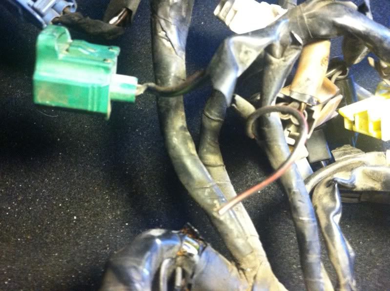
the knock sensor doesn't really require many strands of wire for the signal but it does need good continuity so no corrosion for the best accuracy. still doesn't look like a big issue with that one to me.
the red wire below looks like the 110C auxiliary water temp sensor wire, it's the single pin connector just below the water thermosensor on the back of the water pump housing.
the smog pump connector can be replaced by cutting the connector off the smog pump and replacing both ends which whatever 2 pin generic connector floats your boat. some auto parts stores will have both ends of various connectors in the electrical section.
most of those connectors are first to fail due to their location, same connectors broken here:
https://www.rx7club.com/3rd-generation-specific-1993-2002-16/name-plug-game-999580/
Last edited by RotaryEvolution; 05-27-12 at 06:25 PM.
05-30-12, 02:24 PM
#33

http://www.youtube.com/watch?v=KkhIP...&feature=g-upl
bring a friend
Just kidding, the video isn't just re-wrapping, I actually cut all the old wiring out and replaced it with brand new wiring, basically just kept about 3" of wiring at each harness and soldered new wiring on. the wrapping part (near the end) took virtually no time at all.
bring a friend
Just kidding, the video isn't just re-wrapping, I actually cut all the old wiring out and replaced it with brand new wiring, basically just kept about 3" of wiring at each harness and soldered new wiring on. the wrapping part (near the end) took virtually no time at all.
06-01-12, 04:31 PM
#34
Okay im going to start taking off the tape and wiring loom here soon. Just to clarify a few things on rewrapping.
1. Going be ziptying every 6 inches and at the branches during tape removal, Do I wrap over the zip ties or take them off when rewrapping?
2. Do I use tape under the loom as well? I guess extra protection wont hurt.
3. What tape do you use? Silicone? Anything high temp will work? I have read friction tape is what karack uses but doesnt say anything about it protecting against high heat?
4. Would this loom work well? http://www.summitracing.com/parts/RFW-ZL12 Would you recommend a high temp flame retardant wiring loom?
5. Also is there a way to really protect the ends of the wiring where they go in the connectors? Seem so easy to break plus their semi exposed.
TIA
Last edited by jayscoobs; 06-01-12 at 04:37 PM.
06-03-12, 10:31 AM
#35
https://www.rx7club.com/showthread.p...ghlight=Fusion
Personally I liked the silicone fusion tape. But there are options/opinions.
Personally I liked the silicone fusion tape. But there are options/opinions.
06-03-12, 04:01 PM
#38
Your idea is still recommending not taking off the old tape? And just wrap with the friction tape over orginal harness? Kind of feels fragile with some of the brittle plastic breaking when squeezed.
I guess the main question is how can I test continuity without taking off all the tape? Bundled part of harness seems too thick and I just dont know where to touch with multimeter. One goes on a connector pin? and one goes where?
Can I just take off and rewrap all the branches? thats where the brittle parts are.
Im just trying to figure out best way. If I did take off old wrapping id replace the wiring that looks like would need replacing.
Last edited by jayscoobs; 06-03-12 at 04:05 PM.
06-05-12, 08:55 AM
#41
2 methods, 1 is to wrap over the original looms, other is to carefully strip all the looming off and rewrap the whole harness over again. the latter would probably require more attention paid to the engine connectors as a few of them will likely have insulation showing after working on the harness cutting it open.
heat can also play a factor in working with the harness, if it is brittle in some areas then lay it in the sun before working on that section and it will probably make the wiring insulation pliable enough to work with temporarily.
same applies to working with the vacuum lines when replacing them and trying to avoid breaking the solenoids.
Last edited by RotaryEvolution; 06-05-12 at 08:58 AM.
06-05-12, 01:45 PM
#42
Okay, can I check continuity with all the tape still on? I just want to take apart to make sure all is well but don't want to damage at same time. Im going be having a second JDM harness that I can take wires and connectors from actually.
The JDM harness should be in better shape but I don't want to deal with trying to get it to work.
Im thinking of using this BTW http://www.homedepot.com/h_d1/N-5yc1...&storeId=10051
The JDM harness should be in better shape but I don't want to deal with trying to get it to work.
Im thinking of using this BTW http://www.homedepot.com/h_d1/N-5yc1...&storeId=10051
06-06-12, 04:14 PM
#43
Senior Member

Join Date: May 2001
Location: laurel, md usa
Posts: 297
Likes: 0
Received 0 Likes
on
0 Posts
You are in luck!! This is great oppertunity for you to do something you aren't good at. Now be an enthusiast and man up  .
.
Re-wraping a harness is extremely easy. But it can be intimidating for someone who doesn't keep things organized. All you have to do is follow these simple steps, and you are home free.
Tools:
Razor blade
Electrical tape (2-3 roles)
Zip ties
Wiring loom 1/2" & 1"
Steps:
1. Remove the harness (you would have had to do this anyway, so no excuse here)
2. Take a razor and slowly cut away at the old tape
3. Remove the wiring loom
4. As you remove the loom, place a zip tie around the harness wires every 6 inches, and at every wiring branch from the main piece. This keeps the same shape as the original harness. Now you have a wiring harness that is bare wire, but in the exact same shape as it was.
5. Now re-loom the harness. Cut small lengths for each branch. Cut a long length for the main piece. The loom slides right on.
6. Wrap the loom with electrical tape. Put extra wraps around the joints of the branches where the loom meets. As you get to the end of the branches where the connectors are, wrap the wire up and add a small zip tie to keep things tight.
DONE!!
.Re-wraping a harness is extremely easy. But it can be intimidating for someone who doesn't keep things organized. All you have to do is follow these simple steps, and you are home free.
Tools:
Razor blade
Electrical tape (2-3 roles)
Zip ties
Wiring loom 1/2" & 1"
Steps:
1. Remove the harness (you would have had to do this anyway, so no excuse here)
2. Take a razor and slowly cut away at the old tape
3. Remove the wiring loom
4. As you remove the loom, place a zip tie around the harness wires every 6 inches, and at every wiring branch from the main piece. This keeps the same shape as the original harness. Now you have a wiring harness that is bare wire, but in the exact same shape as it was.
5. Now re-loom the harness. Cut small lengths for each branch. Cut a long length for the main piece. The loom slides right on.
6. Wrap the loom with electrical tape. Put extra wraps around the joints of the branches where the loom meets. As you get to the end of the branches where the connectors are, wrap the wire up and add a small zip tie to keep things tight.
DONE!!
You may want to find a source for those small male and female pin contacts inside the connectors. A few years back I googled "japanese electrical connectors" found a motorcycle shop in West Virginia that sold these as well as the seals.
Where do the solenoid connectors ground(b/w)? I've looked at the wiring diagrams, think its the ground under the coils but I dont have continuity there. While you have this out can you check and photograph the end?
Thanks Karack for identifying the knock sensor connector.
06-06-12, 09:14 PM
#45
Senior Member
Join Date: May 2001
Location: laurel, md usa
Posts: 297
Likes: 0
Received 0 Likes
on
0 Posts
black wire white stripe. each of the 8 like kind solenoids have one. only able to find continuity back to the EGI relay on driverside fender.
illustration in wiring manual has it grounding closer to the engine either near the air conditioner and vacuum chamber. I havent found a ground point with continuity there.
Since you had it apart and was embarking on wire repair. I thought to ask if you could check if your terminated at the ground under the coil. or if you found it terminated some where else.
the place I got the electrical contacts was motorcyclecarbs.com out of Kennesaw, GA. I have quite a few I'll never use them all, If you PM me I'll mail you some if you want.
06-06-12, 10:53 PM
#46
What electrical contacts are you talking about?
Im not sure where the ground came from because im restoring a rx7 and I bought the harness off a forum member. So were piecing it together, my friends with more knowledge on this would be able to answer probably.
Im not sure where the ground came from because im restoring a rx7 and I bought the harness off a forum member. So were piecing it together, my friends with more knowledge on this would be able to answer probably.
06-07-12, 11:07 AM
#48
Senior Member
Join Date: May 2001
Location: laurel, md usa
Posts: 297
Likes: 0
Received 0 Likes
on
0 Posts
I think I got confused with 2 things seeing a B/W wire on the ground under the coil, and misinterpret the circle 15 by the egi relay as a ground in the wire schem.
So on these solenoid leads I check b/w for continuity back to the EGI relay, and the other colored lead back to the slots on the ECU?
So on these solenoid leads I check b/w for continuity back to the EGI relay, and the other colored lead back to the slots on the ECU?
06-10-12, 10:54 PM
#50
Okay I got busy and ended up not doing harness. I really dont want to take it apart and hope to just wrap over existing harness.
Now I want to make sure theres continuity. Im having trouble understanding the diagram so to check can I just touch a connector wire and just touch and go through all the wires at the ECU plugs and hope for a reading?
Now I want to make sure theres continuity. Im having trouble understanding the diagram so to check can I just touch a connector wire and just touch and go through all the wires at the ECU plugs and hope for a reading?