
Re-connecting boost controller


Re-connecting boost controller
So I've been driving around for quite a while without a boost controller because for some reason my turbos were having problems. I had my boost controller disconnected because I thought it was the problem, but I want to reconnect it to see if it is the problem. I don't know what the guy did, but there are hoses under my hood that are disconnected and he said that it is for the boost controller. I don't want to bring it back and get charged, so I'm looking to try and do this myself. Is it hard to connect everything back? All the electrical stuff is still working, just nothing is connected for the engine and stuff. If someone could help me do this, that would be great.


Full Member
Joined: Mar 2004
Posts: 61
Likes: 0
From: Oceanside CA
It might be like my Apexi and it is the lines on the side of the control valves that are facing the driver side and you need disconnect them from the ones running to the rats nest and block them off (on the valves).
Trending Topics
Rotary Freak
Joined: Sep 2004
Posts: 2,444
Likes: 0
From: Bay Area, CA
Rotary Freak
Joined: Sep 2004
Posts: 2,444
Likes: 0
From: Bay Area, CA
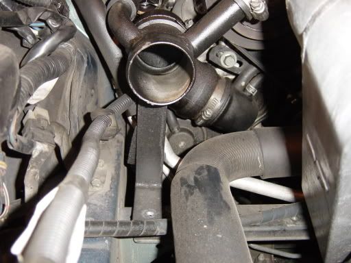
2nd 4th and 5th, if he did anything with the hoses in the 3rd pic the boost guage wouldn't work.
And now that I think about it since the pills are removed if he returned the hoses to stock then you should be only seeing 7psi. I'd be interested to know what exactly he did to "disable" the boost controller.
And now that I think about it since the pills are removed if he returned the hoses to stock then you should be only seeing 7psi. I'd be interested to know what exactly he did to "disable" the boost controller.
Last edited by BlueRex; Aug 30, 2006 at 01:37 AM.
I don't know, but I know for sure there are two hoses that are not connected and he zip tied them together. My boost controller electronics still work and still reads/records everything. The boost gauge still reads and I'm still boosting 10-8-10, but couple times when I get on it, it has spiked to 13-14psi which is why I want to reconnect and get the controller working right away. Not boosting it until this is fixed.
I checked it out today and the two hoses that are disconnected are the ones in picture #4. It's connected to the splitter but they are not connected on the other end. Where should these be going to?
Then I can't even figure out where the other ones are by the pictures, could you help me out Jason?
Then I can't even figure out where the other ones are by the pictures, could you help me out Jason?
Rotary Freak
Joined: Sep 2004
Posts: 2,444
Likes: 0
From: Bay Area, CA
Originally Posted by HardHitter
I checked it out today and the two hoses that are disconnected are the ones in picture #4. It's connected to the splitter but they are not connected on the other end. Where should these be going to?
Then I can't even figure out where the other ones are by the pictures, could you help me out Jason?
Then I can't even figure out where the other ones are by the pictures, could you help me out Jason?
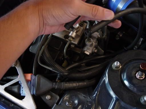
Pic 2 is the actuator under the intake for the primary turbo.
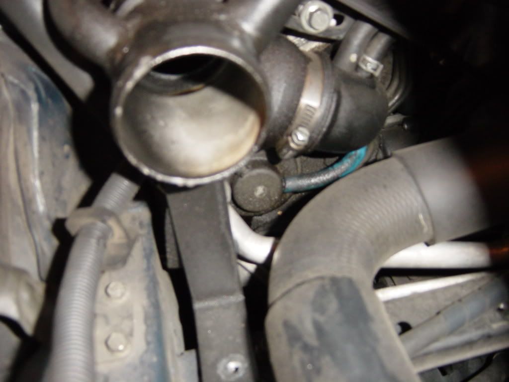
Pic 3 is the splitter for the boost guage and boost controller.
Pic 4 is the solenoid mounted near the ABS.
Pic 5 is the other side of the actuator under the primary intake. The hoses in this pic should be running to the solenoid.
It's been a while since I installed that, but if you need help just give me call between 5-8 and I'll see if I can help you.

quick question...the hose connected to the actuator, does it run to the left selenoid or the right? (looking at it from the passanger side) does that make sense?
Last edited by LovMyRx7; Aug 30, 2006 at 03:06 PM.
They are plugged into the solenoid, but the other ends are not connected to anything, that's what I'm trying to figure out what they need to be connected to and which one to which.
Rotary Freak
Joined: Sep 2004
Posts: 2,444
Likes: 0
From: Bay Area, CA
I forgot. You have to read the Greddy manual I gave you. One is labeled COM and the other OUT (?) can't remember. If you can post up that part of the manual I can tell you guys. I also think that the COM nipple is referred to as IN in the manual (not positive as it's been a while since this was done). Following version 1 in this link:
https://www.rx7club.com/3rd-gen-archives-73/profec-b-spec-ii-install-review-192249/
Blue goes to IN (or COM), red goes to OUT. Double check this for yourself in the manual.

https://www.rx7club.com/3rd-gen-archives-73/profec-b-spec-ii-install-review-192249/
Blue goes to IN (or COM), red goes to OUT. Double check this for yourself in the manual.
Last edited by BlueRex; Aug 30, 2006 at 08:02 PM.
Jason,
So I just need to connect those two hosees and I should be set right? Those are the only hoses that I can see are not connected to anything. Also, where is that in the engine bay again? Do I need to remove anything? It looks as if something is taken off in order to get to where you're supposed to connect those hoses.
So I just need to connect those two hosees and I should be set right? Those are the only hoses that I can see are not connected to anything. Also, where is that in the engine bay again? Do I need to remove anything? It looks as if something is taken off in order to get to where you're supposed to connect those hoses.
Rotary Freak
Joined: Sep 2004
Posts: 2,444
Likes: 0
From: Bay Area, CA
Originally Posted by LovMyRx7
says that version one is "unable to maintain the same boost levels, especially in different climates and temps", you had this problem Blue?
Originally Posted by HardHitter
Jason,
So I just need to connect those two hosees and I should be set right? Those are the only hoses that I can see are not connected to anything. Also, where is that in the engine bay again? Do I need to remove anything? It looks as if something is taken off in order to get to where you're supposed to connect those hoses.
So I just need to connect those two hosees and I should be set right? Those are the only hoses that I can see are not connected to anything. Also, where is that in the engine bay again? Do I need to remove anything? It looks as if something is taken off in order to get to where you're supposed to connect those hoses.
1) Reconnect the hoses.
2) Make sure the other nipples are capped off.
3) Check the electrical connector to the solenoid.
4) Make sure everything is still plugged in back of the controller itself.
That's all I can think of.
The actuator with the hoses in the picture above is under the intake for the primary turbo. You will have to remove the lower of the 2 greddy intakes to get to it.
I checked it out today. Took off the air filters and I think im checking the right place but the hoses are connected there? Here are pics I took.
These are the hoses that are disconnected
Place where i think they are supposed to go, but theres hoses there already?
These are the hoses that are disconnected
Place where i think they are supposed to go, but theres hoses there already?
Rotary Freak
Joined: Sep 2004
Posts: 2,444
Likes: 0
From: Bay Area, CA
Originally Posted by HardHitter
No, they are the ones that are not connected to anything as you can see. THose are the ones coming from the splitter.
Just follow all the pics and instructions I've already posted if you want to reconnect the Greddy boost controller.
So if I get this right. In my picture. The blue hose should be disconnected and that should be capped off correct?
Then the two hoses that are disconnected, I need to hook them up. The two disconnected hoses are going to replace the hoses that are marked by the red and blue dot in your picture correct?
Then the two hoses that are disconnected, I need to hook them up. The two disconnected hoses are going to replace the hoses that are marked by the red and blue dot in your picture correct?