Questions before undertaking Turbo rebuild...
 03-01-04, 08:48 PM
#51
il Cosa Nostra e vivo!!
Thread Starter
iTrader: (1)
Join Date: May 2003
Location: Dove le cose sono fatte il vecchio moda il senso
Posts: 2,097
Likes: 0
Received 0 Likes
on
0 Posts
I got started on this project about an hour ago and was able to take off all oil supply line and the water cooling lines. Then it was time to take off the 10mm bolts (6) that hold the Turbo onto the Manifold. Had to bang it a little for the Secondary Turbo to slide off. And it did!  The big C-Clamp that holds the intake turbine and shaft assembly/compression turbine is going to be a Father Mocker to take off. I'll resume the rebuild tomorrow and post more photos. For now, I have to go feeds my little childrens and call it a night.
Here's a photo of the Turbos on the maniflold.(Pre-Rebuild)..

The big C-Clamp that holds the intake turbine and shaft assembly/compression turbine is going to be a Father Mocker to take off. I'll resume the rebuild tomorrow and post more photos. For now, I have to go feeds my little childrens and call it a night. Here's a photo of the Turbos on the maniflold.(Pre-Rebuild)..
Last edited by dgeesaman; 06-18-07 at 11:21 AM.
 03-01-04, 09:01 PM
#52
il Cosa Nostra e vivo!!
Thread Starter
iTrader: (1)
Join Date: May 2003
Location: Dove le cose sono fatte il vecchio moda il senso
Posts: 2,097
Likes: 0
Received 0 Likes
on
0 Posts
Here's the Secondary Turbo out of the Manifold. I can't wait to open the sucker up!! So far no major snags,...But the rebuild is young!!

So far no major snags,...But the rebuild is young!!Last edited by dgeesaman; 06-18-07 at 11:21 AM.
03-01-04, 09:11 PM
#53
il Cosa Nostra e vivo!!
Thread Starter
iTrader: (1)
Join Date: May 2003
Location: Dove le cose sono fatte il vecchio moda il senso
Posts: 2,097
Likes: 0
Received 0 Likes
on
0 Posts
Here's a close-up of the big C-Clamp that needs to come off in order to get acces to the Turbine Shaft and Seals...
Last edited by dgeesaman; 06-18-07 at 11:22 AM.
03-01-04, 10:15 PM
#55
il Cosa Nostra e vivo!!
Thread Starter
iTrader: (1)
Join Date: May 2003
Location: Dove le cose sono fatte il vecchio moda il senso
Posts: 2,097
Likes: 0
Received 0 Likes
on
0 Posts
CORRECTION. In my last few posts I made reference to the "big C-Clamp' that holds the Turbo housing halves together. That is a mistake. What I meant to say/write was big "Snap-Ring". Sorry for any confusion I caused. Thanks. -Jimmy
03-02-04, 11:02 PM
#57
il Cosa Nostra e vivo!!
Thread Starter
iTrader: (1)
Join Date: May 2003
Location: Dove le cose sono fatte il vecchio moda il senso
Posts: 2,097
Likes: 0
Received 0 Likes
on
0 Posts
Originally posted by BoOsTin FD
Update? I like the pics so far
Update? I like the pics so far
It is really amazing how easy it is to do the rebuild. The most important part is making sure you mark the housing(s) and wheels before removal. The biggest PITA was removing the assembly off the Engine.
Anyway, thanks for your interest. If ANYONE needs photos of any specific part of the rebuild, just let me know. I can post any frame/photo of any part of the rebuild.
03-03-04, 10:19 AM
#59
il Cosa Nostra e vivo!!
Thread Starter
iTrader: (1)
Join Date: May 2003
Location: Dove le cose sono fatte il vecchio moda il senso
Posts: 2,097
Likes: 0
Received 0 Likes
on
0 Posts
Originally posted by Just Bring It
I would like if you could post a picture of this Marking that you did. I have no idea what am i suppose to mark when taking them appart.
I would like if you could post a picture of this Marking that you did. I have no idea what am i suppose to mark when taking them appart.
Marking the Compressor/Bearing Housing prior to disassembly is vital. The mark will get you back to the exact point and configuration of the Housings before the rebuild was started.
Here's a photo of where I placed my mark.....
Last edited by dgeesaman; 06-18-07 at 11:22 AM.
03-03-04, 10:26 AM
#60
il Cosa Nostra e vivo!!
Thread Starter
iTrader: (1)
Join Date: May 2003
Location: Dove le cose sono fatte il vecchio moda il senso
Posts: 2,097
Likes: 0
Received 0 Likes
on
0 Posts
The next step is to take the big snap-ring off the Compressor Housing. You'll need an extra large set of snap-ring pliers to accomplish the procedure. Once that's done, the Bearing Housing can be pulled out of the Comp-Housing.
This is a photo of the Bearing Housing after it was pulled....

This is a photo of the Bearing Housing after it was pulled....
Last edited by dgeesaman; 06-18-07 at 11:23 AM.
03-03-04, 10:55 AM
#61
il Cosa Nostra e vivo!!
Thread Starter
iTrader: (1)
Join Date: May 2003
Location: Dove le cose sono fatte il vecchio moda il senso
Posts: 2,097
Likes: 0
Received 0 Likes
on
0 Posts
Now the real fun begins.
In order to get to the internal components of the Bearing Housing, the Compressor Wheel will have to be taken off. BEFORE YOU DO THIS,..MAKE SURE YOU MARK BOTH WHEELS in relation to their location on the Bearing Housing. These marks will place the wheels back exactly where they were before they were taken off, which will keep the wheels/shaft balanced.
After making all the marks, you can start taking off the Comp-Wheel. This is done by taking off the Com-Wheel Nut. The Turbine Wheel (on the opposite end) has a built-in 12mm nut on the end that can be wrenched and held as you're taking off the Comp-Wheel Nut.
After the Comp-Wheel comes off, you'll have to twist and pull as it works it way out of the Shaft. After it comes off, the Turbine Wheel can be pulled out of the Bearing Housing from it's end. With that accomplished, it's now time to take off the Bearing Housing Cover. It will will have to be popped out with a punch. Once taken off, it will expose the Thrust Bearing and the Shaft Bearing.
Here's a photo that illustrates the parts after disassembly
Last edited by dgeesaman; 06-18-07 at 11:23 AM.
03-03-04, 11:22 AM
#62
il Cosa Nostra e vivo!!
Thread Starter
iTrader: (1)
Join Date: May 2003
Location: Dove le cose sono fatte il vecchio moda il senso
Posts: 2,097
Likes: 0
Received 0 Likes
on
0 Posts
I'll have to go tonight and buy a small Snap-Ring Pliers to get to the Turbine side Shaft Bearing. I'll post more photos late tonight or tomorrow of the completed Secondary Turbo Rebuild.
For now,...here's a photo of the components after I cleaned them up a little. The old Turbine Seal, which is installed right below the Turbine Wheel, was broken,.. as was the old O-Ring that goes between the Bearing Housing and Bearing Housing Cover. They may have been the culprits causing the Turbo smoking a little???

For now,...here's a photo of the components after I cleaned them up a little. The old Turbine Seal, which is installed right below the Turbine Wheel, was broken,.. as was the old O-Ring that goes between the Bearing Housing and Bearing Housing Cover. They may have been the culprits causing the Turbo smoking a little???
Last edited by dgeesaman; 06-18-07 at 11:24 AM.
03-03-04, 11:27 AM
#63
il Cosa Nostra e vivo!!
Thread Starter
iTrader: (1)
Join Date: May 2003
Location: Dove le cose sono fatte il vecchio moda il senso
Posts: 2,097
Likes: 0
Received 0 Likes
on
0 Posts
JUST A QUICK NOTE: I'm really having alot of fun doing the rebuld. The "MaxCoopers" and "Jimlabs" of this Forum could do this rebuild blind-folded (and probably in half the time it's taken me . Seriously, it's a real simple process. Anyone can do it.
More pictures tomorrow.
. Seriously, it's a real simple process. Anyone can do it.More pictures tomorrow.
Last edited by areXseven; 03-03-04 at 11:30 AM.
03-03-04, 06:15 PM
#65
il Cosa Nostra e vivo!!
Thread Starter
iTrader: (1)
Join Date: May 2003
Location: Dove le cose sono fatte il vecchio moda il senso
Posts: 2,097
Likes: 0
Received 0 Likes
on
0 Posts
I'll shoot and post a photo later this evening comparing the new & old Bearings with measurements taken with my Dial Calipers. The old bearings should show some wear. Additional photos of the rebuild will also be posted. Thanks.
03-03-04, 09:10 PM
#69
il Cosa Nostra e vivo!!
Thread Starter
iTrader: (1)
Join Date: May 2003
Location: Dove le cose sono fatte il vecchio moda il senso
Posts: 2,097
Likes: 0
Received 0 Likes
on
0 Posts
Originally posted by MakoRacing
Id blow up my turbos some how if I tried to rebuild them...
Id blow up my turbos some how if I tried to rebuild them...
03-03-04, 11:05 PM
#71
il Cosa Nostra e vivo!!
Thread Starter
iTrader: (1)
Join Date: May 2003
Location: Dove le cose sono fatte il vecchio moda il senso
Posts: 2,097
Likes: 0
Received 0 Likes
on
0 Posts
Originally posted by alberto_mg
thanks for the write up and pics.
are you doing anything to fix cracks in the manifold that goes between the engine and the turbos?
thanks for the write up and pics.
are you doing anything to fix cracks in the manifold that goes between the engine and the turbos?
BTW, I installed all the new parts (two Shaft Bearings and The Thrust Bearing w/ the Mating Ring) in the Bearing housing and installed the Turbine Seal on the Shaft. It's amazing how the Wheels/Shaft HAVE NO PLAY!! And they spin like a top. The I.D tolerance was .001 tighter in the new Bearings.
I put everything together except for the Bearing Housing Seal Plate which has a Seal that I'll have to press in.( Press??, ...I don't need no stinkin Press!! ). I plan on utilizing Maxcooper's way of pressing in the Seal using a small bolt, washers and a nut. I'll do that tomorrow evening.
Anyway, UPS tracking shows I'll recieve the other Rebuild kit on Friday, so I'll start to rebuild the Primary Turbo then and hopefully be able to slap them back on Saturday.

 03-03-04, 11:22 PM
#73
il Cosa Nostra e vivo!!
Thread Starter
iTrader: (1)
Join Date: May 2003
Location: Dove le cose sono fatte il vecchio moda il senso
Posts: 2,097
Likes: 0
Received 0 Likes
on
0 Posts
Originally posted by iceman4357
you already have a DP? Even though you said you are not leaking i would get one to decrease temps to prevent further cracking
you already have a DP? Even though you said you are not leaking i would get one to decrease temps to prevent further cracking
Last edited by areXseven; 03-03-04 at 11:26 PM.
03-04-04, 10:00 AM
#74
il Cosa Nostra e vivo!!
Thread Starter
iTrader: (1)
Join Date: May 2003
Location: Dove le cose sono fatte il vecchio moda il senso
Posts: 2,097
Likes: 0
Received 0 Likes
on
0 Posts
Wanted to show you guys a picture of the Seal Plate as it looks before it's taken off the Bearing Housing. The instructions provided in the Kit does not cover it's removal procedure and it does have to come off to get to the Thrust Bearing/Mating Ring and Compressor Bearing,.. not to mention the new Seal that has to be pressed on the Plate
Here it is attached....
Sorry, wrong photo. Let me try it again...

Here it is attached....
Sorry, wrong photo. Let me try it again...
Last edited by dgeesaman; 06-18-07 at 11:25 AM.
03-04-04, 10:17 AM
#75
il Cosa Nostra e vivo!!
Thread Starter
iTrader: (1)
Join Date: May 2003
Location: Dove le cose sono fatte il vecchio moda il senso
Posts: 2,097
Likes: 0
Received 0 Likes
on
0 Posts
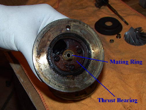
There is a punch hole located on the back of the Bearing Housing. In the attached photo it can be seen at the 12:00 position. The Seal Plate is removed by punching it out through the back of the B-H.
There was alot of gunk and scale on the Trust bearing. I don't think these Turbos had ever been rebuilt. The Mating Ring also showed signs of wear. The O-ring was totally pressed flat and was so toasted that it busted as I tried to extract it from it's groove.
The Thrust Bearing is attached with 3 Hex screws size .20. The new Hex screws supplied with the kit are size .15
Here's a photo....
Last edited by dgeesaman; 06-18-07 at 11:25 AM.