
Project: '99-spec style LED tail lights


I bought mine at ACE hardware for about $60 so you might want to check with them. They go for about $120 when not on sale:
http://www.acehardware.com/product/i...Id=45611397523
I also read scotty305's post and his fear of the viewing angle was mine also. They do make 5mm LEDs in wide angle versions:
http://www.radioshack.com/product/in...ductId=2102849
We'll see one you get this together. Good luck and keep us posted!
http://www.acehardware.com/product/i...Id=45611397523
I also read scotty305's post and his fear of the viewing angle was mine also. They do make 5mm LEDs in wide angle versions:
http://www.radioshack.com/product/in...ductId=2102849
We'll see one you get this together. Good luck and keep us posted!
Well, I been working on this also.. I've found a vendor who makes 60 LED circular board. Only issue is that they only have it in 2.5 inch and in order to do custom 3inch or bigger, it would cost thousands 
Here is a sample board..
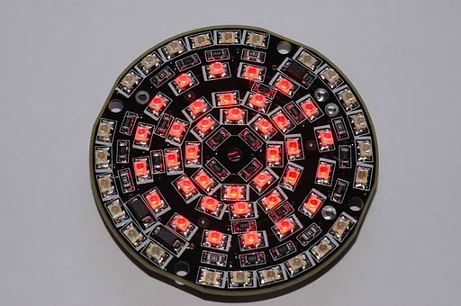
What I was going to do is use these and add additional ring outside of it (like the ones on the angel eye circular LEDs). Total to do this would be in range of about $500-600.
Here is a sample board..
What I was going to do is use these and add additional ring outside of it (like the ones on the angel eye circular LEDs). Total to do this would be in range of about $500-600.
Well, I been working on this also.. I've found a vendor who makes 60 LED circular board. Only issue is that they only have it in 2.5 inch and in order to do custom 3inch or bigger, it would cost thousands
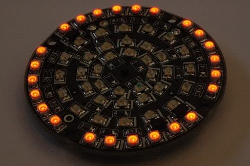
Here is a sample board.
What I was going to do is use these and add additional ring outside of it (like the ones on the angel eye circular LEDs). Total to do this would be in range of about $500-600.
Here is a sample board.
What I was going to do is use these and add additional ring outside of it (like the ones on the angel eye circular LEDs). Total to do this would be in range of about $500-600.
i'm sure something like that might be able to be used (if you could figure out how to make it bright enough), but it would be an entirely different style.
for $500-$600 i would want something that is closer to the OEM '99-Spec look, like i posted in the 1st post.
I bought mine at ACE hardware for about $60 so you might want to check with them. They go for about $120 when not on sale:
http://www.acehardware.com/product/i...Id=45611397523
I also read scotty305's post and his fear of the viewing angle was mine also. They do make 5mm LEDs in wide angle versions:
http://www.radioshack.com/product/in...ductId=2102849
We'll see one you get this together. Good luck and keep us posted!
http://www.acehardware.com/product/i...Id=45611397523
I also read scotty305's post and his fear of the viewing angle was mine also. They do make 5mm LEDs in wide angle versions:
http://www.radioshack.com/product/in...ductId=2102849
We'll see one you get this together. Good luck and keep us posted!
 i'll have to see if i can use Goodfella's over at IRP...RICHHHHHHH!!!!!!!!!!!!?????
yeah since i already ordered the style of LED that i posted before, i'll try those first. if they don't seem to be wide enough, ill swap them for some wider angle LED's.
keep in mind, since i'm planning on keeping the center area of the circle normal (clear/red reflector with a bulb behind it), brightness and viewing angle really shouldn't be an issue (hopefully!)
Regarding what Herblenny posted, circuit mounted LEDs usually outperform significantly what you are using so don't discount those if needed. I think the narrow versus wide angle is going to be an issue as you'll need to see these from wide angles regardless of the center section. You can always buy a few of the wide angle ones from Radio Shack to compare/contrast.
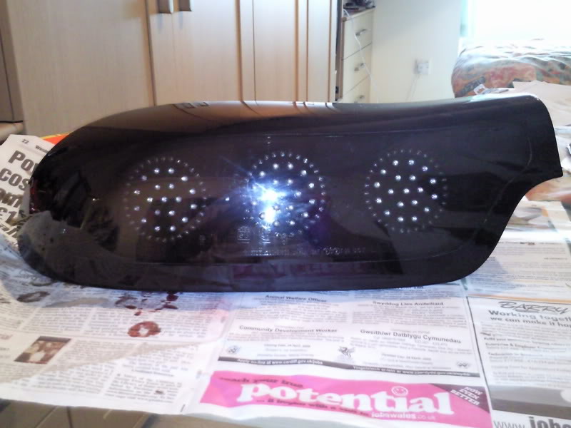
Also, to hide the PCB, can you paint the top of the board black after you drill the holes? Would this screw it up or not matter?
And what's with no drill press in the apartment? Come on, there are some things that are important in life and this is one of them. Your GF should embrace the moment and get with it! As you are in NY City, tell here it is "performance art" and charge a bunch of money to have people watch you drill the holes
Regarding what Herblenny posted, circuit mounted LEDs usually outperform significantly what you are using so don't discount those if needed. I think the narrow versus wide angle is going to be an issue as you'll need to see these from wide angles regardless of the center section. You can always buy a few of the wide angle ones from Radio Shack to compare/contrast.
Also, to hide the PCB, can you paint the top of the board black after you drill the holes? Would this screw it up or not matter?
And what's with no drill press in the apartment? Come on, there are some things that are important in life and this is one of them. Your GF should embrace the moment and get with it! As you are in NY City, tell here it is "performance art" and charge a bunch of money to have people watch you drill the holes
i have a few options on PCB color (black is an option) if i order some professionally made units. i figured that matching the lens colors (red & orange) would be best for "hiding" the PCB's behind the lenses (so you don't see the shape of the PCB.
really? hmm i was not aware. i was assume that based off of what i've worked with in the past. when i was looking for LED's in bulk. i could only find SMD LED's up to 800mcd. these through-hole LED's i plan on using are rated at 5000mcd...
i have a few options on PCB color (black is an option) if i order some professionally made units. i figured that matching the lens colors (red & orange) would be best for "hiding" the PCB's behind the lenses (so you don't see the shape of the PCB.
i have a few options on PCB color (black is an option) if i order some professionally made units. i figured that matching the lens colors (red & orange) would be best for "hiding" the PCB's behind the lenses (so you don't see the shape of the PCB.
http://catalog.osram-os.com/catalogu...00028b00010023
They go up to 40,000 or so mcd and much higher. A lot of the units are rated in 50 and above "lumens" which is substantially brighter. I know of these because I was going to use them in my Audi style LED project so I order a few of the 50 lumen golden dragon ones and they were so bright they would literally blind you. Much too bright for this application.
5,000mcd is pretty good also thought so we'll see (pun intended). Finally, OSRAM also sells 5mm LEDs in varying levels of mcd:
http://catalog.osram-os.com/catalogu...0002db00010023

that guy was mounting the LED's behind the colored inserts, iirc. also, he didn't do the turn signals.
just to clarify:
i never said that this project hasn't been done before (pardon the double-negative...), so i hope no one has taken it that way.
this project is about doing it a different way with a specific look.
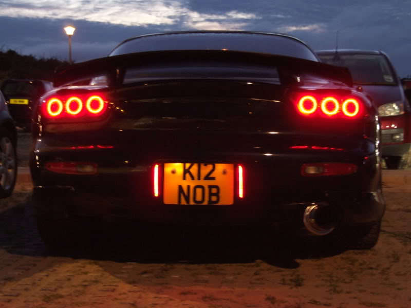
i really like how this photo looks, but i still want the center to "glow" (but not be super bright like the outer ring!).
Been talking to my colleague about this, looks like he is willing to help me make a set
He has done a lot of led displays and programmable light units before, could be good
Will be interesting to see how yours goes, I will be following this thread.
He has done a lot of led displays and programmable light units before, could be good
Will be interesting to see how yours goes, I will be following this thread.
i really like how this photo looks, but i still want the center to "glow" (but not be super bright like the outer ring!).

I really like where this is going,
*subscribed*
if somebody really want to shell out the cash for these.. be my guest,
http://www.rhdjapan.com/nagisa-nams-...p-lights-50236
I prefer what you guys are working on, but I also like the AF engineering ones..
Props for doing something different sir, I think if they were mine I might have made the turn outer most rings a tiny bit smaller, but either way, looks good (IMO)
J.
*subscribed*
if somebody really want to shell out the cash for these.. be my guest,
http://www.rhdjapan.com/nagisa-nams-...p-lights-50236
I prefer what you guys are working on, but I also like the AF engineering ones..

J.


Im still here, and I still have my FD, although I dont really offer the service anymore since Im kind of busy with my full time job.
A little background on the project: the leds used are 4 pin "spider" style and are carried on custom pcbs mounted behind the colored lens. in general that type of led or the smt ones will greatly outperform the t1 3/4 package while being easier to fit. I didnt do the signals due to the problems with mounting the board at an angle behind the curved lens. you need the leds to point straight rearward which is not perpendicular to the pcb. and a flat board behind a curved lens will show an inconsisent appearance because some leds are farther away from the diffusing lens than others.
I wanted to use a light pipe similar to how the 5 series bmws are but I wasnt able to get the desired brightness.
and regarding your design, you will need to run the leds in parrallel series groups with current limiting resistors. I dont think your current layout will work unless you have a huge current regulator on a different board. and with the small hole in the center of the board you will be losing most of the output of the center bulb when it hits the back of the pcb. just some considerations...
i remember seeing that YEARS ago, but i wasn't sure if the service was still offered. that website hasn't been updated since 2005...and i think that guy sold/trade his FD for a 350Z (i could be wrong)...
that guy was mounting the LED's behind the colored inserts, iirc. also, he didn't do the turn signals.
just to clarify:
i never said that this project hasn't been done before (pardon the double-negative...), so i hope no one has taken it that way.
this project is about doing it a different way with a specific look.
i really like how this photo looks, but i still want the center to "glow" (but not be super bright like the outer ring!).
Im still here, and I still have my FD, although I dont really offer the service anymore since Im kind of busy with my full time job.
A little background on the project: the leds used are 4 pin "spider" style and are carried on custom pcbs mounted behind the colored lens. in general that type of led or the smt ones will greatly outperform the t1 3/4 package while being easier to fit. I didnt do the signals due to the problems with mounting the board at an angle behind the curved lens. you need the leds to point straight rearward which is not perpendicular to the pcb. and a flat board behind a curved lens will show an inconsisent appearance because some leds are farther away from the diffusing lens than others.
I wanted to use a light pipe similar to how the 5 series bmws are but I wasnt able to get the desired brightness.
and regarding your design, you will need to run the leds in parrallel series groups with current limiting resistors. I dont think your current layout will work unless you have a huge current regulator on a different board. and with the small hole in the center of the board you will be losing most of the output of the center bulb when it hits the back of the pcb. just some considerations...
A little background on the project: the leds used are 4 pin "spider" style and are carried on custom pcbs mounted behind the colored lens. in general that type of led or the smt ones will greatly outperform the t1 3/4 package while being easier to fit. I didnt do the signals due to the problems with mounting the board at an angle behind the curved lens. you need the leds to point straight rearward which is not perpendicular to the pcb. and a flat board behind a curved lens will show an inconsisent appearance because some leds are farther away from the diffusing lens than others.
I wanted to use a light pipe similar to how the 5 series bmws are but I wasnt able to get the desired brightness.
and regarding your design, you will need to run the leds in parrallel series groups with current limiting resistors. I dont think your current layout will work unless you have a huge current regulator on a different board. and with the small hole in the center of the board you will be losing most of the output of the center bulb when it hits the back of the pcb. just some considerations...
thanks for the info! your project was definitely an inspiration.yeah i actually have modified the design since this thread first started (2 days ago?) so i'm looking to do it a little differently now.
yes i know the pcb will block some of the light form the bulb - i want it to do that. i want the center area to be slightly dimmer than the other ring. i think this will give the best effect.
i did some more calculations on the wiring/resistor setup i would need to use, so that is going to be changed as well.
anyway i was bored (since i'm still waiting for all my parts to come) so i started playing around in google sketchup. here's what i came up with:
awesome!!! good to hear. thanks for the info! your project was definitely an inspiration.
yeah i actually have modified the design since this thread first started (2 days ago?) so i'm looking to do it a little differently now.
yes i know the pcb will block some of the light form the bulb - i want it to do that. i want the center area to be slightly dimmer than the other ring. i think this will give the best effect.
i did some more calculations on the wiring/resistor setup i would need to use, so that is going to be changed as well.
anyway i was bored (since i'm still waiting for all my parts to come) so i started playing around in google sketchup. here's what i came up with:
thanks for the info! your project was definitely an inspiration.yeah i actually have modified the design since this thread first started (2 days ago?) so i'm looking to do it a little differently now.
yes i know the pcb will block some of the light form the bulb - i want it to do that. i want the center area to be slightly dimmer than the other ring. i think this will give the best effect.
i did some more calculations on the wiring/resistor setup i would need to use, so that is going to be changed as well.
anyway i was bored (since i'm still waiting for all my parts to come) so i started playing around in google sketchup. here's what i came up with:
"in general that type of led or the smt ones will greatly outperform the t1 3/4 package while being easier to fit"
Take a serious look at the OSRAM product info I posted. I've also spent a lot of time on the phone with them and they are pretty willing to help in identifying the proper SMT LEDs for your application.
^yeah i was looking into that david. i'm gonna give them a call this afternoon, or maybe drop an email instead.
we'll see what they say...
EDIT:
while browsing their site, i found this pdf.
they recommend using one of the following models for RCLs (rear combination lamps):
TOPLED
Power-TOPLED
Advanced Power-TOPLED
Dragon
i'll ask them about those models and give them some info on the specific application
we'll see what they say...
EDIT:
while browsing their site, i found this pdf.
they recommend using one of the following models for RCLs (rear combination lamps):
TOPLED
Power-TOPLED
Advanced Power-TOPLED
Dragon
i'll ask them about those models and give them some info on the specific application
Tom,
I like the idea a lot and this is the only proposal for LED tails that I personally have liked the look of. I like how you are wanting to keep the "stock" styling, regarding when the brake is applied and filling out the circle of the outline of the light. Let me know if you need any help and I am sure Rich would lend a hand as well
Good luck and I am really looking forward to seeing the finished product.
^yeah i was looking into that david. i'm gonna give them a call this afternoon, or maybe drop an email instead.
we'll see what they say...
EDIT:
while browsing their site, i found this pdf.
they recommend using one of the following models for RCLs (rear combination lamps):
TOPLED
Power-TOPLED
Advanced Power-TOPLED
Dragon
i'll ask them about those models and give them some info on the specific application
we'll see what they say...
EDIT:
while browsing their site, i found this pdf.
they recommend using one of the following models for RCLs (rear combination lamps):
TOPLED
Power-TOPLED
Advanced Power-TOPLED
Dragon
i'll ask them about those models and give them some info on the specific application
If I hadn't blown up my test units I would send them to you. I do have a kit that has a bunch of the "optics" lenses in it if you'd like that for testing. Here is a good site for ordering OSRAM units as well as competitor SMT LEDs:
http://ledsupply.com/led-catalog.php
You don't need the high powered ones listed that cost $5 - 10 per unit as these will be way too bright and costly but I know OSRAM and the other vendors listed at the top of the page sell lesser powered units at a more reasonable cost.
you should look up the output of the stock incandescent bulbs and aim for something around there. dont forget to take into account the red filter blocking some output. that will give you an idea of how many leds and what brightness you need. for mine i used 208 lumileds superflux which are rated 3.8lm each for a total of 790lm when the brakes are applied. this is kind of a lot and it borders on being too bright.
you guys are all doing it wrong
http://www.youtube.com/watch?v=GvzK1niudGE
http://www.youtube.com/watch?v=GvzK1niudGE

