
A lot harder putting it back together: RX7 Trivia Time!


A lot harder putting it back together: RX7 Trivia Time!
So I tore my engine out of the car and got the motor rebuilt and I'm in the middle of putting it all together. So far so good. Now comes the wiring harness. I have everything hooked up but the following, lets see if anyone can help me find where these connect!
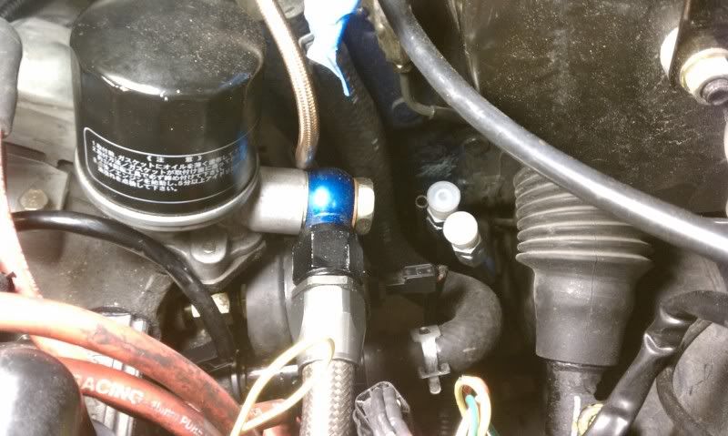
First and foremost is the fuel hardlines. The far left (without an adapter) is vented, but I need to know which one is the feed and which one is the return. Here is the diagram from what we see in the picture.
X Vent
X ????
X ????
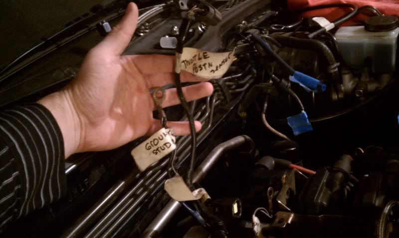
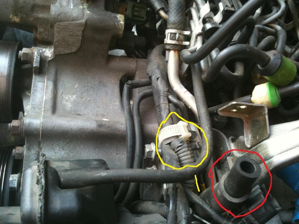
Next are these three wires. Obviously the ground I know I can ground that anywhere so no problem there. At the very top we have throttle position sensor, which will go on my throttle body when I have it on. No problem there. But the bottom one labeled "air temp". What area does that go to?
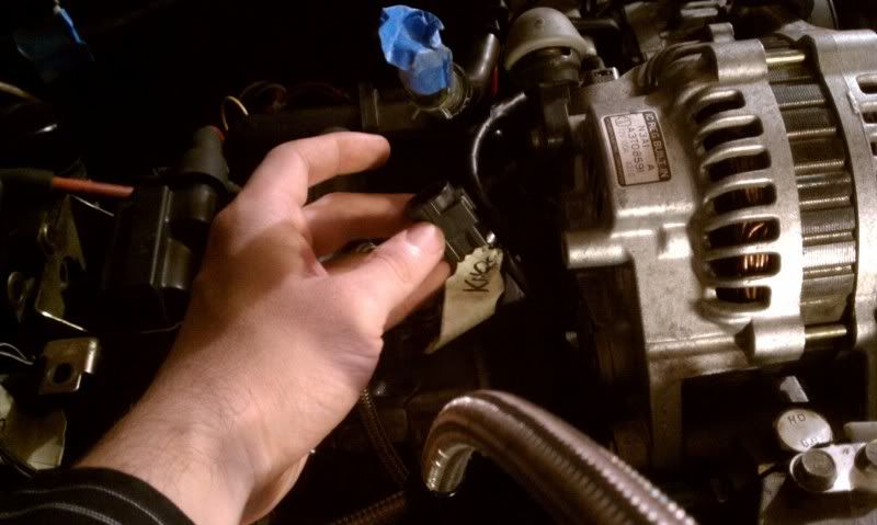
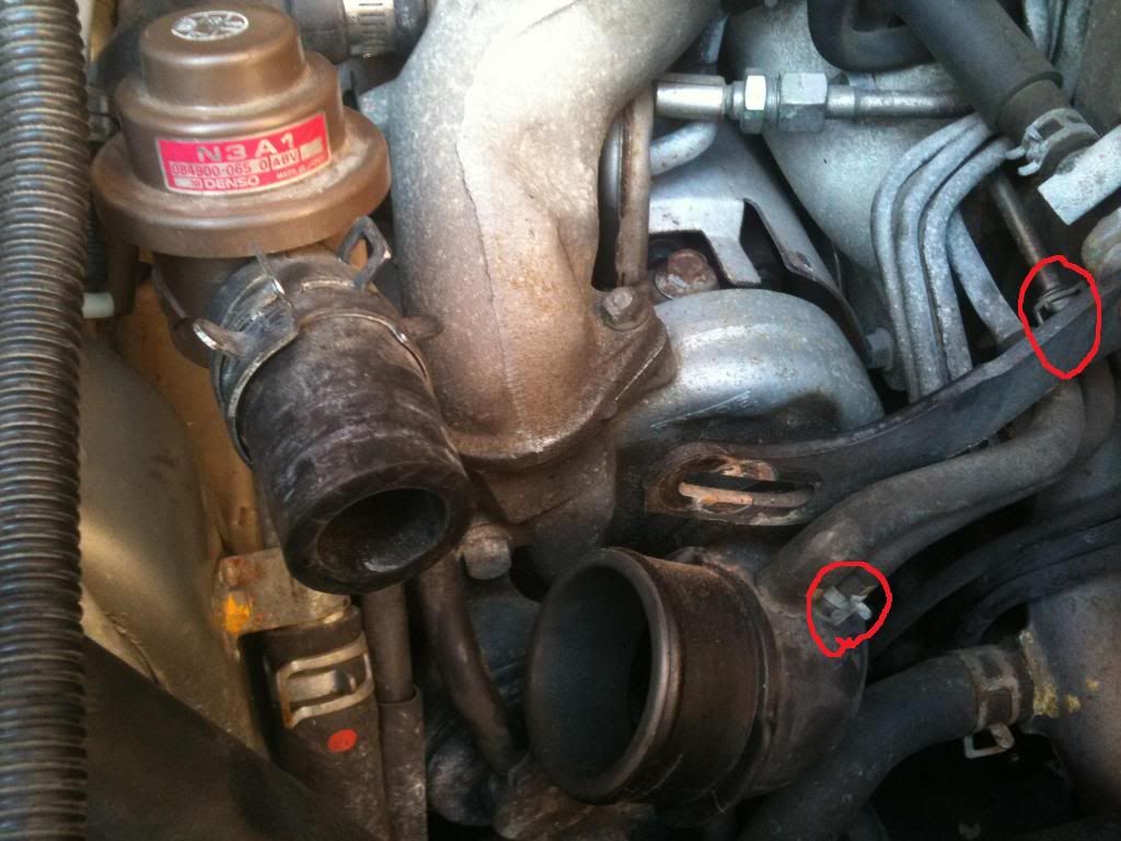
Next is the knock sensor. It looks like it should be near the front of the engine, but I cannot find any connection in that area that it would connect to.
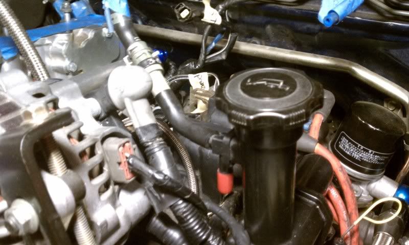
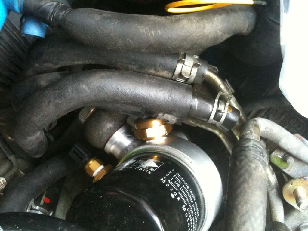
Last but not least was this thread I read about the oil filler neck and those two nipples. As you can see, the bottom one is blocked off (red nipple) and then the line coming off of it usually goes into the UIM. I read a thread though saying that it shouldn't be blocked off. Don't know if anyone else read this, but I have no idea what to do for these or if it will even affect me.
P.S. I don't know if this matters but my LIM and UIM have block off plates and the cars harness was modified for single turbo.
Thanks!
First and foremost is the fuel hardlines. The far left (without an adapter) is vented, but I need to know which one is the feed and which one is the return. Here is the diagram from what we see in the picture.
X Vent
X ????
X ????
Next are these three wires. Obviously the ground I know I can ground that anywhere so no problem there. At the very top we have throttle position sensor, which will go on my throttle body when I have it on. No problem there. But the bottom one labeled "air temp". What area does that go to?
Next is the knock sensor. It looks like it should be near the front of the engine, but I cannot find any connection in that area that it would connect to.
Last but not least was this thread I read about the oil filler neck and those two nipples. As you can see, the bottom one is blocked off (red nipple) and then the line coming off of it usually goes into the UIM. I read a thread though saying that it shouldn't be blocked off. Don't know if anyone else read this, but I have no idea what to do for these or if it will even affect me.
P.S. I don't know if this matters but my LIM and UIM have block off plates and the cars harness was modified for single turbo.
Thanks!

Fuel lines you could find with a little searching, I can't remember off the top of my head.
"air temp" should have a brown wire, and it should connect to your AIT sensor on the bottom of your UIM.
The knock plug is fine behind the alternator. The knock sensor has a long single harness that reaches it.
I have my filler neck vented.
Hope that helps.
"air temp" should have a brown wire, and it should connect to your AIT sensor on the bottom of your UIM.
The knock plug is fine behind the alternator. The knock sensor has a long single harness that reaches it.
I have my filler neck vented.
Hope that helps.


The knock sensor is threaded into the front rotor housing, above the front trailing (top) spark plug. It will have one wire connected to it with a plug at the end... this wire goes up the rotor housing (toward the center of the engine bay) to reach that plug. The knock sensor plug will meet the harness near one of the bolts for the oil filler neck.
On an OEM setup, the oil filler neck nipple that points down gets vented to the primary turbo intake. The primary intake may pull a slight vacuum (very very slight). If nothing else this gives oil and/or vapor a path through the engine and eventually the cat converter... I think the goal of this sort of design would be to vent the 'crankcase' but not pollute.
I agree with the other comments above... the AIT sensor is on the underside of the UIM... look for the small plastic sensor connector in one of the primary runners near the rear of the UIM.
The factory service manual and wiring manual has some decent diagrams showing the locations of most components and connectors.
So, I took a look at my engine and there is nothing right above the plug as far as a connection. When you say threaded into the front rotor housing, is there also one in the rear housing? I see two holes right above both the top spark plugs for my front and rear rotor housings but there is nothing there, just threaded holes.
Trending Topics
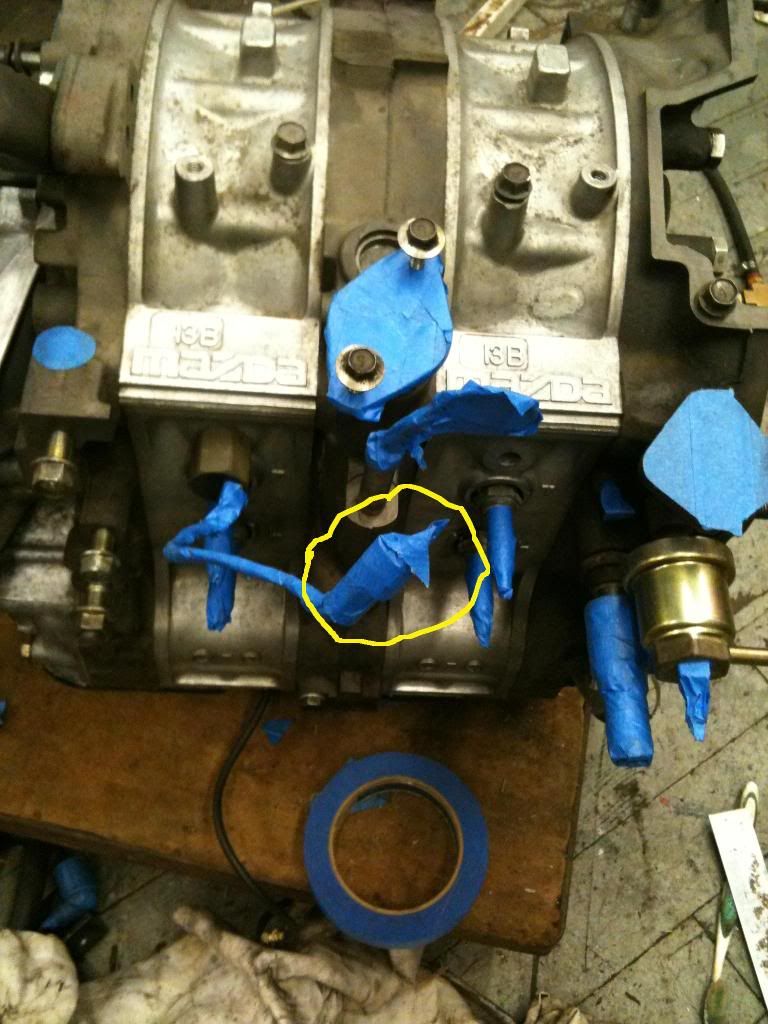
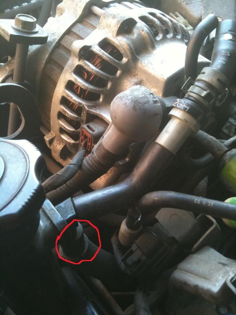

the knock sensor is usefull but not necessary, in post 9 in the rear housing directly above the spark plug there's what looks like a large nut attached, that's the knock sensor, unscrew it and it comes out, there's a hole for it in the front housing too that you can see that is unused.
edit: I guess he circled the connector for the knock sensor so you can kind of follow the tape
edit: I guess he circled the connector for the knock sensor so you can kind of follow the tape
Awesome, I actually found my knock sensor in the pile of parts so the wiring harness is all set. For fueling, from what I see, it goes
VENT
RETURN
FEED
Anyone confirm this?
Also, for tranny fluid, I don't know if we drained all of it, so is it ok for me to put in the old tranny fluid just to get the car started and running? Then do a complete swap to new tranny fluid. We have no idea what the original fluid brand was/is so this is why we want to mitigate the risk of mixing fluid.

Full Member
Joined: Apr 2010
Posts: 74
Likes: 0
From: RI
Awesome, I actually found my knock sensor in the pile of parts so the wiring harness is all set. For fueling, from what I see, it goes
VENT
RETURN
FEED
Anyone confirm this?
Also, for tranny fluid, I don't know if we drained all of it, so is it ok for me to put in the old tranny fluid just to get the car started and running? Then do a complete swap to new tranny fluid. We have no idea what the original fluid brand was/is so this is why we want to mitigate the risk of mixing fluid.
VENT
RETURN
FEED
Anyone confirm this?
Also, for tranny fluid, I don't know if we drained all of it, so is it ok for me to put in the old tranny fluid just to get the car started and running? Then do a complete swap to new tranny fluid. We have no idea what the original fluid brand was/is so this is why we want to mitigate the risk of mixing fluid.
On the fluid I would just unbolt the 2 drain plugs let as much out and put in new fluid.

Awesome, I actually found my knock sensor in the pile of parts so the wiring harness is all set. For fueling, from what I see, it goes
VENT
RETURN
FEED
Anyone confirm this?
Also, for tranny fluid, I don't know if we drained all of it, so is it ok for me to put in the old tranny fluid just to get the car started and running? Then do a complete swap to new tranny fluid. We have no idea what the original fluid brand was/is so this is why we want to mitigate the risk of mixing fluid.
VENT
RETURN
FEED
Anyone confirm this?
Also, for tranny fluid, I don't know if we drained all of it, so is it ok for me to put in the old tranny fluid just to get the car started and running? Then do a complete swap to new tranny fluid. We have no idea what the original fluid brand was/is so this is why we want to mitigate the risk of mixing fluid.
Looking at the firewall, from left to right it's vent, return, feed. You will notice the feed line has more of an angle to it. Also, if you shine a light in the rear line, you will see there is debris from the years of sitting... It is clearly the vent. The return sits in the middle.
GL OP
just turn the key to on position and fuel will come out of the feed (just turn the key on then back off quickly) showing you what line is the feed. The one that stays dry will be the return
Alright, thanks guys.
Last question. For my fuel system, I received new injector clips. I purchased ID725 and ID2000 injectors and I had a few questions. Do those injector clips NEED to be wired in? I wired in the primary clips but when I went to take a look at the secondary clips, they clipped directly onto the secondary injectors and I didn't replace those clips with the clips provided with my injectors.
These are high impedance injectors so there is no need for resistors or an FDO box etc.
if they work with the stock clips then don't worry about replacing those with the ones from ID since you don't need an driver or resistors, I'm curious to hear how it runs with that injector setup as that's my plan too, cept I'll probably be running e85

The more I read about the ID's the more I like em, but having a pretty tame car I just haven't been able to justify putting them in the car.
I am really interested in how it progresses for you so let us know. Are you running a PFC or another EMS?
I am really interested in how it progresses for you so let us know. Are you running a PFC or another EMS?
I will be running a PFC as my management. I will let you guys know how everything goes, hopefully good.
Also, are there any adjustments need to be made on the FPR before firing up the car?
Also, are there any adjustments need to be made on the FPR before firing up the car?
I just installed my fuel system for my 35R. Yes, that is correct for the lines if you are speaking of the hard lines on the firewall. I didn't pay much attention where they go to the stock setup on the block, as I installed aftermarket lines & rails.
Looking at the firewall, from left to right it's vent, return, feed. You will notice the feed line has more of an angle to it. Also, if you shine a light in the rear line, you will see there is debris from the years of sitting... It is clearly the vent. The return sits in the middle.
GL OP
Looking at the firewall, from left to right it's vent, return, feed. You will notice the feed line has more of an angle to it. Also, if you shine a light in the rear line, you will see there is debris from the years of sitting... It is clearly the vent. The return sits in the middle.
GL OP
Can someone look at this picture and please tell me what the problem is here?
So if you can't really tell since I used my camera phone, the secondary fuel rail fitting and the FPR fitting are right next to each other meaning I cannot get my hose to connect to the FPR.
The fitting coming from the bottom of the FPR is my return line and goes to my return hardline, but I cannot get the hose to connect since the fittings are basically running into each other.
Has anyone ran into this problem? Solution?