When you click on links to various merchants on this site and make a purchase, this can result in this site earning a commission. Affiliate programs and affiliations include, but are not limited to, the eBay Partner Network.
Well, only de-soldered the resistor and tested it; flashers work as they did before LED swap. I can't drive the car ATM, but surely Mazda wouldn't put the function and performance of the entire car solely on one resistor, so I'm going to assume everything is fine without installing the new one.
Did the mod and it didn't work. Redid it and still no go so sent it to Dale. He redid the mod and still no go. Brushed off the board and then resoldered several suspect joints. That did the trick.
I never messed with circuit board components before but it really wasn't too bad. I felt inspired to try and fix my hazard lights at the same time since they never worked. Narrowed it down to the circuit board itself, right behind the hazard button/ heater controls. Replaced that particular pathway with a wire since it had no resistors or caps inline, and good to go!
^Try simply removing the R1 resistor, then test for hyper-blinking. If your LED turn signals work normally at that point, consider leaving your newly snipped R1 resistor as-is; I.e., no replacement.
Last edited by Topolino; Jun 10, 2018 at 12:23 PM.
Turns out I had my tail light harnesses swapped. Apparently, the wiring is different and will make things go crazy if you mix them up. Everything is good to go now.
Somewhat related:
Are there any LEDs that can match regular bulbs light spread? I ahve yet to see a LED that give a 100% uniform light output. And with my level of OCD thats important
They are out there, you have to do some digging and research. LED bulbs are changing VERY fast so what is good today won't be available tomorrow or will be eclipsed.
There are some threads on bulb recommendations and bulb "styles". The super cheap Ebay bulbs are gonna let you down. Also, you need colored bulbs for the turn signals, brake lights, etc. - if you put a white bulb in the light output will be crap behind a red lens.
I can confirm that just removing the R1 resistor fixes the fast signal. I just completed this on my car and it resolved my fast signal problem with no other side effects.
Was just wondering if this works on the FC's cpu as well?
I'll find out soon enough, just did the LED tail light swap on my FC and need to correct the hyper-flashing turn signal issue. For the time being, I'm using my old bulbs for the turn signals and LEDs for everything else.
Originally Posted by DaleClark
Quite possibly, the CPU in the FC is similar and I can't see them doing a huge redesign of the flasher module. It would be worth a try.
Dale
Hey Dale, old post but do you recall how you figured out that R1 was the resistor to delete & substitute? Unfortunately the S5 FC schematic in the FSM (page Z-78) just shows the flasher unit as a black box within the CPU with 7 wires in/out of it. Kind of hard to reverse-engineer what's going on! From your pictures, the FD CPU flasher unit looks a lot like the FC unit, but I don't have a few spares laying around to experiment on.
Ok, so I took out the CPU/flasher unit from my S5 FC to take a peek. Comparing my pictures (see below)
with Dale's pictures in the 1st post, it would appear that these circuit boards are laid out the same. So, I'm feeling adventurous - First I'll de-solder the R1 resistor and leave it vacant. If that solves the hyper-flash LED turn signals, I'm done. Otherwise, next thing I'll try is soldering a 1M ohm resistor in R1's place
^Update - It works on an FC! Caveat - at least it works on an S5, you S4 guys will have to do some experimenting. All I did was desolder one of the R1 leads from the circuit board, tested it out and found that the flashers/turn signals flash at the same normal rate as before. No other ill effects from the change. Since I left R1 resistor on the board with just 1 of its leads soldered, I put some heat shrink over R1 to insulate the loose lead, put the flasher unit back inside the CPU and reinstalled it in my FC. BTW, I replaced every 1157, 1156 & 194 type exterior bulb with their LED equivalent, so there's no mixing with regular bulbs that might cause a false positive result here.
^There's more than one circuit board in that black CPU/flasher box - it appears that you're looking for the resistor on the wrong circuit board. The circuit board you're looking for should look a lot like the one my pictures in post #68.
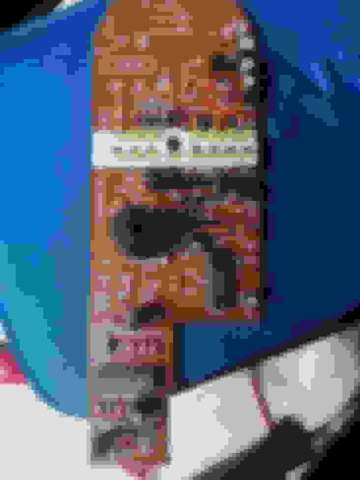
I made a stupid mistake, and because I was pushed for time didn't refer back to the guides online, so I actually removed the R1 resistor on the board shown in the pic above, not the smaller flasher unit 🤦🏻♂️
So, can anyone confirm the spec of the R1 resistor on the main board, or the colour bands, as I need to replace it. Just to be clear, it's the one circled in the pic below:
Any help would be very much appreciated, to save me from my stupidity!!
Resistors don't have polarity so they can be installed either way.
If you still have the one you removed, look at the color bands on it and look up a resistor color band guide, that will tell you the resistance.
Also I don't know if there is an electronics shop, stereo/TV repair place, etc. somewhere near you. You may be able to go show them the part and they may have one on hand to sell you for cheap. Those resistors typically are like a penny each, it would cost more in shipping to just get one.