
Just got my first 3rd gen, it has a few eletrical issues.


Thread Starter
Rotary Enthusiast
iTrader: (18)
Joined: May 2008
Posts: 1,150
Likes: 0
From: Texas BABY!
I tried searching for that user you mentioned above, chuckwestbrook , but i got nothing. Did you spell his name wrong?
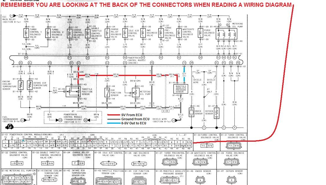
Anyone know which wire on the PFC is the 5v wire?
Anyone know which wire on the PFC is the 5v wire?

Thread Starter
Rotary Enthusiast
iTrader: (18)
Joined: May 2008
Posts: 1,150
Likes: 0
From: Texas BABY!
Thanks a lot! That helps a lot! now i can backprobe the 5v out and see what it shows, see if it is an ECU issue or wiring issue. gonna go check that out and report back.
Remember if there is a grounded or high resistence to ground in the wire, it will not read the correct voltage out of the PFC, so pull the pin out of the connector to check the true voltage out of the PFC
Thread Starter
Rotary Enthusiast
iTrader: (18)
Joined: May 2008
Posts: 1,150
Likes: 0
From: Texas BABY!
true, although i am getting some strange readings.
Does the PFC move the connectors order around from stock? the pins seem to be in the right places but the connectors them selves are in a differnt order.
But checking the pins you outlined, the 5v out and back seem to be right at least. The voltage matches on both ends of the wire. 5.2 volts going out and 3.5 volts coming back with the map connected, 4.2 volts on the signal wire if i disconnect the MAP.
The grounf wire i am not sure about though, i see about .3 volts on the ground wire at the ECU but at the map sensor i see about 1.3 volts. I checked the TPS ground wire (well i assume it was) and it came out to .3 volts as well so that pin you pointed ut may only go to the TPS? i know it does not match the color of the wire at the MAP.
I am totally lost here, no clue what all this means. Bad ground looks possible as i should see no voltage on the ground wire right?

Thread
Thread Starter
Forum
Replies
Last Post
rotor_veux
2nd Generation Specific (1986-1992)
3
Sep 28, 2015 09:25 PM