When you click on links to various merchants on this site and make a purchase, this can result in this site earning a commission. Affiliate programs and affiliations include, but are not limited to, the eBay Partner Network.
I think Alexdimen is right. I will put that theory to the test. The reason why is that, there are two circuit boards here the top and bottom. There are capacitors and resistors on the bottom board and IC, capacitors and more resistors on top. Maybe before installing the new capacitors make sure that the board is clean and contacts are good. Carbon, dirt and cold solder are one of the main problems in circuit boards. Good clean soldering would be the ideal cure for this. But again we will see. Wish me luck.
I think Alexdimen is right. I will put that theory to the test. The reason why is that, there are two circuit boards here the top and bottom. There are capacitors and resistors on the bottom board and IC, capacitors and more resistors on top. Maybe before installing the new capacitors make sure that the board is clean and contacts are good. Carbon, dirt and cold solder are one of the main problems in circuit boards. Good clean soldering would be the ideal cure for this. But again we will see. Wish me luck.
Any luck with that? Now that the weather has been cooling off, my ODO works less and less often!
I will see how road time impacts it but I had the same thing to a degree and resoldering on both sides of the new capacitor worked. I first soldered in a new capacitor backwards, flipped it and it was working fine. Once I built the gauge cluster assembly back up and installed it, it decided to stop working again. Once I pulled it apart and resoldered it getting both sides it worked again.
I will see how road time impacts it but I had the same thing to a degree and resoldering on both sides of the new capacitor worked. I first soldered in a new capacitor backwards, flipped it and it was working fine. Once I built the gauge cluster assembly back up and installed it, it decided to stop working again. Once I pulled it apart and resoldered it getting both sides it worked again.
I hope your fix sticks. I haven't had a chance to go back and re-solder mine a 4th (?) time, but will be doing so this summer.
My ODO worked again for several days through a HPDE at VIR after I had a solar charger hooked up to the battery. It has since blinked back out.
Without fail, leaving the car in the hot sun will make the ODO work. From working on an old FC, this is reminiscent of a cold solder joint somewhere.
I plan to go back in with a 50 watt iron and an ohm meter on a number of solder joints to solve this problem once and for all.
I'm not keen on buying a used unit which will just flake out again, especially after all the other work and fixes I have put into my gauge cluster.
Let me start off by saying: IT FINALLY WORKS! I never knew how much I missed those little orange numbers until they were gone.
Recap:
Replacing the capacitors and re-soldering other components like connector pins, diodes and resistors DID NOT fix my problem.
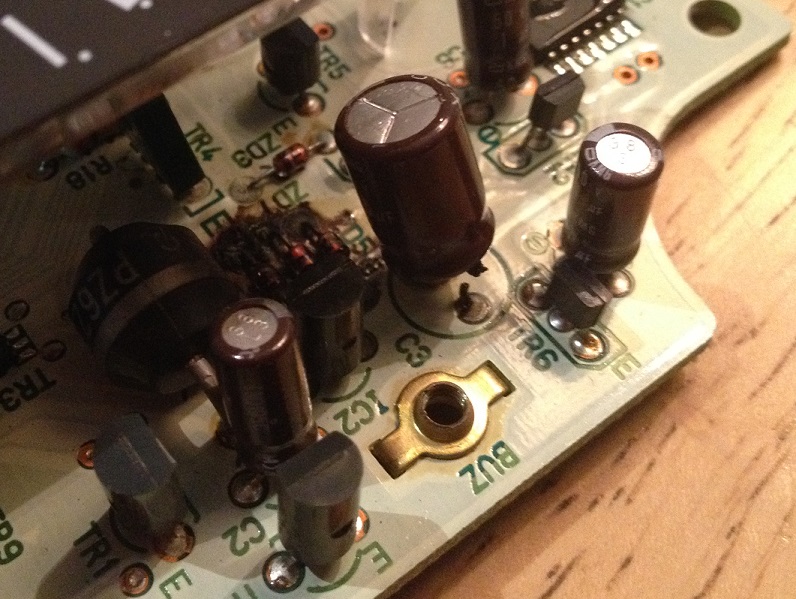
So, I took the cluster to Southern Electronics in Southside Richmond, VA. They had it for two and a half weeks, then call me to say that it cannot be fixed. I need a display driver and the part (OKI chip pictured) is no longer available. I suspect this isn't the case because not only is the display not working, but the cruise control is out too. They kept my car off the road for half a month for nothing. I was pissed.
Still, it got me thinking. I open up the ODO again and see that they didn't try to re-solder the display driver, but re-soldered nearly every other joint and replaced all the caps AGAIN. Reason being that the driver is under the display and a royal PITA to get to.
I was able to get the display out of the way enough to re-solder the chip underneath by first de-soldering all the pins on the row nearest the edge of the board with solder wick. You can never get it all out, so I melted each pin individually, then gently bowed the pin so it pulled out of the hole. Then, I melted out the plastic pins of the display holder going thru the board and removed the screw from the underside of the board. Prying the display off the board I was just barely able to get my iron in and drag it across the pins to re-solder. Then, checked my work with a magnifying glass like he says in the video, looking for bridged pins. FYI: you don't add extra solder, just flux.
For good measure, I did the same with the other surface mount chips... so I have to admit I am not really sure which joint was bad.
Sorry to bring up this topic. But does anyone maybe have an eletric diagram of the speedometer circuit board?
Thanks
Ya I would also like this. I am in the middle of trying to rebuild my board too. I am seeing that there are darlington transistors on this also ontop of non-darlington transistors, and not sure what to get as there are NPN and PNP types and many flavors of each type. I also would like to know the actual zener diode specs the boards use.
Well, I replaced the 6.3v 1000uF cap, and then the odo started working, then went back out within minutes, however my speedo and rpm gauge worked for the whole time I drove it last night. I come back out and start it this morning and no odo/rpm/speedo at all.. Guess I need to take it all back out and replace all the caps. I ordered a bunch of caps to try out that are all within as close to the specs as the originals I could find. They all match volts and uF, but some have different ohm/ripple rates, but all are 105c or higher temp operating range. See if this will fix the issue. I also had a friend tell me I should reseat and solder the odo to the board. I will see if that fixes it.
If the above doesn't work. I will try and replace all the diodes and transistors too I guess... lol
My odometer went out a few years ago one cold winter. Then my tach/speedo worked intermittently past few days and now it seems gone. (Just changed clutch, dont' know if that could be the cause)
I replaced the capacitors but these diodes seem to have black gunk all around them. Do diodes go bad? Do I need to replace them?
Diodes are pretty stable mechanically. They are a semiconductor so there isn't much that can go wrong/leak out, unlike a capacitor. They are susceptible to heat from what I hear... so I don't leave a soldering iron on the leads too long.
Just wanted to let you know when ordering the caps from digikey the 10 microfarad (P11250-ND)and the 1 microfarad capacitors (P10312-ND) are obsolete parts, went with P10316-ND (10 microfarad) and P14504-ND (1 microfarad). Just ordered a full set for the gauge, hopefully it will fix the non working odometer/speedometer.
Well I just got done attempting to fix mine. The 1000mF cap definitely was bad as the side was all burnt up and whatnot. Then I replaced all the ones with all the black crap around them. I didn't replace all of them though. I haven't started the car up yet but I turned it on enough to see if the ODO would work and it didn't. Looks like I'm going to pull it back apart and change them out and make sure everything is soldered well enough. Anyone else have any new updates/suggestions?
Thanks for this great write up. My odometer went out and then I started getting the occasional erratic tach and speedo readings and a check engine light stating the speed sensor was bad. Took the cluster all out, broke the hood, and changed all four cap types listed in the thread. Plugged it back in and odometer is back on and looking good. I ran the car for a short while and nothing bad, except my usual weird idle, but that's another issue I have yet to work on.
Again thanks for the write up and I hope my new caps and soldering job holds up.
This thread was EXCEPTIONALLY helpful in identifying my odometer blank out gripe. I lost the numerical display but could see the backlit illumination.
The tutorial is very helpful especially listing the capacitor part numbers from digi-key.
The 1,000uF capacitor was the only solid state component that released the magic smoke. I confirmed it after removing the speedometer from the circuit board. It didn't take too long to suck out the solder, remove the bad cap, install a new one, then reflow solder to the joints.
I did note that the solder runs along the odometer display appeared burned. After a closer inspection under a microscope, the solder cups were not deformed or damaged. However, it was 22yrs of old flux! A liberal use of alcohol and acid brush removed that old nasty flux in minutes.
Here are two photos showing first, the bad capacitor, then the crusty flux on the odometer cups. No "after" photos were taken.
Install and testing starts tomorrow because of plastic surround repairs were required. The glue used, Loctite GO2 Glue, requires 24hrs of cure time.
The 1,000uF capacitor leakage within the red circle.
Here is 22yrs of old flux on the solder cups of the odometer display.
After "fixing" my odometer its still not right.
1. speedo is off, could that be from installing new caps. In my experience changing old caps with new will change values in circuit. Current circuit operating specs will be with old cap value, so with new caps, circuit will need to be calibrated again.
2. Odometer will read when key is turned to ACC and ON, but once engine starts, it no longer shows. Have to turn off completely and then turn back to ACC/ON and it will read again. Any one else seen that and had a good point to start or am I just going to have to start checking wiring?
Thanks for the advice/help
Did you desolder the speedometer from the board then inspect all capacitors? When you installed the new caps, did you ensure the polarity matched from the old cap to new cap? If cap polarities are mismatched then you could have a variety of gremlins! You may also have a loose ground or the flex print may not seat against the instrument cluster connectors well. Double check the 3 screws are tightened well on the back of the cluster because they control +12v, GND, and TACH signals to the cluster.
my 1000uF cap was hanging by a leg.. and the diodes next to it do not look to good either, looks like the board material has deteriorated around the legs. going to replace the cap and solder the diodes, hope it works
im going with a 16V cap, maybe help it from blowing up next time
my 1000uF cap was hanging by a leg.. and the diodes next to it do not look to good either, looks like the board material has deteriorated around the legs. going to replace the cap and solder the diodes, hope it works
im going with a 16V cap, maybe help it from blowing up next time
Good to see that you found the problem.
I strongly encourage you to replace it with the specific cap. By using the higher rated cap, it could cause electrical gremlins in your instrument cluster. Maybe not now but soon! Not to mention that it's only rated for 6.3V
Use the Panasonic 1,000uF cap from Digi-Key under PN: P10199-ND (or other solid state retailer). In earlier posts (Pg 2), you will see the original PN was superseded by this one. The Panasonic cap will outlive the car when replaced correctly.
One more note, this is an electrolytic capacitor so make sure that you note the polarity of the leads. The Panasonic cap has a gold stripe that indicates the negative (-) lead. That lead must be closest to the diodes. I don't know your electrical experience so excuse me if I may insult your skills.
Do let the board know how your repairs go! I wish you the best of luck.


 Wish me luck.