When you click on links to various merchants on this site and make a purchase, this can result in this site earning a commission. Affiliate programs and affiliations include, but are not limited to, the eBay Partner Network.
Thanks for the photo upload guide. Took a second try when I did not hit the "upload" icon after it seemed it had been uploaded to somewhere already. Then it worked.
New info regarding previous post: AutoECU.com said on phone they "do not have the equipment to work on and test the instrument panel on a 93 Mazda Rx7" though they do some other car instrument panels.
Last edited by rousu; 09-24-20 at 04:22 PM.
Reason: new info
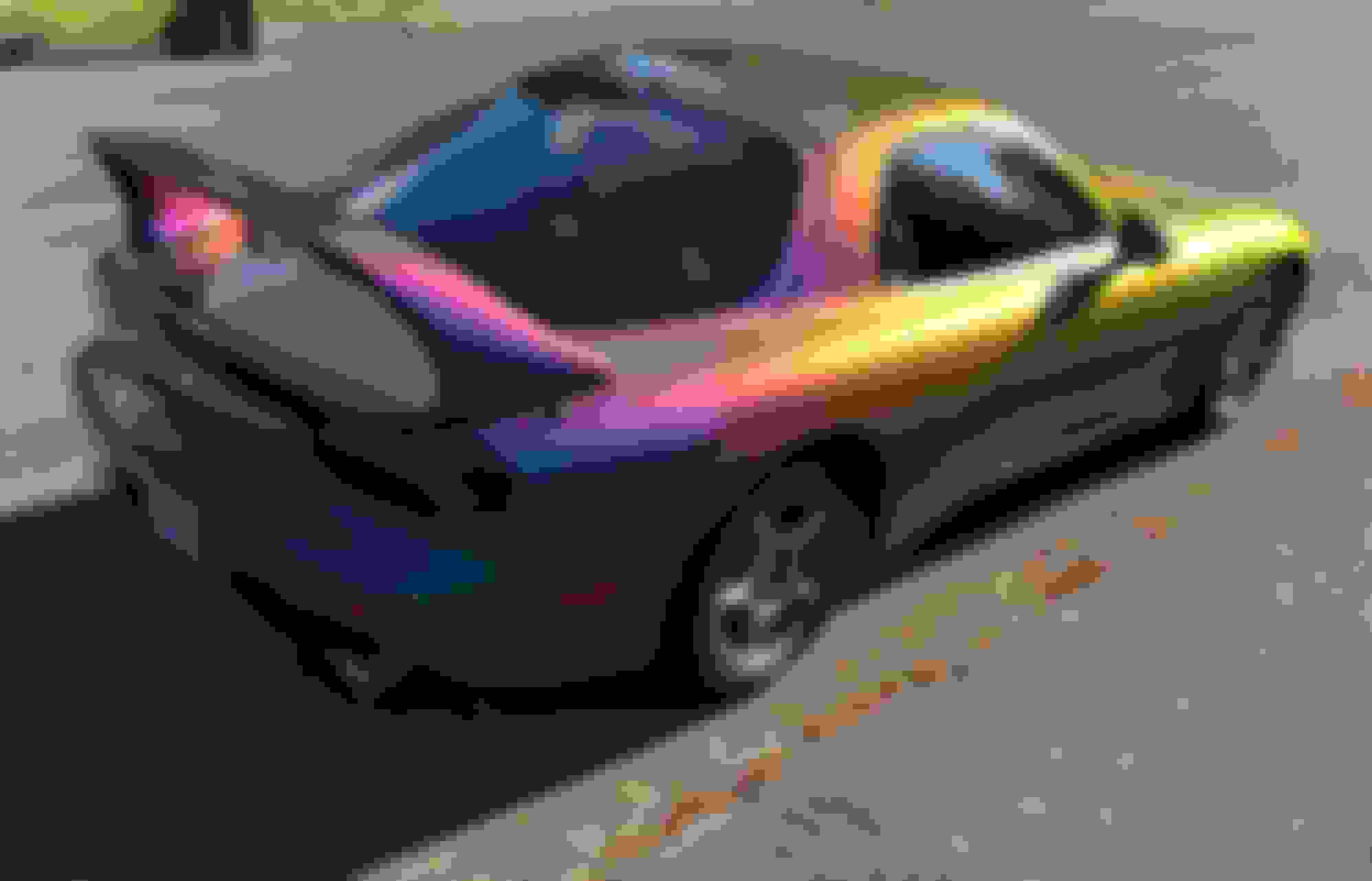
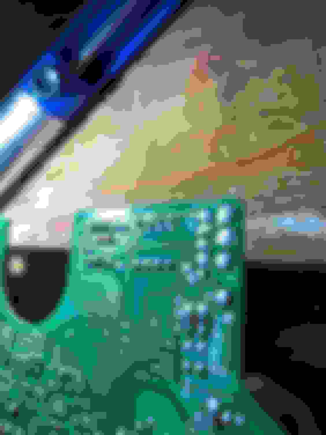
Good to hear that it helped. That's an interesting paint job for your car. What's your plan for the instrument cluster? Will you pull it then send it off for repair? Before you send it off, make sure to take some pics then post here. You should be able to capture most of the components under the speedo face without the need to desolder it (face). It helps to shine a flashlight at certain spots to remove the shadow effects. Just be sure to take close-up shots, a lot of detail is hidden when looking at the entire board. It will not be necessary to take photos of the backside of the board, unless there is a burn mark that goes through top to bottom.
The key areas to focus are the top 1/3 of the board, especially around capacitors C2, C3, C4, C6, and capacitors around the stepper motor.
I appreciate you sharing the video but would you please stay on topic for the speedo repair? The short video would make an interesting stand-alone thread in the main FD section!
I just noticed your update about AutoECU. I'm sorry to hear that didn't pan out for you. You could contact DNA Speedometers in FL. They have previously repaired FD speedos for other members. I cannot offer personal experience about them though.
Please keep in mind, this thread is about DIY repairs to the speedometer and less about repair service recommendations. When you are ready to post pics of your speedo board then I'd be happy to offer some personal observations.
I messed around with this repair before and the only fix that has stuck was replacing all capacitors on the speedo board. It seems simple but the proper tools are what matters here. I don't think a soldering iron and some solder suckers will cut it.
I believe I've posted before about this here but it's likely lost in the stack of comments. I have a guy local to me, NEPA area, that repairs professional sound equipment at home. He will do this odometer repair for under $100. He replaced all the capacitors on my board 2+ years ago and I haven't had an issue since. If anyone wants to send theirs out, PM me and I can coordinate the repair. Alternatively, ask your local guitar/music/recording store, they will most likely have someone that repairs their equipment.
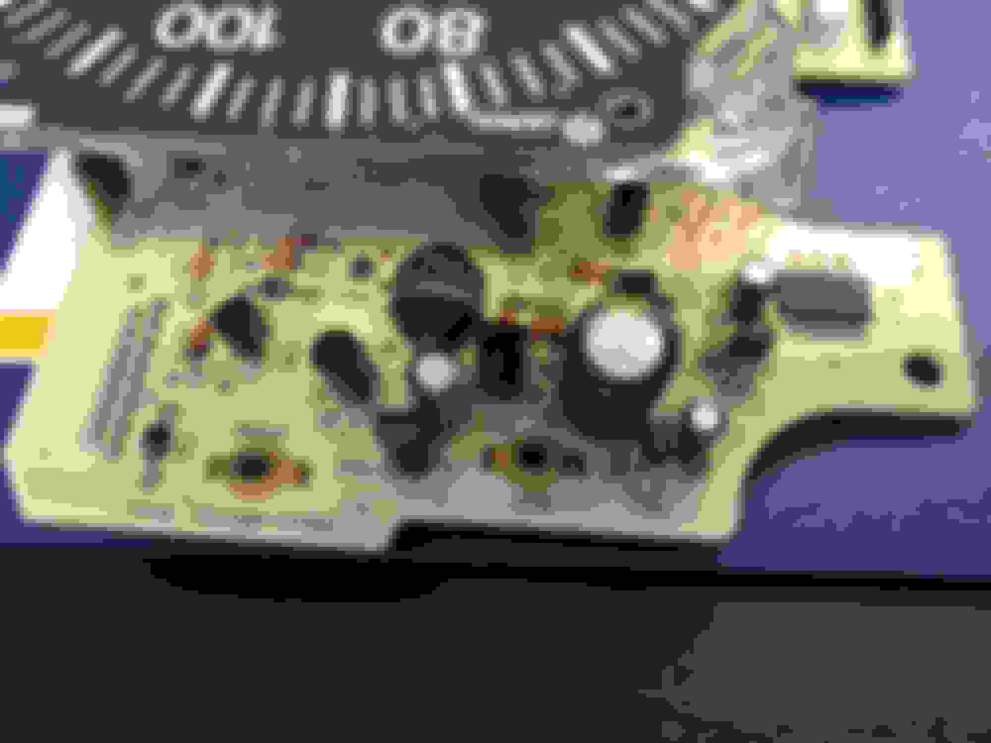
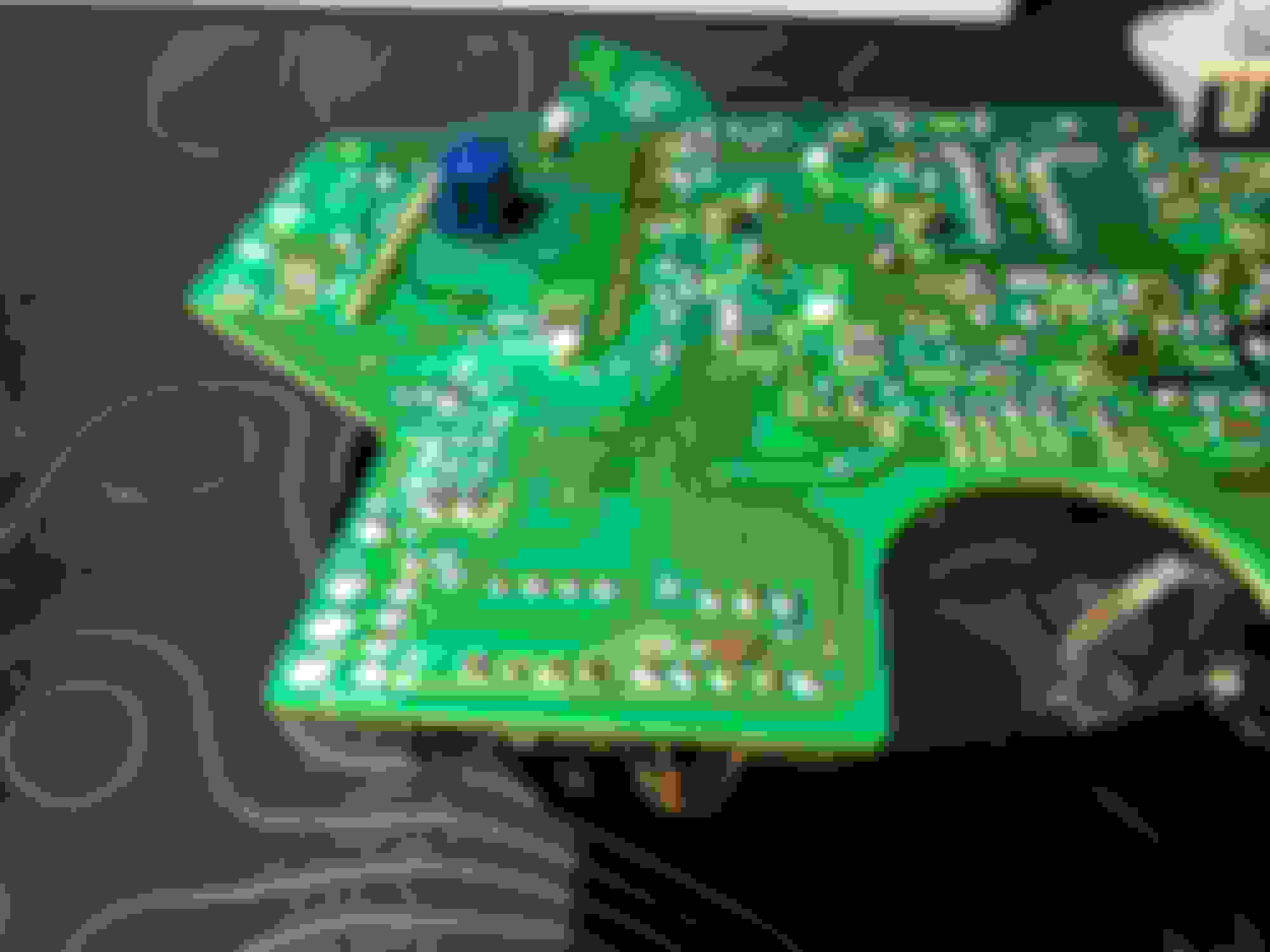
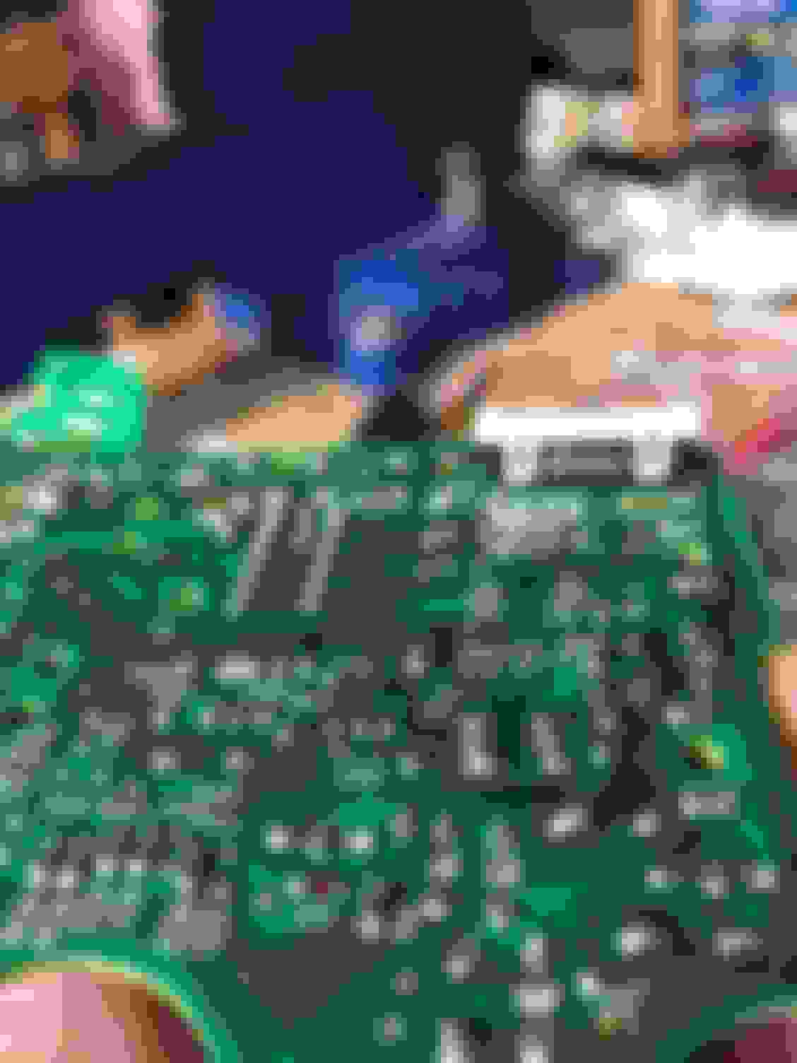
Looks like C3 pretty well crapitated on TR7 and DA1, which are directly below C3 when installed in the car. Is DA1 still one of the difficult replacements? Will be able to see any damage better after it is cleaned up.
(My symptoms: unreadable odo, auto-tranny HOLD light and CHECK engine light flashing. )
Thanks for sharing the one photo. I am not surprised to see that layer of mung on the board. All that char is baked on electrolyte. It should clean off with isopropyl alcohol and a toothbrush/q-tips. It may take several attempts to clean it properly.
If you decide to clean it up, be careful not to manipulate those components. You may want to check for broken leads to those components. After cleaning the board then tilt it at various angles to see how the leads connect to the body of each component. I would not be surprised to see a few leads nearly gone from the corrosive effect of the electrolyte. There are plenty of examples on my other FD speedo troubleshooting thread.
If you can take some close-up angled shots of the components then I may further advise on which components should be replaced in addition to all electrolytic capacitors.
How does the rest of the board look?
One of the diode arrays should be easily procured. But you want to check with my latest post from the Speedo parts list thread. I don't recall if DA1 or DA2 can still be sourced.
Success !!!
All capacitors replaced, and board cleaned up with isopropyl alcohol.
Drove it home and
odometer working with the real milage
trip odometer working
The auto tranny HOLD light did not light up randomly
The HOLD function seemed to work right on one try
The CHECK ENGINE light did not light up at high revs
Wahoo!!
Seems everybody should do this to preclude acid damage from leaky capacitors, which could be these symptoms or worse.
I found an electronics technician, a David Su, who seemed technically capable and willing and had all the right equipment. I had my usual mechanic pull the cluster and remove the board with the speedometer. David replaced all or most all of the capacitors on the board, removed two transistors that had been crudded up and tested them and verified ok, then remounted them. Cleaned up the board flux and leakage with alcohol.
I was very happy to see the HOLD function and the CHECK ENGINE warning problems go away from fixing the speedo board; that was my hope, but I thought it was low probability. The thread shows some people had the same problems, but it was not clear that fixing the board had cleared those two problems.
I took a couple "after" photos, I will try to pull them off my cell phone.
I am happy to hear that replacing the bad components on your speedo board solved the problem. I had greater faith that the board would solve both problems given the fault codes, discoveries in the troubleshooting matrix, and the physical damage to the board. Thanks again for providing the feedback and posting the "after" photos. Enjoy driving your prismatic-colored FD with a fully functioning tach and speedo!
@Gen2n3
Thank you very much for the information on this matter. I've gone through Commercial Speedo in Sac, CA as well as Circuit Board Medics, both of whom have rejected working on the FD gauge clusters given how finnicky they can be to fix.
Having exhausted shop options, I'm tackling my own cluster, which exhibited symptoms after I replaced did a LED replacement on the cluster (regret this so much) while doing a rebuild on the 13REW.
Issues:
Speedo and Tachometer intermittently work, 95% of the time non-working (works sometimes after car reaches temperature), neither work independently, if they work, they work together
Odometer LCD has always been blank since the LED replacement, but has back lighting. There was one time (after disconnecting the SRS module) that the LCD displayed gibberish on startup, but since that single startup, it has been blank.
Speedo board inspection results:
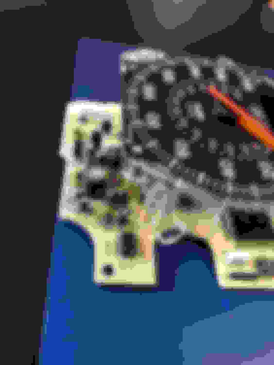
On inspection of the Speedo board, I found the following components that most obviously had burn marks and a couple places with excessive stains that I was curious about:
C4
TR5, TR7
R18
ZD3, ZD4, ZD5, ZD7
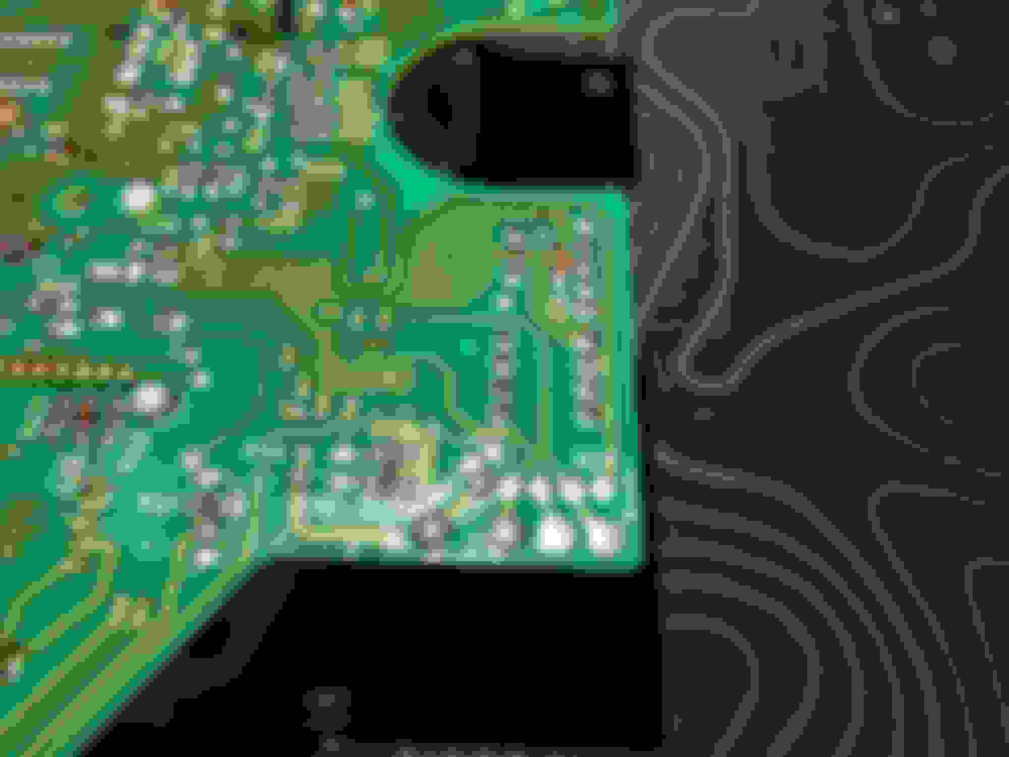
Back of IC3 chip with brown stains (result of resoldering?) See screenshots below:
Stains near two long rows of solder joints near 3Z03 label
From the components thread, looks like I can easily replace everything EXCEPT for the zener diodes, Z3, 5, and 7 which we do not yet have part numbers for. Any suggestions on what I could throw in there to try and replace these?
Also open to any additional scrutiny of the board pictures below.
Clean the flux off IC3. The solder job on IC3 looks poor. Did you have the odometer chip changed? Those burn marks on the diodes are leaked electrolyte from C3. Clean these areas with isopropyl alcohol and a toothbrush or cotton swab. You may have to apply several treatments but it will clean up and neutralize the acid. I've discussed this in the other related thread, "Troubleshooting the FD Speedometer" and may have mentioned it in this thread too. Those Zener diodes should be fine. They are robust units and normally do not need replacement.
You can clean the flux around CON 1 (connector with 3Z03 stenciled next to it) with isopropyl alcohol but you will erase that 3Z03 stamp. That's more of a cosmetic thing.
From the initial look on your board, a capacitor replacement is probably the quickest way to get your board working again. Bear in mind, a capacitor replacement may only fix part of the problem. Other issues may still lurk on the board since we are visually inspecting it.
Thank you for the input. I have never had the odometer changed and when I removed the cluster the first time some years ago, it seemed as thought that was the first time it had been removed.
I made the assumption that bad components would generally have leaked electrolyte around their own pads but honestly, I have no idea what I'm doing.
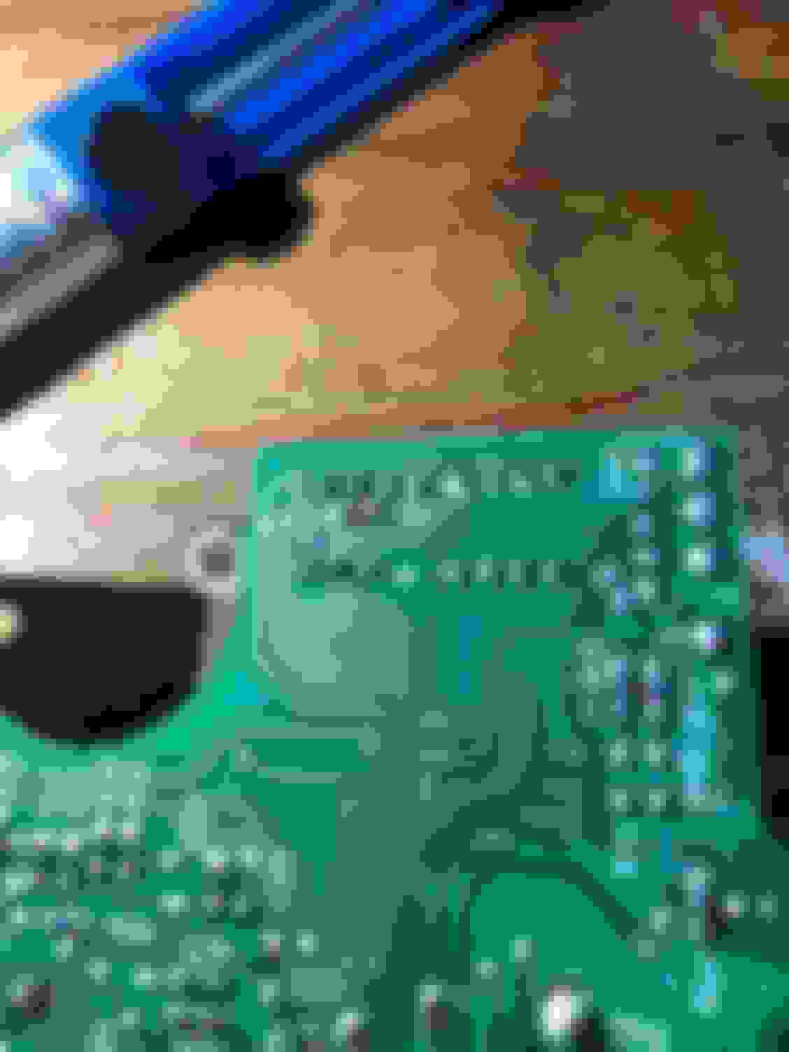
The caps do not seem to be significantly warped (bowed out bottoms or tops) but a few have a bit of electrolyte around their pads. I've included some reference pictures of the caps below but would a safe bet be to replace any caps that appear to have electrolyte at their pads? Or should I only touch the ones that seem to have warped? May need some pointers on what exactly constitutes a bad cap from the pics below
C1, C2, C3, C4, C6
Some electrolyte around the pads @C4 and C2 Side profile of caps
You are welcome and glad to lend a hand. Looking at these photos, C2, C3, C4, and C6 appear swollen. I can't see C1 though. Sometimes, a cap can be bad without any external signs. Most people forget the speedo sits in a vertical position. So when the goo leaks from a capacitor, it runs down its leg(s) then onto the board. Gravity does the rest. You want to pay attention to the legs of surrounding components such as transistors. I've seen the electrolyte eat the legs of a transistor where it meets the body. Some of these transistors are also hard to come by so it's worth taking time to inspect for damage after cleaning with alcohol.
Do you plan to do this repair yourself? Take a look at the photos in this thread and Troubleshooting the FD Speedometer thread. The photos will help you gauge between good, bad, and ugly components. Follow the cleaning recommendations then inspect all component legs for damage, minus the capacitors since they will be replaced anyway. Again, reference the photos to take close-in shots of the legs at various perspectives. You would be surprised what those photos reveal! There is a lot to take in between these 2 threads so don't jump too far down the rabbit hole!
Not to scare you but soldering may look easy but it takes some practice. I don't think you want to practice on your speedo board. Speaking from experience, the board can get easily damaged when not using the proper tools such as too little heat or too much heat from a soldering iron.
If you are unwilling to tackle this soldering project then you could take the board to an electronics shop just for soldering the components. You may want to call and ask around. @rousu had luck with a solder tech, so maybe you two could correspond via PMs to get the right contact info.
As for your IC3, can you post more photos of the top side and backside of the chip? Clean flux from the backside first, please. I want to check for cold solder joints. How long have you had the car and how long has the odometer been blank? Did you say if the odo chip was replaced before? Given the flux residue on that chip, the evidence indicates it was replaced. This chip stores your odometer reading, which is why I'm asking.
So I went ahead and replaced C1, 2, 3, 4, and 6.
I get a tachometer reading now!
However, now my odometer LCD does not light up at all and I still cannot see the numbers :[
I'm going to try and get the rest of the capacitors replaced tonight and try the gauge cluster one more time. Below are the pictures of IC3. I have never replaced the chip myself but it's very possible that somebody take a crack at it before I received the car.
The odometer has been blank since I did the engine rebuild and LED replacement back in late 2017.
Are you replacing those components with the speedo face still soldered into the board? I would encourage its removal to allow greater space to maneuver parts. It's also hard to see the solder joints on IC3. Could you take closer photos of IC3 solder joints? There are a couple of suspect solder joints on it and I want to verify they are ok. What are the black marker strips on the backside of the board, around C26?
When you replaced capacitors C1, C2, C3, C4, and C6, did you observe polarity on the capacitors? The stripe on the capacitor is the negative (-) lead and it should go to the negative terminal on the board. The board should be marked with a "-" next to the negative capacitor terminal.
After you are finished replacing the capacitors, please post photos so I may inspect them for potential cold solder joints. I'm not trying to second guess your work - merely verifying component installation and looking for other potential problems.
Do you have a multimeter available? It may come in handy should you need to verify certain solder runs.
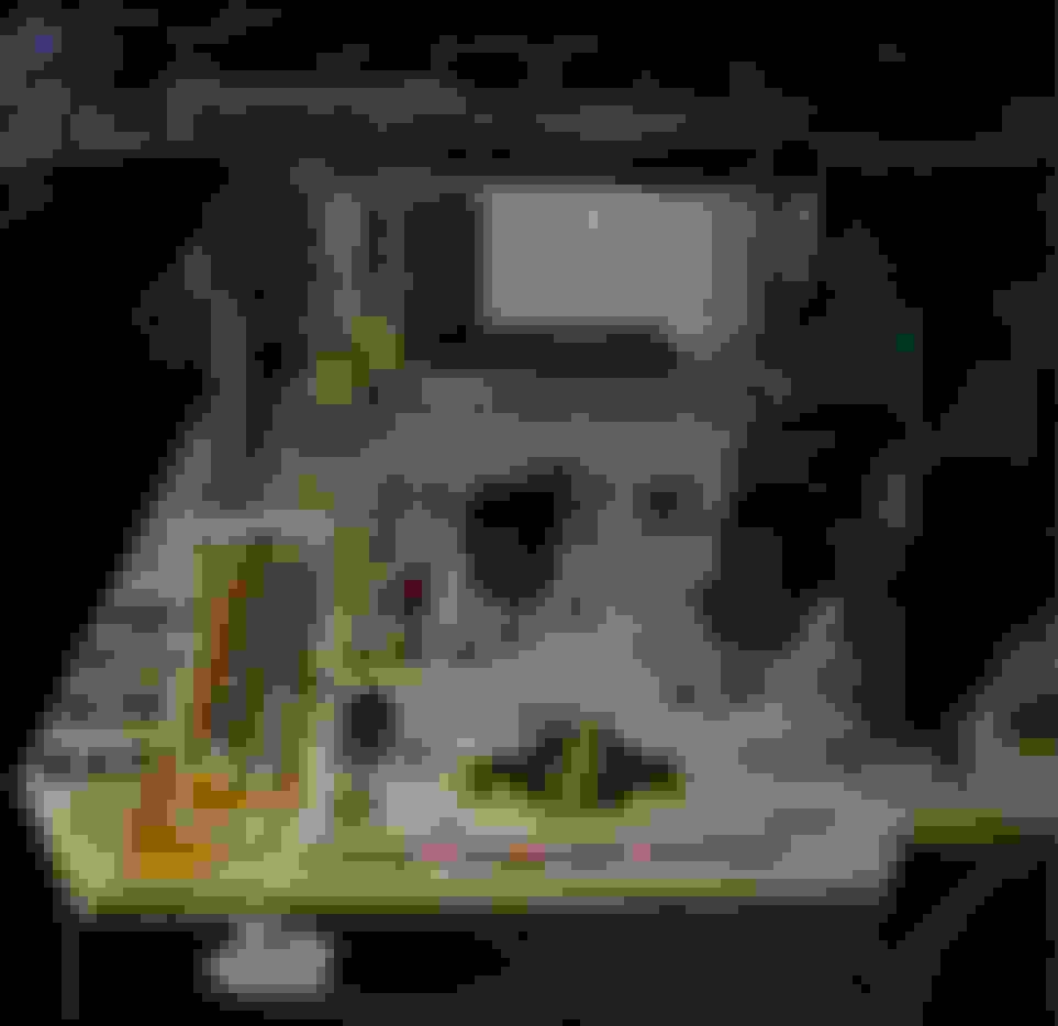
It looks like you cleaned the board nicely. How did the dark spots turn out? Did you also inspect the leads on the affected components, like TR7, DA1, DA2, etc?
Hey @Gen2n3, absolutely reasonable to make sure the fundamentals are taken care of, I did end up taking the speedo itself off to get to some of the inner caps. It's was actually a lot easier than removing the capacitors themselves, my soldering pump has more room to suck more solder off.
-Black marker stripes: Just some marker I was using to mark the terminals I would need to solder off
-IC3 solder joints: Some do look a little suspect, I took some pictures below but resoldered the joints afterwards -Polarity: Went over it again last night and all caps are placed correctly
-Dark spots from electrolyte leakage: Most cleaned up from alcohol and I did not notice any other components in dire need of replacing but my cursory inspection with a flashlight under the board to check the runs and taking a look at the pins could have easily missed something
Caps replaced so far:
C1, 2, 3, 4, 6, 11, 12, 13
Unfortunately, I am in a time crunch to make a track day so didn't have time to wait to source the remaining caps and replace them.
Will test tonight regarding function. With 1,2,3,4 and 6 replaced, I had speedo and tach again but a completely blank odo. This is honestly good enough but I understand that failure of other components may accelerate my replaced components being burned out so decided to replace what I can in caps 11, 12, and 13.
IC3 joints Some of my awful soldering Soldering Mt. Killimanjaro at C12
Quick update after the track day.
Alas, after replacing C1, 2, 3, 4, 6, 11, 12, 13 and resoldering the IC3 chip, the cluster worked for about 30 minutes and is in disrepair again.
I suspect that I may have many more components on the board that are broken despite visually looking ok. My soldering may also definitely be the culprit but the dark marks on the pads of the zener diodes does still lead me to suspect an issue there as well. I'll be checking in on this thread to see when the remaining ZDs are identified!
If you haven't done so already, it should give you some pointers the next time you get behind a soldering iron. It will not make you an expert but these tips should make the next soldering event run smoothly. My #1 tip for soldering - use electrical solder flux!
I did note some of the "mountains" of solder you have on the board. Too much solder is just as bad as not enough or a cold solder joint. The amount of solder you should aim for would be compared to the LCD solder points.
You need to be very careful extracting solder then soldering the speedometer face to the board. The pads on the board already show signs of excess heat damage. That will cause the copper traces to break. The cause for such damage is heat applied over a long time.
I would really like to see more photos of the board after the components were soldered. And also share a pic of the Zener diode solder joints, please. I would highly recommend replacing the solder on the cap above R20 (from the 3rd photo).
I also agree with your remarks, the board should be further examined to reveal other potential problems.
Miraculous update that I'm at a loss for, but during the track day (Nov 2020), the gauge cluster was NOT in a working state after replacing capacitors. The tachometer came on at one point and got stuck at around the 5 o'clock position, way past the RPM max limit and I figured that was that, I would need to get another cluster or go to Powertune for outputs from the PowerFC for a digital dash.
Well, the car sat and wasn't started until Feb 25th and with absolutely NO change to the cluster, everything (except odo) is working. It survived the 2.5 hour trip up to willows, a whole day of romping on thunderhill 5 mile then another 2.5 hours back on a flat spotted tire so plenty of vibrations. It's a small miracle and I don't know how long it will last but I haven't had a working cluster since the rebuild in 2017 so it felt great.
Thanks gentlemen for all the assistance!
If it goes out again, I think I'll probably be in the middle of a Haltech or Adaptronic conversion so can hopefully use some CAN gauges instead
Thanks for all the info on this thread. I have just fixed my odometer following the advice on here. Replaced all the capacitors even though only two had leaking electrolyte... Still didn't work! Under closer inspection of the board ZD4, 5 and 7 were showing corroded contacts from a bad C3, replaced them with new 4.7v and 2x 5.1v zener diodes. Works just like it should now.
Many thanks
Hi, I leave in Rome, in Italy. I have a Mazda Rx7 Fd 1993 with problem at the odometer. The lcd is working on with red led, but i can see the number of km. I have take off the speedometer e leave to a laboratory to change the capacitors but i'm not sure that the job was make good (sorry for my english)
I'm searching someone that i can send my odometer e can try to repair. I think the logic board must be cleaner with alcool and then check the capacitor, transistor and soldering.
Post photos of the speedometer board here. Use the camera's zoom function to take photos of the capacitors. I could help find problems on the speedometer but you may need to find a local electronics repair shop who could replace any bad components. It may take a few times to fix the odometer so please be patient.
Post photos of the speedometer board here. Use the camera's zoom function to take photos of the capacitors. I could help find problems on the speedometer but you may need to find a local electronics repair shop who could replace any bad components. It may take a few times to fix the odometer so please be patient.
Hi Gen2n3; yesterday i have sent the logic board to a electronics repair. He check for me the capacitor and the other components a can try to repair. When the logic return i will check if working. if not, i re wrote here for help ;-) i hope to repair! tanks
 09-24-20, 04:01 AM