
JDM wiring harness on a spec
 05-22-12, 11:59 PM
#26
Tundra driver, Rx-7 pilot
iTrader: (1)
Join Date: Nov 2004
Location: Everett, Washington
Posts: 150
Likes: 0
Received 0 Likes
on
0 Posts
So according to everything above, I have everything wired up correctly... I think. I tested power to my injectors, and I now have 12 volts going to them. I also have fuel pressure to the rail. My injectors will still not fire. I even pulled spark plugs with the egi fuse still in and cranked. No fuel spraying. Does anybody have any idea why this could be happening?
 05-24-12, 09:17 AM
#27
Aviation Machinist Mate
did you find the x-14 connector? if not its its between the blower and the firewall. also did you follow the step that i did? did you check your voltage from the x-05 front all the way to the injector clips? lmk
05-24-12, 10:02 AM
#28
Tundra driver, Rx-7 pilot
iTrader: (1)
Join Date: Nov 2004
Location: Everett, Washington
Posts: 150
Likes: 0
Received 0 Likes
on
0 Posts
I found the x-14 connector and connected it. I will test for continuity from the x-05 front to the injector clips next. When you say to test that, you are talking about the brown/orange wire all the way to the injector wires themselves, correct? Thank you for responding. I really appreciate it.
05-26-12, 04:10 PM
#29
Tundra driver, Rx-7 pilot
iTrader: (1)
Join Date: Nov 2004
Location: Everett, Washington
Posts: 150
Likes: 0
Received 0 Likes
on
0 Posts
Ok, I tested power from x05 front to the injector clips and everything checks out ok. Can anyone think of a reason why my injectors are not pulsing? Is there an injector silonoid that could be malfunctioning?
05-27-12, 03:36 AM
#30
Aviation Machinist Mate
i had the same problem while doing this mod. all i can remember was i had the injectors B/Y(EM) connected to pin G/B (FRNT). I was getting good 12v, fuel press, but the engine just cranks all day. so i went back and re-verified each pin again and i accindently swapped pin B/L with G/B on the x-05 connector. so just makes sure the B/L and B/O mates together. try it again and lmk.
X-05 FRONT 10 PIN CONNECTOR
| G |BL/G|XXXX XXXX| V/W | Y |
|G/W|W/G| B/W | G\B | B/O | BR/W |
X-05 USDM (EM)10 PIN CONNECTOR
|B/L|BR/B| XXXXX | Y | B/G |
|BR | R |B/W|W/L | B/Y |BR\W|
X-05 FRONT 10 PIN CONNECTOR
| G |BL/G|XXXX XXXX| V/W | Y |
|G/W|W/G| B/W | G\B | B/O | BR/W |
X-05 USDM (EM)10 PIN CONNECTOR
|B/L|BR/B| XXXXX | Y | B/G |
|BR | R |B/W|W/L | B/Y |BR\W|
05-29-12, 04:42 PM
#31
Tundra driver, Rx-7 pilot
iTrader: (1)
Join Date: Nov 2004
Location: Everett, Washington
Posts: 150
Likes: 0
Received 0 Likes
on
0 Posts
I know it sounds stupid to ask, but could you actually spell out the full title of the colors that are important to match up? Also can you explain which orientation is which? Like are those views looking at or behind the connector? Sorry, I just need to get this right, and thank you.
05-30-12, 04:32 AM
#32
Aviation Machinist Mate
I know it sounds stupid to ask, but could you actually spell out the full title of the colors that are important to match up? Also can you explain which orientation is which? Like are those views looking at or behind the connector? Sorry, I just need to get this right, and thank you.
for example your reading x-05 ( EM) BLK/BLU from your top left and you connect it to x-05 ( Front) Green your top right
X-05 FRONT 10 PIN CONNECTOR
| GREEN | BLKBLU/GRN |XXXXXXXXXXX| VIO/WHT | YELLOW |
| GRN/WHT |WHT/GRN|BLK/WHT|GRN/BLK| BLK/ORG | BRN/WHT |
X-05 USDM (EM)10 PIN CONNECTOR
| BLK/BLU | BRWN/BLK | XXXXXX XX| YELLOW | BLK/GRN |
| BRWN| RED| BLK/WHT | WHT/BLU| BLK/YEL | BRWN/WHT |
i hope this explains it. lmk
06-14-12, 07:23 PM
#33
Junior Member

Join Date: Feb 2012
Location: Pa
Posts: 7
Likes: 0
Received 0 Likes
on
0 Posts
ORIGINAL PIN DIAGRAM OF USDM X-05 (F) TO X-05 (EM) CONNECTOR
X-05 FRONT 10 PIN CONNECTOR
| G |BL/G|XXXX XXXX| V/W | Y |
|G/W|W/G| B/W | G\B | B/O | BR/W |
X-05 USDM (EM)10 PIN CONNECTOR
|B/L|BR/B| XXXXX | Y | B/G |
|BR | R |B/W|W/L | B/Y |BR\W|
X-05 JDM (EM)12 PIN CONNECTOR
| B/L |BR/B | Y | XXXXXXXXXXX| B/G | W/L |
|BR | R | B/W | BR\Y | B/Y | XXX |BR/W|
NOTE: PLEASE REMOVED ALL PINS BEFORE STARTING THIS MODIFICATION. NEXT, YOU NEED TO MODIFY THE JDM X-05 12 PIN (BLUE) CONNECTOR AND MAKE IT TO A 10 PIN CONNECTOR. I USED A DREMEL TO CUT MY OFF. CUT THE B/L AND BR PIN CONNECTOR OFF.
X-05 USDM (EM)10PINS
B/G - EGR
Y- 1ST GEAR
BR/B - TPS
BR/W - PRESS SENSOR
B/Y - INJECTOR 12V
W/L - COOLING RELAY
B/W - SOLENOID VALVES
R - 2ND GEAR SWITCH
BR - TRANNY
B/L - EGR
X-05 JDM (EM)11 PINS
B/L-EGR
BR/B - TPS
Y - 1ST GEAR
BR - TRANNY
R - 2ND GEAR SWITCH
BR/Y - FUEL TEMP SENSOR
BR/W - PRESS SENSOR
B/Y - INJECTORS 12V
B/W - SOLENOID VALVES
B/G- EGR
W/L - COOLING RELAY
NOTE: BR/Y WIRE(FUEL TEMP SENSOR) GOES TO X-14 AND PIN IT TO THE BLUE WIRE ON X-14 (white connector under the DASH).
02-06-17, 08:20 PM
#34

can anyone answer this? I'm wondering the same thing. There are two blue wires already on the x-14 plug. Thanks
02-06-17, 09:04 PM
#36
really? I'm actually showing a check engine light because of this. Thanks for your reply. Right now I'm trying to find the JDM x14 connector and trying to see what the blue wire that I'm supposed to pin to and see where that goes on the JDM harness. If that makes sense.
02-17-17, 06:45 PM
#39
Senior Member
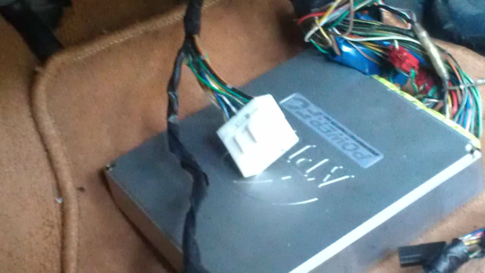
the mysterious white connector
I apologize for resurrecting a dead thread. So im lame terms, should I be cutting off the JDM x-05 connector from the main engine harness and splicing in the USDM x-05 connector, splicing COLOR to COLOR, EXCEPT for the one brown/yellow wire? Or is there a certain wire from the JDM harness that needs to go to the USDM x-14 white connector with a blue wire?
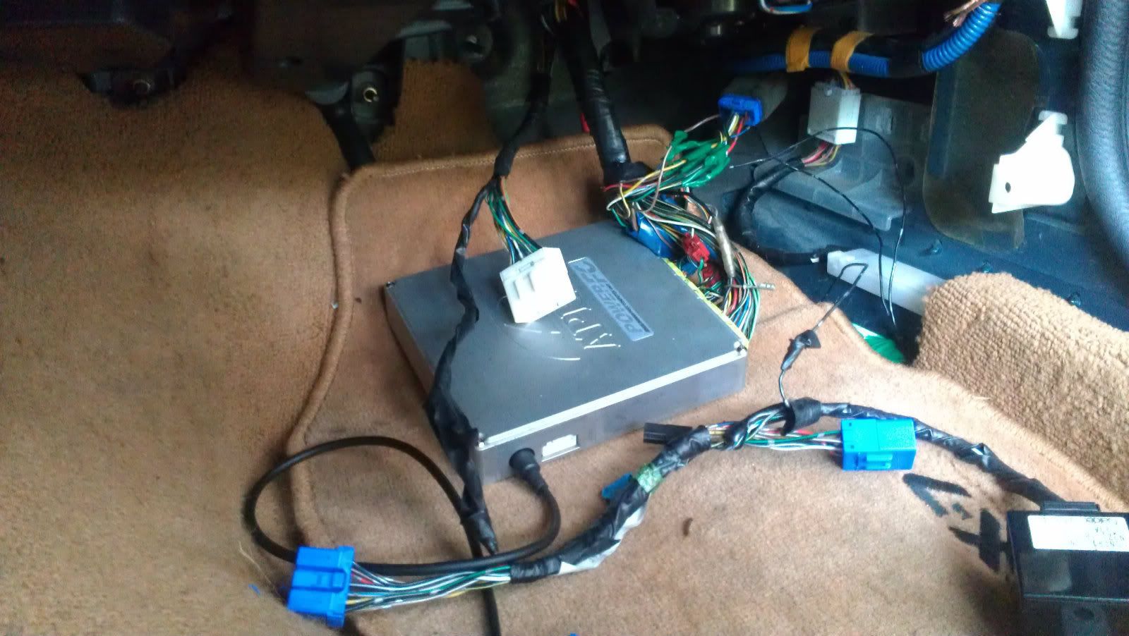
Also, what exactly is this white connector here, and where does it need to be connected?
I also notice that the x-05 connector does not need this extension piece to fit into that other part. Is it necessary to be hooked up? it looks like in the picture above they have it hooked up directly. I apologize again for being so electrical illiterate. Someone to coach me through this part would be greatly appreciated. I am thinking this is the reason I have no power to my injectors.
02-20-17, 11:13 PM
#40
Senior Member
Someone posted that it goes to a connector up on the firewall, but what function does it support in the electrical system? Little white orphan. Lots of wires coming out of it.
Last edited by rousu; 02-20-17 at 11:20 PM.

Thread
Thread Starter
Forum
Replies
Last Post
82streetracer
1st Generation Specific (1979-1985)
7
08-23-15 09:28 AM