
I'm stumped. Fuel pump power

I'm stumped. Fuel pump power
I had my car in storage for the winter and drove it home a month or so ago, I took out the engine and transmission for a trans rebuild. I got it put back together the other day, but when I turn the key I don't hear the pump.
I got the pump out and tested it on the workbench with a spare battery and it works just fine, tested both through the connector wiring and straight to the pump wires. Next I jumped the diagnostic box F/P to GND and with the key on I get 12.8 volts at the connector outside of the tank, I connect that to the hanger wires and also get 12.8 volts at the connector inside the tank. So I'm getting 12v everywhere inside the car, and the pump turns on when connected to an external 12v, but when I connect the pump to the cars wiring, I get nothing. I know it has to be something dumb I'm missing here...
edit: this is a walbro 450 e85 pump re-wired to the bin with an inline fuse and relay
Last edited by needspartsnow; May 3, 2019 at 02:23 PM.
The only conclusion I can come to is the multimeter may be showing 12v but there isn't enough amperage to turn the pump.
Could I be seeing 12v at the connector but have a bad ground somewhere causing a loss of amperage? I'm hopeless when it comes to electrical. Could a bad ground at the engine harness cause this? I did unhook the engine harness to remove the engine and reconnected the harness grounds, one to each rotor housing and the ground from the charge harness bolted to the front iron. This is driving me crazy
Could I be seeing 12v at the connector but have a bad ground somewhere causing a loss of amperage? I'm hopeless when it comes to electrical. Could a bad ground at the engine harness cause this? I did unhook the engine harness to remove the engine and reconnected the harness grounds, one to each rotor housing and the ground from the charge harness bolted to the front iron. This is driving me crazy
Can you measure the voltage at the connector with the pump connected normally? That way you can see any voltage drop under load if that is what you suspect.
There is another ground strap from the firewall to the uim but i doubt it's related.
There is another ground strap from the firewall to the uim but i doubt it's related.
I know the uim ground strap you are talking about, that has been disconnected since converting to single turbo about 9 months ago, everything worked fine without it.
Yeh you have significant voltage drop under load, which is why it's not working. Do you have a picture of how it's wired relay wise? And does the relay have a direct connection to the battery or is it pulling power from factory wiring?
Joined: Nov 2011
Posts: 3,425
Likes: 489
From: okinawa to tampa
If you still have the fuel pump resistor under your brake booster, unplug it, jump the wires together and delete the box. Even with the fuel pump rewire, the circuit still runs through that resistor.
Trending Topics


Seeing 12V with the pump disconnected but 4V with the pump connected means there is probably too much resistance in the wiring (and/or connectors) between the battery and the fuel pump. If you use the multimeter to measure the resistance of the fuel pump, it's probably somewhere around 0.5 - 2.0 ohms, which means the fuel pump would draw about 6 amps - 24 amps... I'm just guessing at these numbers, the spec sheet for your fuel pump should help with exact values. In an ideal setup, the resistance of the wires (and connectors) should be much lower than the resistance of the device or the wires will prevent the device from receiving full power. For instance, adding 0.5 ohms of wire resistance to a 0.5 ohms fuel pump would limit the current down from about 24A to about 12A, which is going to prevent the fuel pump from flowing as much as it should.
One possible way to troubleshoot is using the multimeter to check voltage between the battery and each connection in the circuit, from the fuel pump relay to the fuel pump connector. For instance, the circuit probably goes Battery >> wire1 >> Fuse >> wire2 >> Relay >> wire3 >> Fuel Pump Connector. With good wires you should see less than 1.0V difference between the battery (which might be 12.8V) and the fuel pump connector (which should be 11.8V or higher when the pump is plugged in and wiring is good).
Use the multimeter to measure the voltage between the battery and ground, that's easy it should be 12.8V. Next measure between the fuse and ground, should be 12.7V or greater. Next measure between the Relay and ground, should be 12.6V or greater, if it's less than 11.0V there is likely too much resistance in wire2... if there had been too much resistance in wire1 you would have noticed low voltage when measuring the fuse. Hopefully that helps, you can post your measured voltages at each point if you need additional help troubleshooting. Electrical only seems like black magic, the rules and math aren't too bad once you've spent some time learning and working with it.
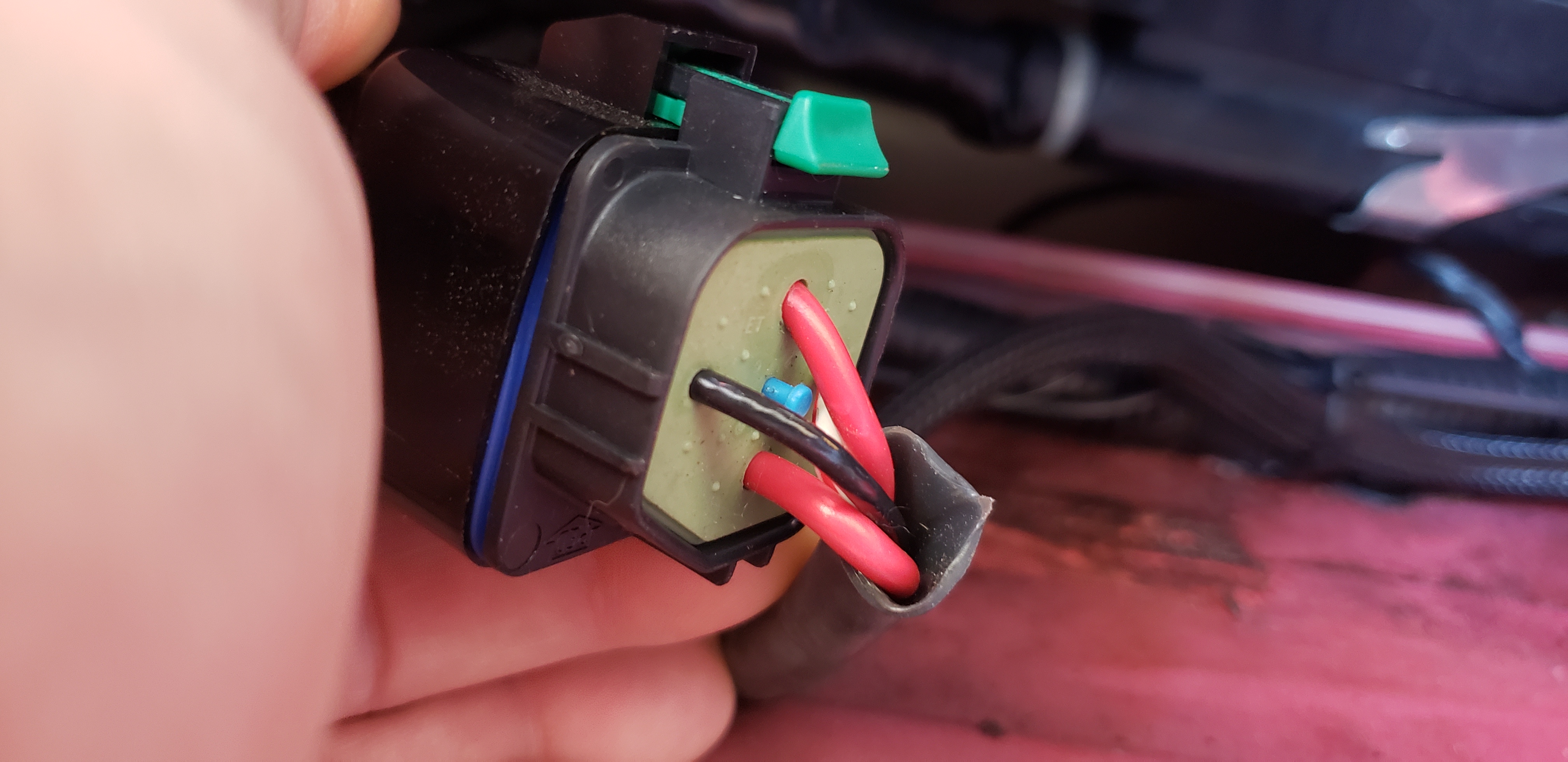
relay:
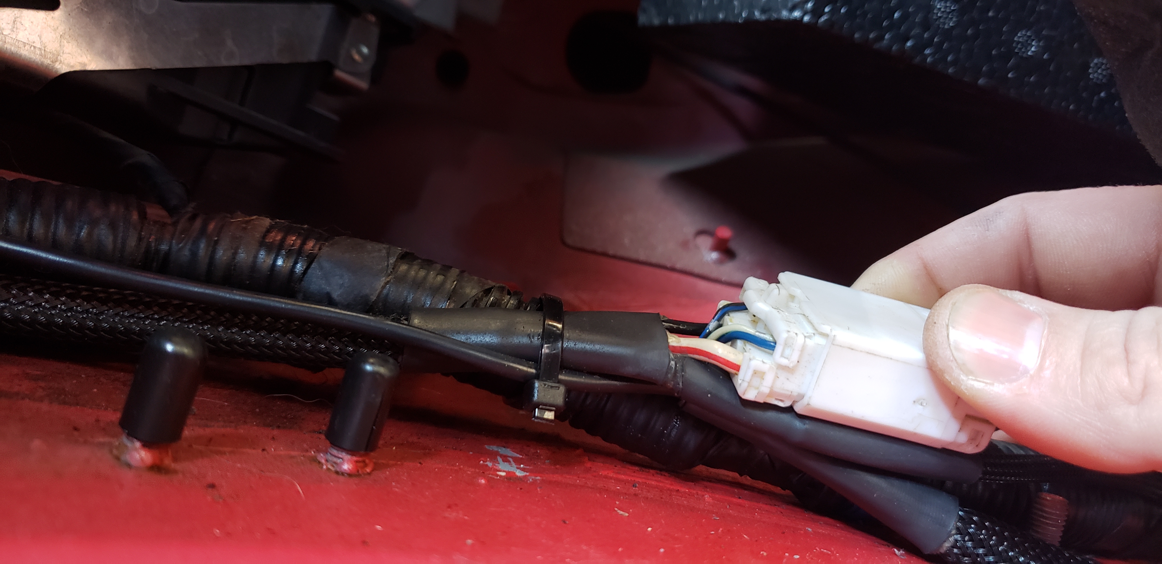
white plug feeding the relay:
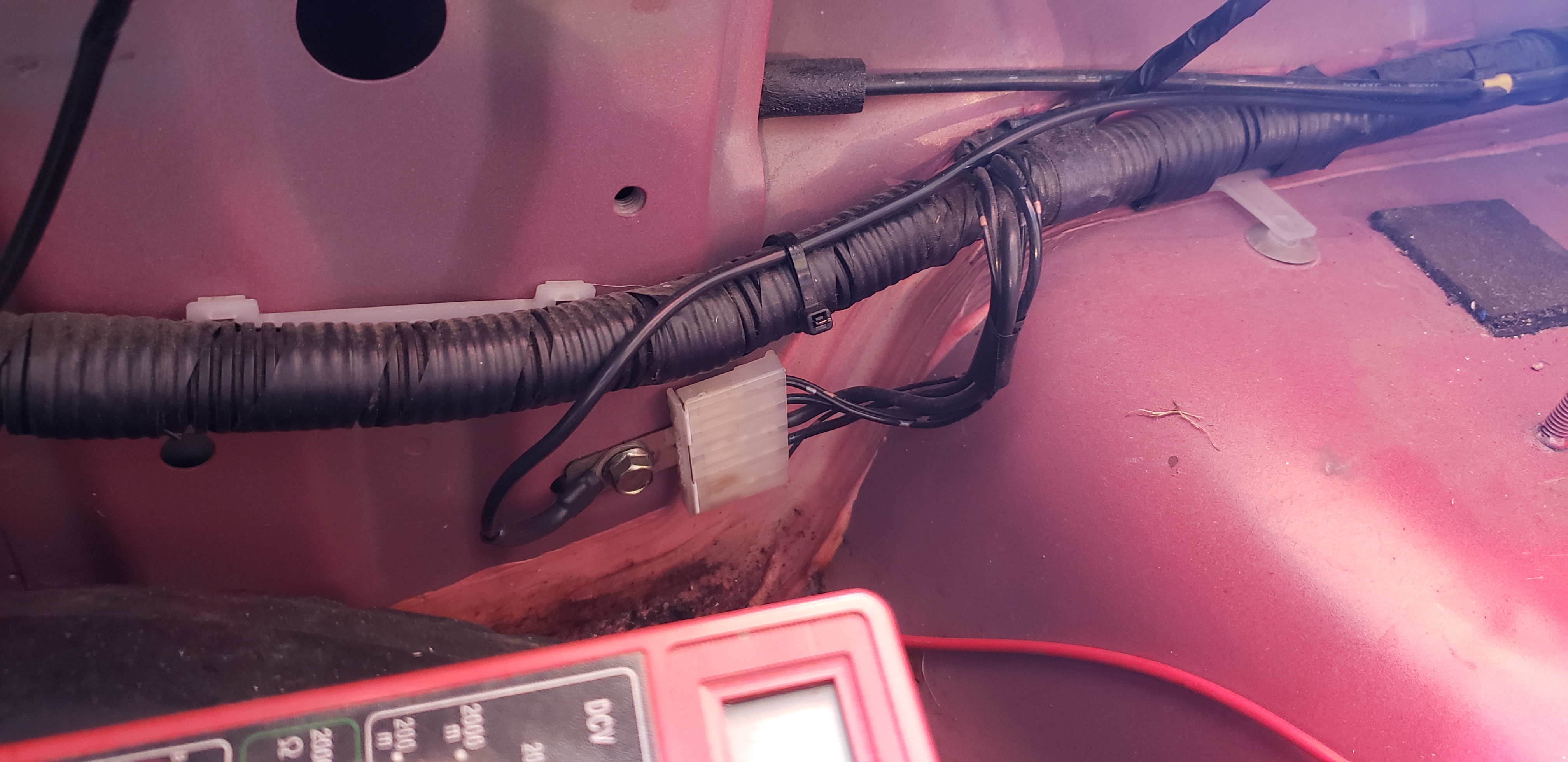
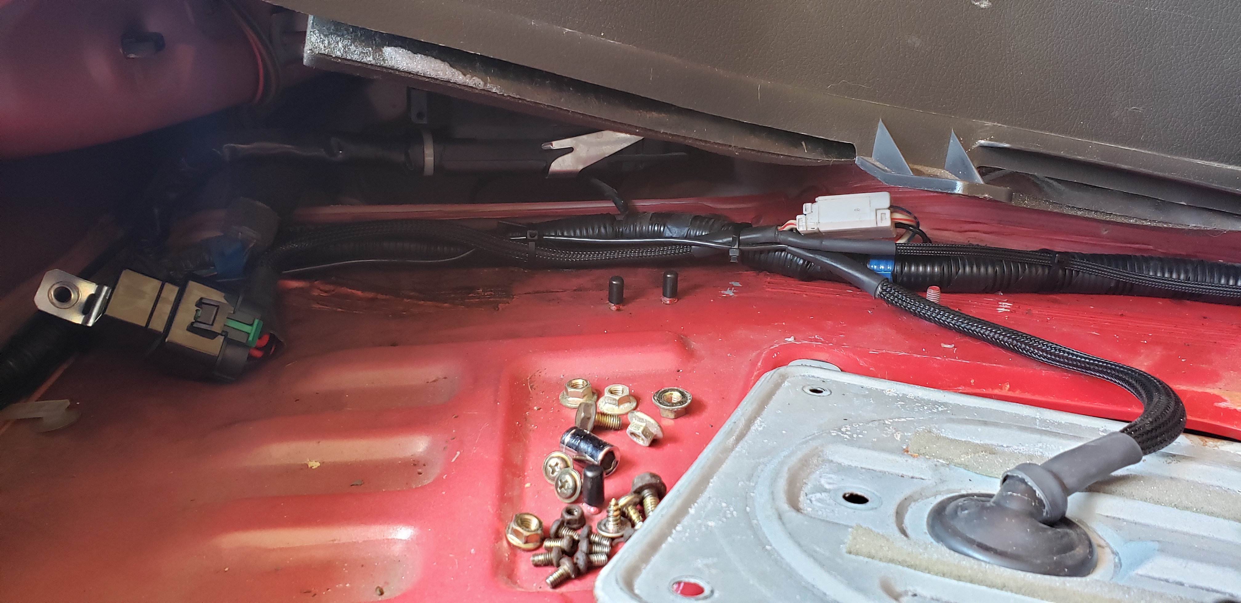
ground location in the trunk:
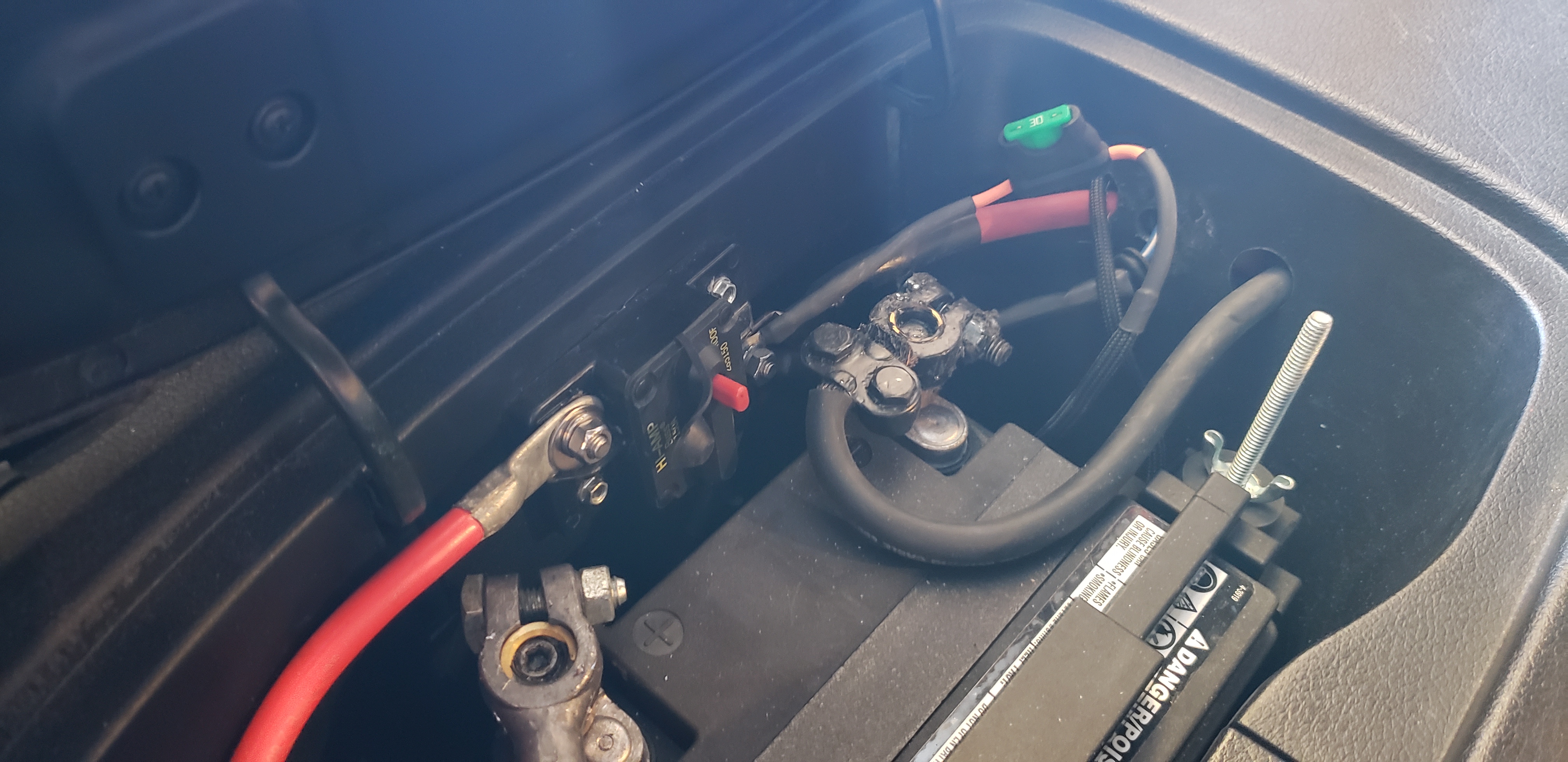
battery set up, inline fuse going to relay:
zoomed out pic of everything:
Scotty305
I measured voltages from the locations you posted, all voltages were exactly as you said they should be.
edit: I should say I got 12.6v from the relay where the bottom (as posiitioned in my pic above) red wire is connected. 0 volts at the pin where the top red wire (the one closest to the release tab) connects to the relay.
Last edited by needspartsnow; May 4, 2019 at 12:46 PM.
This seems like it's becoming very common now, I just posted this in another thread a few days ago. I had a similar issue and the problem was the plug from the pump to the underside of the hanger was a poor connection. It had nearly melted itself. I bought a bulkhead connector to bypass it and bring the power directly to the pump.
That solved the problem for me.
Vince
That solved the problem for me.
Vince
Those measurements will only be useful with the relay active, so the fuel pump should be running. The way resistance works, the voltages tend to look OK when there's nothing trying to draw power from the circuit.
I was hoping to avoid boring you with too much math, but it's just first-year algebra and first-semester circuits and I've got a few minutes to spend typing so here goes. The main electrical formula that's useful is Volts = Current * Resistance, and you can also shuffle that around to be Current = Volts / Resistance or Resistance = Volts/Current. (formula is named Ohm's law, don't worry about that too much). Why do we care? Because when wires work perfectly we over-simplify and assume the wire resistance is 0.000 ohms. When wires are too small, or connections are poor, the extra resistance prevents the device from getting enough power (voltage & current) to work properly.
Let's punch in some numbers. Walbro site claims 465 L/hour fuel flow at 13.5V (14.1 amps). We can use one of those formulas above to calculate pump resistance... Pump Resistance = (13.5 Volts / 14.1 amps) = 0.95 ohms. So if you connect straight to your battery at 12.8V, we can assume the resistance will stay the same and the current will change... Current = (12.8 Volts / 0.95 ohms) = 13.47 amps. The pump will flow a little less with lower voltage/current, that's why too much wire resistance is a problem.
For instance, in a normal working circuit the resistance for a length of 10AWG wire should be very low, let's say 0.01 ohms max. Relay and fuse resistance should also be low, let's say 0.02 ohms total. In that example, total resistance for the circuit is now 0.95 ohms (pump) + 0.01 ohms (wire) + 0.02 ohms (relay/fuse) = 0.98 ohms. So total current draw for the circuit will be (12.8 Volts) / (0.98 ohms) = 13.0 amps. So the pump is receiving a little less current than it would in a perfect circuit with wires so thick they had 0.000 ohms resistance. You can also calculate the voltage at the pump in this real-life example, using one of the formulas above... multiply the pump resistance by the total current... Pump Voltage = (Pump Resistance) * (total current) = (0.95 ohms) * (13.0 amps) = 12.35 volts even with very low resistances for the wires and fuse/relay. This is why wire gauge/thickness is important, because thicker wire tends to have lower resistance and lets more voltage go to the fuel pump instead of being wasted as voltage drop across the wires. This is also a reason you might want to use a beefier relay; even though the pump doesn't actually draw 50A that relay should have beefier parts inside so it will have lower resistance (less voltage drop) than a relay that can only handle 30A max.
Let's do another example, assuming your wires are 0.05 ohms, and a bad relay has too much resistance and is 0.50 ohms... the total resistance for the circuit is now 0.95 (pump) + 0.05 (wire) + 0.50 (bad relay) = 1.50 ohms. So total current draw will be 12.8 Volts / (1.50 ohms) = 8.5 amps, that's about half of what it should be. If you measure voltage at the pump it will be Pump Voltage = (Pump Resistance) * (total current) = (0.95 ohms) * (8.5 amps) = 8.1 volts which means your fuel pump is flowing only about half as much as it should, if that's even enough voltage for it to run at all.
Congrats if you made it this far, don't feel too bad if you skimmed through.
Here is why your measurement only matters when the relay is active and trying to send power to the fuel pump... an open circuit will have very high resistance, like over one million ohms. When I say an open circuit I mean a relay not active, or a wire only connected to air. So let's re-do those same calcs again... with the same too-high wire and fuse/relay resistance. Total resistance of the circuit (with air gap between the pump and the relay because relay isn't active) will be 0.95 (pump) + 0.05 (wire) + 0.50 (bad relay) + 1000000 (air gap) = 1000001.5 ohms. Total current draw will be 12.8 Volts / (1000001.5 ohms) = 0.000013 amps. It would actually be lower because an air gap is over 1 million ohms, but this is already complex enough. So the voltage at the fuel pump when the relay is off would be Pump Voltage = (Pump Resistance) * (total current) = (0.95 ohms) * (0.000013 amps) = 0.00001 volts. All the voltage drop is across the air gap, so you'll measure 12.79999 volts if you check the voltage at the relay.
Long story short, do those voltage measurements when the relay is active and trying to send power to the fuel pump. When the relay is trying to send power to the pump is when the voltage measurements will help you find an electrical problem.
Joined: Nov 2011
Posts: 3,425
Likes: 489
From: okinawa to tampa
In your picture of the battery and inline fuse, the circuit breaker looks like it is tripped. The red reset button appears to be out. I'm sure that's not the issue, but I've made worse mistakes.
I worked on a Dodge with a cummins for about 3 hours trying to get it to start before i verified that there was actually fuel in the tank... The gauge showed 3/8 of a tank.
2nd option: with the jumper at the diagnostic connector in place, remove your relay and jump the 2 red terminals together to bypass ir. This would verify whether or not the relay was bad. I've seen the contacts get so pitted that they can't carry a load.
Vince
Where is your fuel pump grounded? If power is just battery -> relay -> pump then there shouldn't be much that can go wrong on that side as long as the relay is good.
If I remember correctly, isn't there a ground strap at the pump bracket? If that ground sucks then you're not going to get good power to the pump.
If I remember correctly, isn't there a ground strap at the pump bracket? If that ground sucks then you're not going to get good power to the pump.
In your picture of the battery and inline fuse, the circuit breaker looks like it is tripped. The red reset button appears to be out. I'm sure that's not the issue, but I've made worse mistakes.
I worked on a Dodge with a cummins for about 3 hours trying to get it to start before i verified that there was actually fuel in the tank... The gauge showed 3/8 of a tank.
2nd option: with the jumper at the diagnostic connector in place, remove your relay and jump the 2 red terminals together to bypass ir. This would verify whether or not the relay was bad. I've seen the contacts get so pitted that they can't carry a load.
Vince
I worked on a Dodge with a cummins for about 3 hours trying to get it to start before i verified that there was actually fuel in the tank... The gauge showed 3/8 of a tank.
2nd option: with the jumper at the diagnostic connector in place, remove your relay and jump the 2 red terminals together to bypass ir. This would verify whether or not the relay was bad. I've seen the contacts get so pitted that they can't carry a load.
Vince
I took the relay to the bench for testing, with terminals 85 and 86 hooked up to a spare battery the relay clicks like it should. While it was hooked to the battery I put the multimeter on terminals 87 and 30 to measure ohms. I'm getting a reading that is bouncing around between .15 and .3 Is this my problem? from my understanding the ohm reading should be .01 or .001? I'm completely new to relays and how they work so hopefully this information is relevant and puts me back on the right track.
Where is your fuel pump grounded? If power is just battery -> relay -> pump then there shouldn't be much that can go wrong on that side as long as the relay is good.
If I remember correctly, isn't there a ground strap at the pump bracket? If that ground sucks then you're not going to get good power to the pump.
If I remember correctly, isn't there a ground strap at the pump bracket? If that ground sucks then you're not going to get good power to the pump.
Got it figured out. Bad relay.
I learned some valuable lessons here, what a mindfuck.
1. The problem might not be in the area you were last working. It could be a completely seperate and random event.
2. Just because the multimeter says you have 12v, doesn't mean you do.
3. When you test a relay, just hearing it click doesn't necessarily mean it is good.
4. Just because a part is only months old, it doesn't mean you shouldn't take a hard look at it.
Thanks guys for keeping me going on this. I was ready to quit and call a professional.
I've seen a number of cheap aftermarket relays crap out. It can be tough to find one that's OEM quality. Pretty much any relay from the parts store is going to be crap.
Glad to hear you sorted it out~!
Dale
Glad to hear you sorted it out~!
Dale
Joined: Nov 2011
Posts: 3,425
Likes: 489
From: okinawa to tampa
Jeeeez.... origami mindfuck. Sir, if my multimeter says 12v I take it as gospel. I could not imagine a world where my favorite tool would lie to me. The betrayal would just kill me
^It wasn't lying, because he saw the voltage go away under load when the pump was connected.
The biggest take away here when testing electrical issues is to see if it can support the load required. In most electrical sections of Factory Service Manuals, they will say "using a sealed beam headlight, confirm circuit operation under LOAD".
Now this only applies to circuits with a 10 amp fuse or greater, because that bulb would probably blow the fuse. This is a good practical test to verify a circuit's integrity.
At my day job as a Fire Alarm Technician, i'm constantly dealing with similar situations. Most of the accounts are in Ocean City and corrosion takes its toll on everything. Poor installations where wires are nicked eventually leads to the wire degrading until it's thinner than a hair and is finally unable to carry enough current to operate. At least in those situations, you know you are in the right place because you'll find a bunch of blue corrosion where the copper has been eaten away.
Cars are definately not as easy because you have so many "black boxes" that apparently operate on witchcraft and little documentation to be able to test them.
But at least he got it figured out! The forums are still relevant and helpful.
Vince
Sometimes just an old fashioned test light works better just because it simulates a load, albeit not very high current. Easier if you don't fully understand how to use a multimeter, voltage drop, etc
Glad you're making progress. Not everyone knows this, but it's pretty common for most motors (like fuel pumps, radiator fans) to draw more current when they are first getting started from a stop. For instance, even though the Walbro site says your pump will draw about 14 amps during normal operation I wouldn't be surprised if it draws something between 20-30 amps when the pump first turns on. Most automotive fuses allow a bit more than the rated current before they trip... so a 20A fuse might not pop if the current goes to 25A just for a second or two. If your relay is rated for 20A, it may wear out sooner than expected because of how much current the pump draws when it starts. This is another reason it's wise to use a relay that has a good margin of safety.
Joined: Nov 2011
Posts: 3,425
Likes: 489
From: okinawa to tampa
Fuses and circuit breakers are rated for 50% more amps than what that circuit normally draws............ on airplanes anyway. I would imagine it be the same for cars

Thread
Thread Starter
Forum
Replies
Last Post
FCakezilla
SE RX-7 Forum
5
Jul 19, 2018 12:44 PM
DREYKO
2nd Generation Specific (1986-1992)
9
Jan 7, 2007 10:14 PM
Hondagoldwingrider
2nd Generation Specific (1986-1992)
5
Sep 12, 2006 05:50 AM