When you click on links to various merchants on this site and make a purchase, this can result in this site earning a commission. Affiliate programs and affiliations include, but are not limited to, the eBay Partner Network.
I have to start by saying that I'm a big fan of the stock sequential system, probably because I spent time fixing it. I'm just bored tonight since it's snowing and I have nothing to do but it got me thinking of the secondary turbo and it's piping, which is rather twisty.
What about keeping flow more linear and making a custom inlet pipe?
I have said this before. cold air is what you want to feed those turbo's with. The location of the tip of the ***** in your photo is by the exhaust and I wouldn't want to suck that air there.
You know I thought about this a few times...just looking at how much longer the secondary intake path is compared to the primary. But I guess its just too close to the downpipe...maybe if you had it picking up air that is passing below the car, and somehow really shielding off the heat coming from the DP maybe it would work fine. And it would de-clutter the engine bay a bit...which is always nice.
^that shouldnt matter. the turbo will pull the air it needs. the heat is the only problem, well and perhaps water on the road but i doubt that would matter if you avoid puddles lol
I'm planning on making a better intake piping system.
Your parts are legendary, I would be the first to buy a hi flow secondary turbo pipe. I think you should make a run at the M2 medium replica and an intake box, then turbojeff would be like the new PFS.
Efini Y pipe. And IIRC...later model (96+) primary intake elbow was improved.
This....then work on heat management. I have a ceramic coated AND wrapped downpipe. My secondary inlet pipe is also wrapped with heat reflective tape. Both intakes are routed to only be able to draw air from the area next to the radiator(similar to M2 intake)
I do have a wrapped downpipe. It bothers me however that the pipe bottlenecks at the turbo inlet in a bad angle. Maybe a similar pipe but with smoother transitions. I'm sure gains might be negligible but a gain is a gain nonetheless. I'll be working on a heat shield though for that pipe to insulate better from the exhaust.
Your parts are legendary, I would be the first to buy a hi flow secondary turbo pipe. I think you should make a run at the M2 medium replica and an intake box, then turbojeff would be like the new PFS.
Efini Y pipe. And IIRC...later model (96+) primary intake elbow was improved.
Yes and they changed the design for the rear turbo inlet pipe (rubber hose) and IC piping as well. I haven't seen the front turbo inlet piping but I have seen the updated primary elbow. OEM design for the 93-95 (in US) intake tract piping looks restrictive all around. If you replaced your IC then you only have to work on the turbo inlet piping. The JDM cars will have a steering shaft in the way probably greatly reducing the options for redesign on that pipe for JDM cars. USDM cars don't have the steering shaft constraint.
Maybe instead of a efini y pipe a costume one sorta like the one in the pic looks like its more for non sequential setup but I bet u could get it set up to run sequential
I have thought of the under the car 2ndary turbo intake as well as the convoluted intake tube looks fairly restrictive.
I think the bigger restriction is the primary and 2ndary turbo exhaust side dead heading and exhausting 90 deg with another tight 90 deg in the downpipe.
Go ahead and rotate the entire 2ndary turbo so you have a straight intake path with a nice source for a cold air intake and the ability to run a downpipe off each turbo.
Balljoint gained 50hp off just using an external WG on twins (475rhwp over 425rwhp), so the exhaust restriction definitely needs reducing.
Ok so the ***** intake is pretty funny but it raises a good point.
We talk about delivering cold air to the engine a lot, but there's an element to intake design that is often overlooked or misunderstood. That element is restriction's effect on the compressor efficiency and compressor wheel speed.
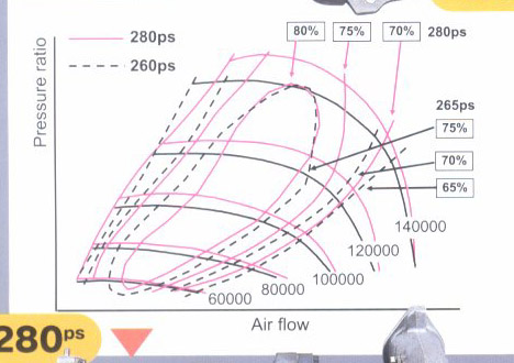
Here are compressor maps of the 93 and 99 turbos that somebody posted a while back:
Notice on the Y axis that is says pressure ratio. Most people just use manifold pressure as an approximation for this, but pressure ratio actually takes into account the restriction in the inlet and the airflow. It is compressor outlet pressure divided by inlet pressure, called (p2/p1) on compressor maps. So when you plot an engine on a compressor map, it's usually higher on the map than you think it is. It matters a lot more if you are pushing a turbo near the edges of its efficiency, as is often done on stock turbos.
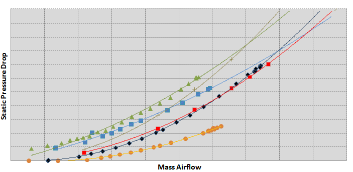
Here's a chart that illustrates what's going on:
Each of those are different stock intake systems on turbo cars. X axis is mass airflow, measured in a lab, and y axis is the pressure drop at the compressor inlet, measured by a high resolution pressure transducer. Notice:
1) pressure drop increases exponentially with airflow
2) more restrictive systems have a much steeper pressure drop curve
The result can be a much higher compressor wheel speed, moving to a more inefficient part of the compressor map (hotter charge air temps, maxing out boost) and potentially reducing the life of the turbo.
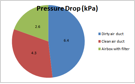
Stock intakes have 3 main components: the airbox & filter, the clean air duct between the airbox and compressor inlet, and the dirty air duct that sucks air from the fascia. You can actually divide up the total restriction in an intake system by running each piece on a flowbench at a specified airflow:
Aftermarket intakes for the FD stock turbos typically eliminate the airbox and dirty side air duct altogether. They replace the stock air filter with a less restrictive filter. However they leave the stock clean side duct, the hard pipe which runs to the compressor inlet. As this thread has observed, the rear Series 6 pipe very clearly has some kinks in it to meet some packaging constraints encountered at the time.
Having a lower restriction clean-side pipe for both turbos will help a given turbo breathe easier, and the turbo with the most kinked pipe will benefit the boost. It will run at lower pressure ratio to create a given amount of actual intake manifold boost. The tradeoff then is considering where the air would be drawn from, and the impact that would have on compressor outlet temperature (hotter inlet temperature = hotter outlet temperature). These details are a lot easier to work out with the right equipment: pressure and temperature measurements throughout the system, and a compressor wheel speed sensor.
TL;DRA less restrictive hard pipe to the inlet makes a turbo not work so hard, which is important when you are pushing the stock units, but you have to balance that with concerns about sucking in really hot air.
I love the setup on that one picture, looks like the housing has been clocked to allow for better inlet path design. Much smoother, I do see the kink on the J-spec version for the steering shaft.
I wish I had resources to create custom piping like that, then there's the tuning after all is said and done. Some BNR's added in would be killer but how does one go about improving exhaust flow or make an external wastegate?
On my car by getting cold ambient air to my intake made about a 30-40WHP (measured by injector duty cycle, not dyno) at same boost pressure.
This is on a single turbo 14-15PSI boost. I went from mid 40C air intake temps to 20C in same conditions.
20C difference roughly.
sometimes on cooler mornings I see single digit air temps 8C or so. I run a HUGE air filter.
same principals apply to the stock twins.
Before it starter snowing and I put my car to rest it did gain tremendous torque from the cold weather. I'm going to work on optimizing my intercooler, but linear flow is nice as well.
I want to size things properly and make them work, maybe once I get a Tig welder I can play a bit.
Before it starter snowing and I put my car to rest it did gain tremendous torque from the cold weather. I'm going to work on optimizing my intercooler, but linear flow is nice as well.
I want to size things properly and make them work, maybe once I get a Tig welder I can play a bit.
I suggest thinking about feeding your turbo's with cold air as first priority (outside of cooling the radiator). make a smaller intercooler and duct it will. duct has smaller opening than intercooler exchanger face.
we have gone pretty small on the intercooler and as long as you suck really cold air, the cars have made GREAT power gains.
We do have a welder in the springs area if you need a bunch of stuff welded, he is pretty good and affordable. I also tune powerFC's.
I'm pondering and a SMIC and BNR twins and perhaps shield the rear turbo from the exhaust a bit better. I can't wait for warmer weather so I can work on the FD and my e30 ls1
Yes and they changed the design for the rear turbo inlet pipe (rubber hose) and IC piping as well. I haven't seen the front turbo inlet piping but I have seen the updated primary elbow. OEM design for the 93-95 (in US) intake tract piping looks restrictive all around. If you replaced your IC then you only have to work on the turbo inlet piping. The JDM cars will have a steering shaft in the way probably greatly reducing the options for redesign on that pipe for JDM cars. USDM cars don't have the steering shaft constraint.
Nothing to do with the steering, more to do with firewall/transmission tunnel clearance....which affects both right and wrong steerers! Later primary elbow has a more pronounced taper and larger inlet diameter, I'm not sure it's hugely significant, just a pita when the rubber or silicon connector doesn't fit it - old one isn't available anymore afaik.
Meth injection is the best thing since sliced bread
Originally Posted by rxmiles
I'm pondering and a SMIC and BNR twins and perhaps shield the rear turbo from the exhaust a bit better. I can't wait for warmer weather so I can work on the FD and my e30 ls1


 .
.

 but it raises a good point.