
How to Test your solenoids, actuators, and other turbo stuff

Full Member
Joined: Jul 2010
Posts: 130
Likes: 0
From: sanger, california
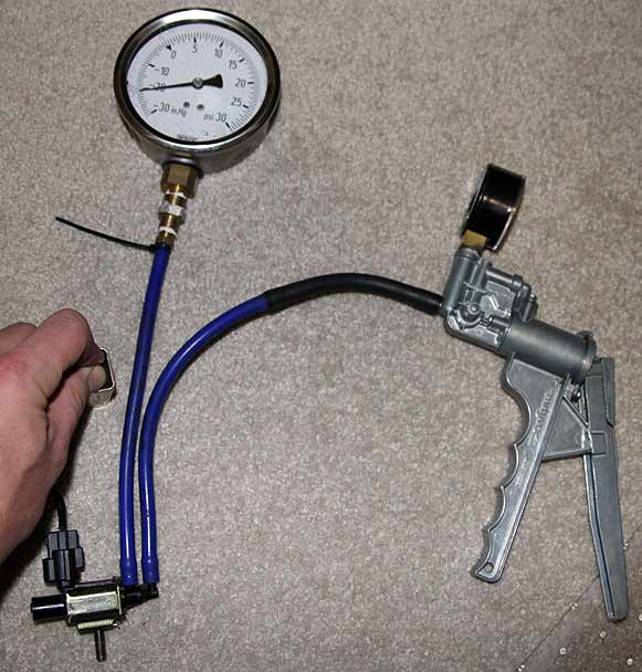
First, I'll test the basic rack solenoid.
Third, the energized leak test:
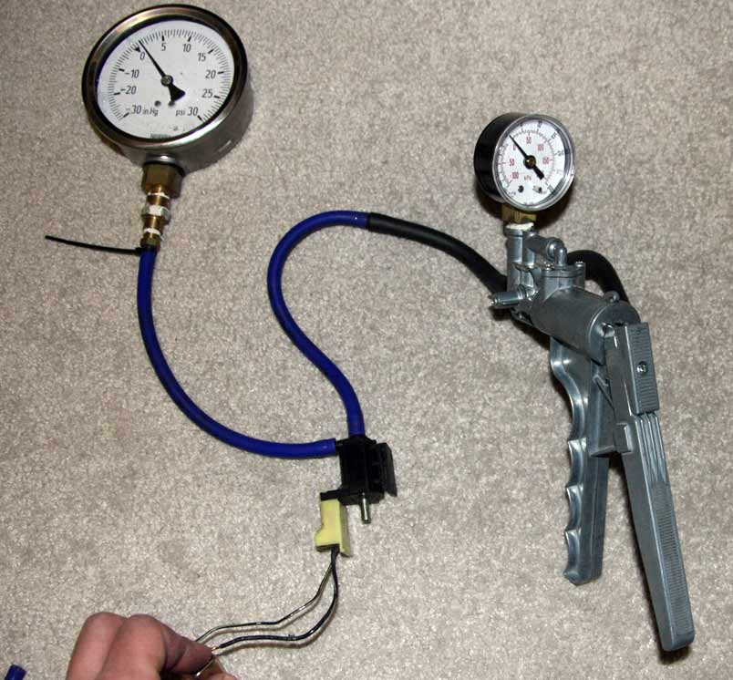
Set up like this, using your spare boost gauge or some other way to close off the output port of the solenoid. Just a section of hose with a golf tee in the end will work.
Connect the power source to the solenoid. It should click open immediately, and release immediately when the power is removed. I find that sometimes a solenoid that's been sitting on the shelf can stick, so you can give it a good rap and see if that gets it moving again. If a few taps doesn't get it moving freely, junk it.
This time keep the solenoid energized and apply full vacuum with the pump. If you have a boost gauge on the output end you should see it clearly. Now let it sit for a moment and see if it leaks. Junk it if it leaks. Now disconnect the power and see that the vacuum immediately vents through the dump port, and the vacuum isn't leaking at the source side. Junk it if it leaks (becoming a theme here?)
Repeat the energized test again, using pressure. I start with 12psi. Pay close attention this time to whether it releases immediately after disconnecting the power. If it hisses for a bit before snapping open, it's not a good thing. If it sticks and won't release, it's not good either. This means the spring is too weak or the plunger assembly is too gunked up to push the port open against the pressure. I like to repeat the test a few times until I figure out how of a pressure the solenoid can handle. If many of your solenoids don't pass this test but they pass the vacuum version of the tests, just be sure to only use them in a position where they will see only vacuum. I pick the solenoid that handles the highest pressure without sticking and use it as the turbo control solenoid.
Third, the energized leak test:
Set up like this, using your spare boost gauge or some other way to close off the output port of the solenoid. Just a section of hose with a golf tee in the end will work.
Connect the power source to the solenoid. It should click open immediately, and release immediately when the power is removed. I find that sometimes a solenoid that's been sitting on the shelf can stick, so you can give it a good rap and see if that gets it moving again. If a few taps doesn't get it moving freely, junk it.
This time keep the solenoid energized and apply full vacuum with the pump. If you have a boost gauge on the output end you should see it clearly. Now let it sit for a moment and see if it leaks. Junk it if it leaks. Now disconnect the power and see that the vacuum immediately vents through the dump port, and the vacuum isn't leaking at the source side. Junk it if it leaks (becoming a theme here?)
Repeat the energized test again, using pressure. I start with 12psi. Pay close attention this time to whether it releases immediately after disconnecting the power. If it hisses for a bit before snapping open, it's not a good thing. If it sticks and won't release, it's not good either. This means the spring is too weak or the plunger assembly is too gunked up to push the port open against the pressure. I like to repeat the test a few times until I figure out how of a pressure the solenoid can handle. If many of your solenoids don't pass this test but they pass the vacuum version of the tests, just be sure to only use them in a position where they will see only vacuum. I pick the solenoid that handles the highest pressure without sticking and use it as the turbo control solenoid.
"Connect the power source to the solenoid. It should click open immediately, and release immediately when the power is removed."
"Repeat the energized test again, using pressure. I start with 12psi. Pay close attention this time to whether it releases immediately after disconnecting the power."
It doesnt make sense to me because it should releases immediately after connecting the power to the solenoid not when you disconnecting or remove the power from the solenoid.
I just got done testing a few of my solenoids and they are all holding the max vacuum and psi when there is no power connected to them. However, once I connect power to the solenoids (while still holding max vacuum or psi) they release the vacume and or psi.
To me it seems like it should be the other way around when your adding power to the solenoid...
"Connect the power source to the solenoid. It should click open immediately, and release immediately when the power is removed."
"Repeat the energized test again, using pressure. I start with 12psi. Pay close attention this time to whether it releases immediately after disconnecting the power."
It doesnt make sense to me because it should releases immediately after connecting the power to the solenoid not when you disconnecting or remove the power from the solenoid.
I just got done testing a few of my solenoids and they are all holding the max vacuum and psi when there is no power connected to them. However, once I connect power to the solenoids (while still holding max vacuum or psi) they release the vacume and or psi.
This is what all my solenoids are doing also. I apply vacuum to port A while capping port B with no power and they hold max psi. When I connect power to the solenoid it opens and releases the pressure. One other thing do you check them with vacuum or pressure? Here is a test done with pressure not vacuum. http://rx7.voodoobox.net/howto/solen...oid_check.html
So if any one can help with this please do. The question is are the solenoids suppose to hold pressure when energized or when not energized? Also do you use vacuum or pressure to test them?


When I re-read my original post I don't think I wrote incorrectly.
I repeat this test using both vacuum and pressure.
Because you're connecting the Mityvac to the port that's only open to the to output under power, you need to energize it to pump vacuum or pressure to the output side. It should hold whatever pressure (or vacuum) you've applied. Then the real test is what happens when you take off the power - the solenoid should dump the pressure trapped on the output side (the side with the big pressure gauge). A good solenoid has a strong enough plunger spring and will dump the pressure to the open port almost instantly. A not-so-good solenoid will hiss for a moment or two before dumping pressure. Less good is when it just sticks. I repeat this test several times with different pressures to determine at what pressure the solenoid no longer releases cleanly.
Hopefully I've clarified things.
I wanted to add something that I didn't find for testing the Charge Control Actuator. I found that all the testing procedures don't show a complete way of testing it properly.
Every guide shows you that all you need to do is hook up a vacuum pump to the nipple that connects to the LIM (solenoid), apply vacuum, and the valve should be pulled in (closed), then you remove the vacuum line, and the arm should pop back out (open).
Well the problem I found is that even if the vacuum side is working properly, the CCA also has the pressure side which is the hose connected directly to the y-pipe. The pressure side also needs to be tested in the same manner as the vacuum side (using pressure instead) because the CCA valve is supposed to open when the pressure and vacuum inside the CCA are equal to each other.
The ideal way the CCA should be tested, is to hook up (2) pumps, 1 applying vacuum to the top end, and 1 applying pressure to the bottom end. Then you apply the same quantity of pressure and vacuum and then the CCA valve should open (pop out), and whenever the pressure/vacuum is uneven, the CCA should remain closed (pulled in). Obviously with no leaks.
Junior Member
Joined: Nov 2010
Posts: 11
Likes: 0
From: Sydney, Australia
Sorry to bring up an old thread, but the turbo control (vacuum) solenoid. I've tested it with my multi meter across the prongs and there's no reading at all. It's not reading 0.01 ohms, it's not reading 38ohms, it's not reading 80ohms. Just no reading at all, any advice?
So the multimeter is showing an open circuit? As long as you are sure the meter is good and you have a good connection to the prongs (i.e. no corrosion). I'd say you need to change the solenoid, it is bad.
John
John

Full Member
Joined: Jun 2004
Posts: 99
Likes: 0
From: f
Well, no, if I put the pos and neg prongs of the multimeter together i'll get something like 0.001ohms, but if i place it on the solenoid prongs, nothing registers or changes in the multimeter reading, it's like i did nothing at all. It just displays the decimal point to indicate the scale it's on.
That's not an open circuit is it? That'd be the opposite a totally closed circuit with nothing getting through right?
[edit] sorry got 2 accounts here
That's not an open circuit is it? That'd be the opposite a totally closed circuit with nothing getting through right?
[edit] sorry got 2 accounts here

Senior Member
Joined: May 2001
Posts: 297
Likes: 0
From: laurel, md usa
Sorry to bring up an old thread, but the turbo control (vacuum) solenoid. I've tested it with my multi meter across the prongs and there's no reading at all. It's not reading 0.01 ohms, it's not reading 38ohms, it's not reading 80ohms. Just no reading at all, any advice?
Where Is the ground point for the solenoids? the one under the coils? wasn't getting continuity there.
Advance Auto had a brake bleeder loaner tool that does pressure too "PowerBuilt" brand.
Found 2 solenoids that did not open after baking on the lowest settings on my toaster oven. they worked again when they cooled down, may test again at higher temps.
At 20-25 psi and 175-200F the rack solenoids held and opened.
Turbo Control (Vacuum) solenoid, how much pressure are you guys getting to hold on port B?
Tested a new one and it is holding about 3-5 psi. (difficult to read the gauge when its close to zero). haven't analyzed whether port b may see those pressures.


I'm not sure where the ground point is for the solenoids. A look at the wiring diagram and you should be able to figure it out. As for the turbo control solenoid, I believe all solenoids should be capable of vacuum at 24" and boost at 14 psi.

I talked to one of the senior techs at Pettit about the charge control valve. He said the actuator should not leak vacuum at all but it is normal for pressure to leak out of the shaft on port B.
I also went through 3 TC Vacuum solenoids from Malloy and all had a very slow leak (10seconds drops 1psi). He said its fine and normal as well.
I also went through 3 TC Vacuum solenoids from Malloy and all had a very slow leak (10seconds drops 1psi). He said its fine and normal as well.
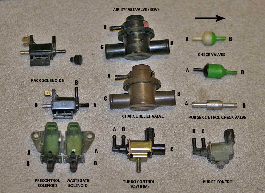
This is the solenoid that mounts onto the ACV.
It looks like a purge control solenoid but it's not the same thing. That plastic cap on the end actually covers the dump port (pull it off if you're curious), at which point you can clearly see this is a 3-way valve.
It operates by switching vacuum. It opens and closes exactly with the turbo control (pressure) solenoid in the rack, in fact the wiring joins within the harness and is controlled by one pin on the ECU. One applies pressure to one side of the actuator, the other applies vacuum to the opposite side. I suspect this is because the spring in the actuator is much stiffer than the others.
Set up like this, with a dead-end on port B and your vacuum pump on port A.
Just like a rack solenoid, test to see that it does not leak with 25" vacuum. Then energize it and see that it opens cleanly and again the vacuum does not leak.
Coil resistance should be about 37 Ohms.
There is no coverage for this solenoid in the FSM. I believe Mazda added it at the last minute to improve the response of the turbo control actuator.
I just did the test on this turbo control vacuum solenoid brand new from Malloy with 9v battery and mityvac. what I realized was if I left the port B open, 25inHg of vacuum did not leak from port A when no power is applied for the basic leak test. Is this a problem?
when I capped port B and connect the battery to the terminals to release the vacuum from port A, I can hear the plunger move, but 1inHg of vacuum leaks from port A every time I tap the battery to energize the solenoid.
anyone having the same testing results?
Exhaust Manifold Leak

Joined: Jun 2005
Posts: 815
Likes: 42
From: western europe
I talked to one of the senior techs at Pettit about the charge control valve. He said the actuator should not leak vacuum at all but it is normal for pressure to leak out of the shaft on port B.
I also went through 3 TC Vacuum solenoids from Malloy and all had a very slow leak (10seconds drops 1psi). He said its fine and normal as well.
I also went through 3 TC Vacuum solenoids from Malloy and all had a very slow leak (10seconds drops 1psi). He said its fine and normal as well.
it halso had a slightly leaking check valve to the pressure tank above 0.5 bar. the turbo control vacuum side solenoid (the one on the ACV) worked fine when cold, but not when hot, there was a leaking vac hose going to the rear turbo bypass valve and half of the rack solenoids leaked when apllying pressure. Also the actuator off the flap in the rear turbos compressor exit was going not smooth, it didnt release well after taking the vacuum away. I cleaned it with brake cleaner and sprayed it with PTFE dry lube, now it goes smooth again!
Suprisingly I could somethimes still make it boost nice, but 95% of the time poor boost on the primary and no secondary boost.
Exhaust Manifold Leak
Joined: Jun 2005
Posts: 815
Likes: 42
From: western europe
now it boosts fine but doesnt rev over 5000 rpm 95% of the time, its a JSpec car and it just feels the same like the speed limiter at 180 kph. what it strange now is that the mileage digital indicator in the speedometer doest not work anymore, but tacho and speedo is working fine.
I check and the ground to the UIM is connected.
I removed the ACV and all this piping from the airpump, also removed the double throttle vacuum hoses, but I left al the solenoids connected electrically and also the airpump is still there and connected to the wiring harness. below 3000 rpm it now bucks and backfires
another strange thing is that it lights the CEL with ign on, but not at idle, even when i disconnect a sensor, like IAT or MAP sensor, it does not blink the CEL when connecting this TEN terminal to ground.
Damn FD's
Exhaust Manifold Leak
Joined: Jun 2005
Posts: 815
Likes: 42
From: western europe
Also it did not want to drive in light load, it would just cut out like a fuel cut.. I replaced the stock ecu with a re amaiya B type, all problems away now, drives smooth down low and pulls fine till redline. also boost pattern is really good. only issue is still when flooring in the middle of the transistion, lets say 4000 rpm, boost built up is a bit sluggish.. also it has the normal hickup at 3000 rpm tip in that most fd's have..
first off, dgeesaman, thank-you for the write-up. it is greatly appreciated.
testing my solenoids for the first time, and i'm trying to figure if it's just me, or are there some typos or mistakes in this write up.
i'm looking at the original picture, where you have the rack solenoid labeled (C) on the left side, (B) on the top and (A) on the right side.
then you state that each solenoid has a source port (A), a dump port (C), and an outpout port (B)
then for the basic leak test, you say to apply full vacuum and full pressure to the output port.
but in the picture, you are applying it to (A), which is the source port, according to the info above.
then for the third test (energized leak test), you show the mityvac connected to (A)(source port), and the boost gauge/cap on (b)(output port)

+3
^this is exactly what is happening when I am testing. when I add the 12V, it releases the vacuum/pressure.
what are we doing wrong here? I tested 10 solenoids and they all acted the same in this regard.
thanks,
Ben
testing my solenoids for the first time, and i'm trying to figure if it's just me, or are there some typos or mistakes in this write up.
i'm looking at the original picture, where you have the rack solenoid labeled (C) on the left side, (B) on the top and (A) on the right side.
then you state that each solenoid has a source port (A), a dump port (C), and an outpout port (B)
but in the picture, you are applying it to (A), which is the source port, according to the info above.
then for the third test (energized leak test), you show the mityvac connected to (A)(source port), and the boost gauge/cap on (b)(output port)
To me it seems like it should be the other way around when your adding power to the solenoid...
"Connect the power source to the solenoid. It should click open immediately, and release immediately when the power is removed."
"Repeat the energized test again, using pressure. I start with 12psi. Pay close attention this time to whether it releases immediately after disconnecting the power."
It doesnt make sense to me because it should releases immediately after connecting the power to the solenoid not when you disconnecting or remove the power from the solenoid.
I just got done testing a few of my solenoids and they are all holding the max vacuum and psi when there is no power connected to them. However, once I connect power to the solenoids (while still holding max vacuum or psi) they release the vacume and or psi.
"Connect the power source to the solenoid. It should click open immediately, and release immediately when the power is removed."
"Repeat the energized test again, using pressure. I start with 12psi. Pay close attention this time to whether it releases immediately after disconnecting the power."
It doesnt make sense to me because it should releases immediately after connecting the power to the solenoid not when you disconnecting or remove the power from the solenoid.
I just got done testing a few of my solenoids and they are all holding the max vacuum and psi when there is no power connected to them. However, once I connect power to the solenoids (while still holding max vacuum or psi) they release the vacume and or psi.
+2
This is what all my solenoids are doing also. I apply vacuum to port A while capping port B with no power and they hold max psi. When I connect power to the solenoid it opens and releases the pressure. One other thing do you check them with vacuum or pressure? Here is a test done with pressure not vacuum. Solenoid Check
So if any one can help with this please do. The question is are the solenoids suppose to hold pressure when energized or when not energized? Also do you use vacuum or pressure to test them?
^this is exactly what is happening when I am testing. when I add the 12V, it releases the vacuum/pressure.
what are we doing wrong here? I tested 10 solenoids and they all acted the same in this regard.
thanks,
Ben
Sorry for not checking in on this thread and fixing this earlier.
I have now corrected that, thank you.
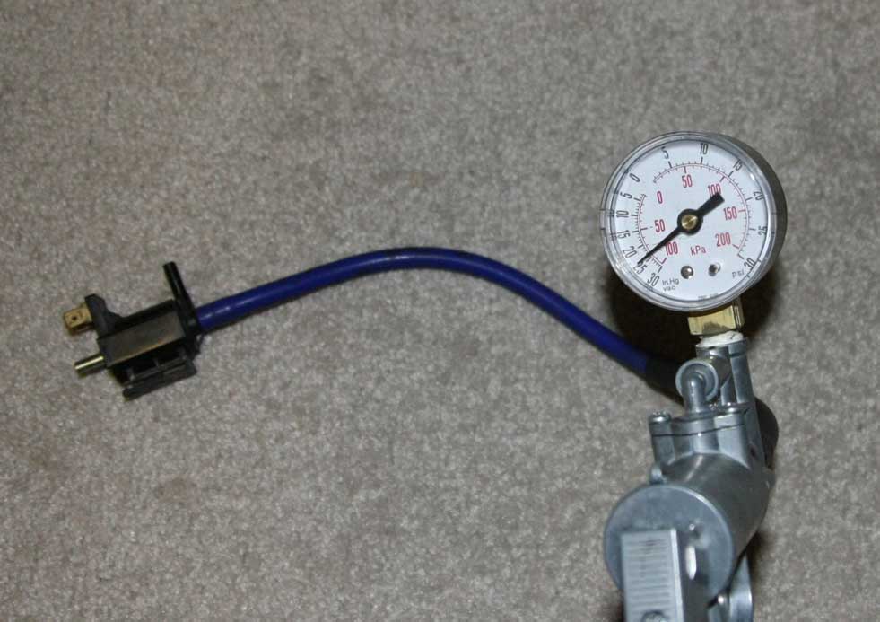
In this arrangement, we're testing two things at once. First, we pressure A, which should go nowhere if the solenoid is not energized.
Next, we apply power, which switches port B to A. The boost gauge on B should show nearly the same value as the Mityvac, with a reduction due to filling the larger volume. This "loads" the output port, as it would when the actuator is being driven. Pump up to whatever pressure you intend to test.
Now the stricter part of the test: remove power, allowing the internal plunger to drive toward A and switch the connection of B from A to C and releasing the pressure that was stored in B. The Mityvac should not lose pressure. If the solenoids internal plunger does not manage this cleanly you get poor turbo response. Many solenoids don't do this well, and few can reliably switch against 10 or 12psi of backpressure.
If the solenoid releases, and you connect power again, the remaining pressure in the Mityvac will pressurize B again. It will admit to "playing" like this and hearing the click and hiss, but after the first power cycle you're only repeating what you've already done.
Does that help?
I might be able to do a short video clip.
David
then for the third test (energized leak test), you show the mityvac connected to (A)(source port), and the boost gauge/cap on (b)(output port)
Originally Posted by mainboyd View Post
To me it seems like it should be the other way around when your adding power to the solenoid...
"Connect the power source to the solenoid. It should click open immediately, and release immediately when the power is removed."
"Repeat the energized test again, using pressure. I start with 12psi. Pay close attention this time to whether it releases immediately after disconnecting the power."
^this is exactly what is happening when I am testing. when I add the 12V, it releases the vacuum/pressure.
what are we doing wrong here? I tested 10 solenoids and they all acted the same in this regard.
thanks,
Ben
Originally Posted by mainboyd View Post
To me it seems like it should be the other way around when your adding power to the solenoid...
"Connect the power source to the solenoid. It should click open immediately, and release immediately when the power is removed."
"Repeat the energized test again, using pressure. I start with 12psi. Pay close attention this time to whether it releases immediately after disconnecting the power."
It doesnt make sense to me because it should releases immediately after connecting the power to the solenoid not when you disconnecting or remove the power from the solenoid.
I just got done testing a few of my solenoids and they are all holding the max vacuum and psi when there is no power connected to them. However, once I connect power to the solenoids (while still holding max vacuum or psi) they release the vacume and or psi.
I just got done testing a few of my solenoids and they are all holding the max vacuum and psi when there is no power connected to them. However, once I connect power to the solenoids (while still holding max vacuum or psi) they release the vacume and or psi.
what are we doing wrong here? I tested 10 solenoids and they all acted the same in this regard.
thanks,
Ben
Next, we apply power, which switches port B to A. The boost gauge on B should show nearly the same value as the Mityvac, with a reduction due to filling the larger volume. This "loads" the output port, as it would when the actuator is being driven. Pump up to whatever pressure you intend to test.
Now the stricter part of the test: remove power, allowing the internal plunger to drive toward A and switch the connection of B from A to C and releasing the pressure that was stored in B. The Mityvac should not lose pressure. If the solenoids internal plunger does not manage this cleanly you get poor turbo response. Many solenoids don't do this well, and few can reliably switch against 10 or 12psi of backpressure.
If the solenoid releases, and you connect power again, the remaining pressure in the Mityvac will pressurize B again. It will admit to "playing" like this and hearing the click and hiss, but after the first power cycle you're only repeating what you've already done.
Does that help?
I might be able to do a short video clip.
David
Last edited by dgeesaman; Mar 9, 2014 at 05:51 PM.

Senior Member
Joined: Jan 2004
Posts: 505
Likes: 2
From: New Orleans, LA
Wow!!! This is such great information! I am going to do all of this. I replaced all of my vacuum lines on my rats nest an my car already runs so much better. But I was wondering about all the the valves etc. can't wait to test it all. Thank you so much for this information. You rock!
Joined: Jan 2002
Posts: 922
Likes: 0
From: KC, KS
I just ordered the pump kit and an extra gauge from Amazon.
Has anyone found a reliable system for power? I saw in the previous posts someone modified a computer power supply but didn't give details on wattage, which wires to use, etc. A 9V battery does not seem to be reliable for testing based on thread comments.
Has anyone found a reliable system for power? I saw in the previous posts someone modified a computer power supply but didn't give details on wattage, which wires to use, etc. A 9V battery does not seem to be reliable for testing based on thread comments.

Joined: Jan 2002
Posts: 922
Likes: 0
From: KC, KS
