
How the FD anti-lock brakes (ABS) is controlled


How the FD anti-lock brakes (ABS) is controlled
Outline
The FD uses a basic 3-channel anti-lock brake system that was common in that period. By utilizing wheel speed sensors the ABS system can regulate the hydraulic pressure to the wheels in order to prevent a lock-up situation. Below is a basic diagram of the ABS system from the Service Highlights document:
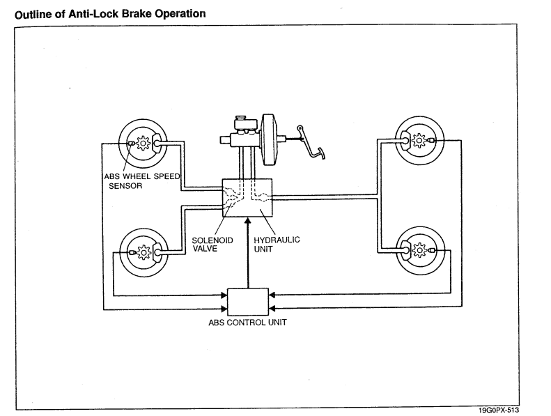
Each wheel has a speed sensor that relays information to the control unit. The control unit operates the 3 solenoids and pump contained in the hydraulic unit,. The front wheels have their own individual solenoid and the two rear wheels have one solenoid, hence a 3-channel system. More modern designs use individual control of all four wheels ('99 spec uses a 4 channel design). The solenoids' job is to increase, reduce, or retain hydraulic pressure according to commands from the control unit. The pump returns fluid to the reservoir while the ABS system is in operation.
Control strategy
It's important to recognize that ABS systems and basic traction control systems are actually closely related in the concept of their operation. Controlling either system requires the calculation of a wheel slip ratio. A slip ratio is the relationship between the speed of the vehicle and the speed of the individual wheel. It can be calculated by:
(vehicle speed - wheel speed) / vehicle speed
You can set up signs (+ or -) in the calculation such that a braking slip (leading to a locked tire) has a negative sign and positive slip (roasting the tires due to wheelspin) has a positive sign. Here is a diagram from a paper on the C4 Corvette ABS & traction control system which illustrates this concept:
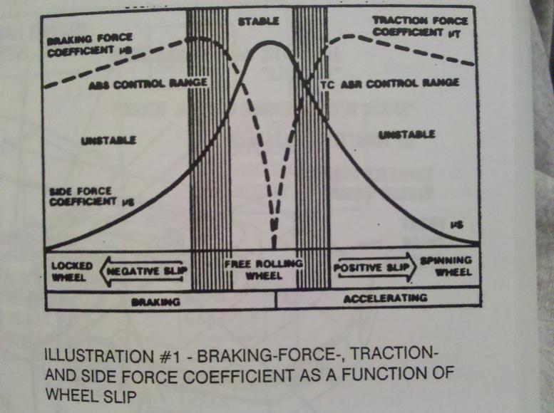
Both ABS and traction control systems seek to keep the slip ratio within a range that maintains performance and control of the vehicle. On an ABS system the solenoids regulate the hydraulic pressure to the brakes, while on a traction control system various methods are employed to reduce engine output.
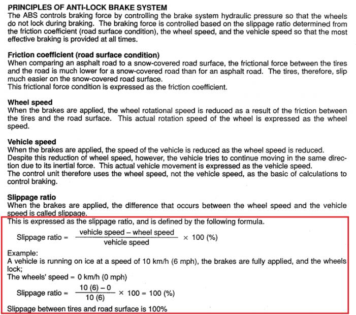
An FD doesn't have a traction control system. When the FD control unit calculates wheel slip it doesn't seem to differentiate between negative slip (during deceleration) and positive slip (during acceleration). Here's Mazda's calculation right out of the service highlights:
The control range for the FD is between 8 and 30% slip ratio according to Mazda, which is similar to other manufacturers' systems.
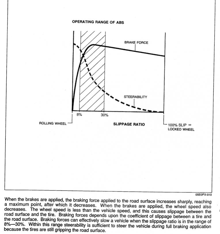
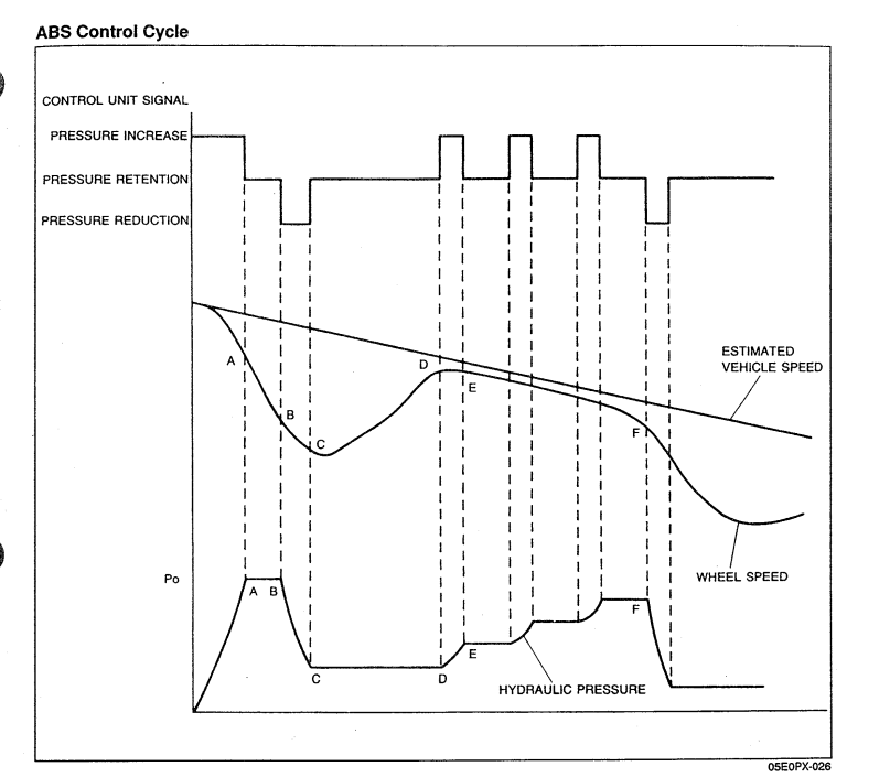
To stay within this range, the ABS system cycles the hydraulic pressure to the wheels. This contributes to the pulsation felt during ABS operation.
Again, an ABS and a traction control system are similar in concept. On a traction control system the ECU will manipulate ignition timing, throttle position, and fuel injection to reduce engine output. Older cars from the era of the FD may have rather complicated system control modules and actuators to accomplish this. More modern systems, such as those found on the Rx-8, implement traction control functionality through an electronic throttle and a series of commands sent to control modules on a serial network.
There has been some discussion in the past as to whether changing the wheels could affect ABS performance. I can't say I've really done a meaningful test of this in the real world. However it is conceivable that changing the overall diameter of wheel + tire could affect ABS behavior by changing the wheel speed reading used for slip ratio calculations. Using a wheel/tire calculator can help get an idea of whether the overall diameter will change significantly http://www.miata.net/garage/tirecalc.html
Other Vehicle Dynamics Systems
So what vehicle dynamics technology does the FD lack compared to newer cars?
-- Vehicles with stability control calculate the yaw rates to figure out oversteer and understeer. Based on these calculations the system applies brakes (through the ABS system) to individual wheels and/or cut engine power to stabilize the yaw rate into a controllable range.
-- Vehicles with torque vectoring differentials will distribute power to individual wheels (and axles in the case of AWD) to help the car get through a turn with maximum speed while avoiding instability. The computer will calculate how to distribute torque to the drive wheels instead of being limited by the mechanical design of the differential.
-- A vehicle with electronic brakeforce distribution uses the ABS solenoids to divide brake pressure between the front and rear in response to vehicle conditions (calculated friction on the tires). This supplements or eliminates the traditional brake proportional valve.
An advanced modern car like an R35 GT-R or Evo X incorporates all of those systems. Due to upcoming safety laws new passenger cars in the US will be implementing stability control systems.
The FD uses a basic 3-channel anti-lock brake system that was common in that period. By utilizing wheel speed sensors the ABS system can regulate the hydraulic pressure to the wheels in order to prevent a lock-up situation. Below is a basic diagram of the ABS system from the Service Highlights document:
Each wheel has a speed sensor that relays information to the control unit. The control unit operates the 3 solenoids and pump contained in the hydraulic unit,. The front wheels have their own individual solenoid and the two rear wheels have one solenoid, hence a 3-channel system. More modern designs use individual control of all four wheels ('99 spec uses a 4 channel design). The solenoids' job is to increase, reduce, or retain hydraulic pressure according to commands from the control unit. The pump returns fluid to the reservoir while the ABS system is in operation.
Control strategy
It's important to recognize that ABS systems and basic traction control systems are actually closely related in the concept of their operation. Controlling either system requires the calculation of a wheel slip ratio. A slip ratio is the relationship between the speed of the vehicle and the speed of the individual wheel. It can be calculated by:
(vehicle speed - wheel speed) / vehicle speed
You can set up signs (+ or -) in the calculation such that a braking slip (leading to a locked tire) has a negative sign and positive slip (roasting the tires due to wheelspin) has a positive sign. Here is a diagram from a paper on the C4 Corvette ABS & traction control system which illustrates this concept:
Both ABS and traction control systems seek to keep the slip ratio within a range that maintains performance and control of the vehicle. On an ABS system the solenoids regulate the hydraulic pressure to the brakes, while on a traction control system various methods are employed to reduce engine output.
An FD doesn't have a traction control system. When the FD control unit calculates wheel slip it doesn't seem to differentiate between negative slip (during deceleration) and positive slip (during acceleration). Here's Mazda's calculation right out of the service highlights:
The control range for the FD is between 8 and 30% slip ratio according to Mazda, which is similar to other manufacturers' systems.
To stay within this range, the ABS system cycles the hydraulic pressure to the wheels. This contributes to the pulsation felt during ABS operation.
Again, an ABS and a traction control system are similar in concept. On a traction control system the ECU will manipulate ignition timing, throttle position, and fuel injection to reduce engine output. Older cars from the era of the FD may have rather complicated system control modules and actuators to accomplish this. More modern systems, such as those found on the Rx-8, implement traction control functionality through an electronic throttle and a series of commands sent to control modules on a serial network.
There has been some discussion in the past as to whether changing the wheels could affect ABS performance. I can't say I've really done a meaningful test of this in the real world. However it is conceivable that changing the overall diameter of wheel + tire could affect ABS behavior by changing the wheel speed reading used for slip ratio calculations. Using a wheel/tire calculator can help get an idea of whether the overall diameter will change significantly http://www.miata.net/garage/tirecalc.html
Other Vehicle Dynamics Systems
So what vehicle dynamics technology does the FD lack compared to newer cars?
-- Vehicles with stability control calculate the yaw rates to figure out oversteer and understeer. Based on these calculations the system applies brakes (through the ABS system) to individual wheels and/or cut engine power to stabilize the yaw rate into a controllable range.
-- Vehicles with torque vectoring differentials will distribute power to individual wheels (and axles in the case of AWD) to help the car get through a turn with maximum speed while avoiding instability. The computer will calculate how to distribute torque to the drive wheels instead of being limited by the mechanical design of the differential.
-- A vehicle with electronic brakeforce distribution uses the ABS solenoids to divide brake pressure between the front and rear in response to vehicle conditions (calculated friction on the tires). This supplements or eliminates the traditional brake proportional valve.
An advanced modern car like an R35 GT-R or Evo X incorporates all of those systems. Due to upcoming safety laws new passenger cars in the US will be implementing stability control systems.
In terms of the basic control logic I suspect the ABS systems vary by series rather than say USDM vs another market. The later cars had different tire sizes for example, and I've read that the series 8 cars had a 4 channel system with individual control of the rear wheels. There may be some differences specifically related to lefthand vs righthand drive.

Batman
Joined: Jun 2011
Posts: 53
Likes: 0
From: Tasmania, Australia
Thanks for the writeup. That was a really good post.
One thing though, is it possible to change the 8-30% slippage ratio into mph/kmh values by working backwards or something?
The example above gives ice driving at 10kmh, and the wheels lock up.
And their formula says: 10-0 /10 x100 = 100% slip ratio value (IE 100 being "Oh **** we're sliding towards that minivan and have no control whatsoever)
So what would 8% be? 30%?
I'm just interested to know figures on the limits of the system. I assume 8% is the slowest speed the system will work, and 30% being maximum?
Thanks for the writeup. That was a really good post.
One thing though, is it possible to change the 8-30% slippage ratio into mph/kmh values by working backwards or something?
The example above gives ice driving at 10kmh, and the wheels lock up.
And their formula says: 10-0 /10 x100 = 100% slip ratio value (IE 100 being "Oh **** we're sliding towards that minivan and have no control whatsoever)
So what would 8% be? 30%?
IF vehicle speed is 10 km/h , then 30% slip ratio would require a wheel speed of 7 km/h. (10-7)/10 = 3 which works out to 30%. Again it depends how you set it up mathematically. Basically it's a % difference formula. Plug 10 and 7 into this % difference calculator and it will make sense http://www.calculatorsoup.com/calcul...tagechange.php
If you start plugging numbers into that calculator you can begin to see the mathematical relationship. Keep "v1" (the vehicle speed) the same and change "v2" (the wheel speed) a few times. At a given vehicle speed, a higher wheel speed results in a lower slip ratio. Now do the opposite: change "v1" (vehicle speed) and keep "v2" the same. At a given wheel speed, a higher vehicle speed results in a higher slip ratio.
I'm just interested to know figures on the limits of the system. I assume 8% is the slowest speed the system will work, and 30% being maximum?[/QUOTE]
Using our example of a vehicle speed at 10 km/h, the ABS system will try to keep the wheel speed between 9.2 km/h (8% slip ratio) and 7 km/h (30%) slip ratio. I'm sure there is a basic feedback system inside the computer to keep it within that range.
The ABS system also estimates how much friction is between the individual tires and the ground. The whole point of that is to figure out whether one or two wheels is on say ice while the others are on dry pavement. This affects the distribution of the braking pressure, to keep the vehicle from going into a skid. Remember that you have an interaction between the anti-lock braking system and the differential.
There is a whole science between making the differential and the ABS/driving dynamics systems work together. The series 6 FD, being an older system, is particularly limited in how it can make those two systems work together (on paper at least). This is because the differential is limited by its preload and "bias ratio," which are ways it is mechanically designed to transfer torque from the wheel with high traction to the wheel with lower traction. The 3 channel system also limits the system because it does not have individual wheel control on that same axle which has a differential. All of this is completely normal for an early 90s car though.
Their example is made extremely simple to illustrate the concept.
Answering this requires you to understand the basic nature of the mathematical relationship and it requires you to recall some highschool math. I'll start by directly answering your question.
IF vehicle speed is 10 km/h , then 30% slip ratio would require a wheel speed of 7 km/h. (10-7)/10 = 3 which works out to 30%. Again it depends how you set it up mathematically. Basically it's a % difference formula. Plug 10 and 7 into this % difference calculator and it will make sense http://www.calculatorsoup.com/calcul...tagechange.php
If you start plugging numbers into that calculator you can begin to see the mathematical relationship. Keep "v1" (the vehicle speed) the same and change "v2" (the wheel speed) a few times. At a given vehicle speed, a higher wheel speed results in a lower slip ratio. Now do the opposite: change "v1" (vehicle speed) and keep "v2" the same. At a given wheel speed, a higher vehicle speed results in a higher slip ratio.
I'm just interested to know figures on the limits of the system. I assume 8% is the slowest speed the system will work, and 30% being maximum?
Using our example of a vehicle speed at 10 km/h, the ABS system will try to keep the wheel speed between 9.2 km/h (8% slip ratio) and 7 km/h (30%) slip ratio. I'm sure there is a basic feedback system inside the computer to keep it within that range.
The ABS system also estimates how much friction is between the individual tires and the ground. The whole point of that is to figure out whether one or two wheels is on say ice while the others are on dry pavement. This affects the distribution of the braking pressure, to keep the vehicle from going into a skid. Remember that you have an interaction between the anti-lock braking system and the differential.
There is a whole science between making the differential and the ABS/driving dynamics systems work together. The series 6 FD, being an older system, is particularly limited in how it can make those two systems work together (on paper at least). This is because the differential is limited by its preload and "bias ratio," which are ways it is mechanically designed to transfer torque from the wheel with high traction to the wheel with lower traction. The 3 channel system also limits the system because it does not have individual wheel control on that same axle which has a differential. All of this is completely normal for an early 90s car though.

Im debating removing the ABS from the FD I'm actually still on the bounds But this thread has shed alot of light onto the subject . But now
The slippage rate of 8-30 % is that determined by pedal pressure coming form the driver? say 8% being at full pressure , and 30% being at 3/4 pressure? or is that just a margin that hte ABS works at ? I'm still trying to make sense of the charts you put so i'm sorry if the answer is in one of them
Last edited by Tem120; Nov 24, 2011 at 10:21 PM.
Trending Topics
Batman
Joined: Jun 2011
Posts: 53
Likes: 0
From: Tasmania, Australia
Thanks to Arghx for the simplified explanation. That explained exactly what I wanted to know 
Tem120, I think (and arghx will correct me if I'm wrong) that the 8-30% is the working margin for the system. As was mentioned in the first post, it was normal for cars of the early 90's era to use roughly the 8-30% margin in their ABS systems. I think the graph shows that during this spread, the steering is still responsive, and thus that makes me think that they chose this margin to give the driver best control under brakes.
Tem120, I think (and arghx will correct me if I'm wrong) that the 8-30% is the working margin for the system. As was mentioned in the first post, it was normal for cars of the early 90's era to use roughly the 8-30% margin in their ABS systems. I think the graph shows that during this spread, the steering is still responsive, and thus that makes me think that they chose this margin to give the driver best control under brakes.
Thanks to Arghx for the simplified explanation. That explained exactly what I wanted to know
Tem120, I think (and arghx will correct me if I'm wrong) that the 8-30% is the working margin for the system. As was mentioned in the first post, it was normal for cars of the early 90's era to use roughly the 8-30% margin in their ABS systems. I think the graph shows that during this spread, the steering is still responsive, and thus that makes me think that they chose this margin to give the driver best control under brakes.
Tem120, I think (and arghx will correct me if I'm wrong) that the 8-30% is the working margin for the system. As was mentioned in the first post, it was normal for cars of the early 90's era to use roughly the 8-30% margin in their ABS systems. I think the graph shows that during this spread, the steering is still responsive, and thus that makes me think that they chose this margin to give the driver best control under brakes.

Tem120, I think (and arghx will correct me if I'm wrong) that the 8-30% is the working margin for the system. As was mentioned in the first post, it was normal for cars of the early 90's era to use roughly the 8-30% margin in their ABS systems. I think the graph shows that during this spread, the steering is still responsive, and thus that makes me think that they chose this margin to give the driver best control under brakes.
The slip calculations as well as tire-road friction calculations (which are a lot more complicated) are used in basically every type of vehicle dynamics system. On a Subaru AWD system for example the computer will estimate friction between the tire and whatever surface it's on in order to determine the torque split between the front and rear axle. These more sophisticated drivetrains distribute braking and engine torque to individual wheels based on various calculations. The overall benefit of these systems is hard to argue with but they understandably tend to attract criticism from purists. I appreciate the driving experience of a "raw" car without very little aids, but I also appreciate the engineering involved in vehicle dynamics systems.
Originally Posted by Tem120
Now 30% marginseems like alot , I just want to know if this is a margin triggered by certain circumstances or just random luck of the draw at the certain moment , say if for the first couple of laps its working at 8 % and you get used to this breaking point , then you get a 30% and overshoot because the ABS .. OR is there any way to trigger , reduce the slip allowed by the ABS?

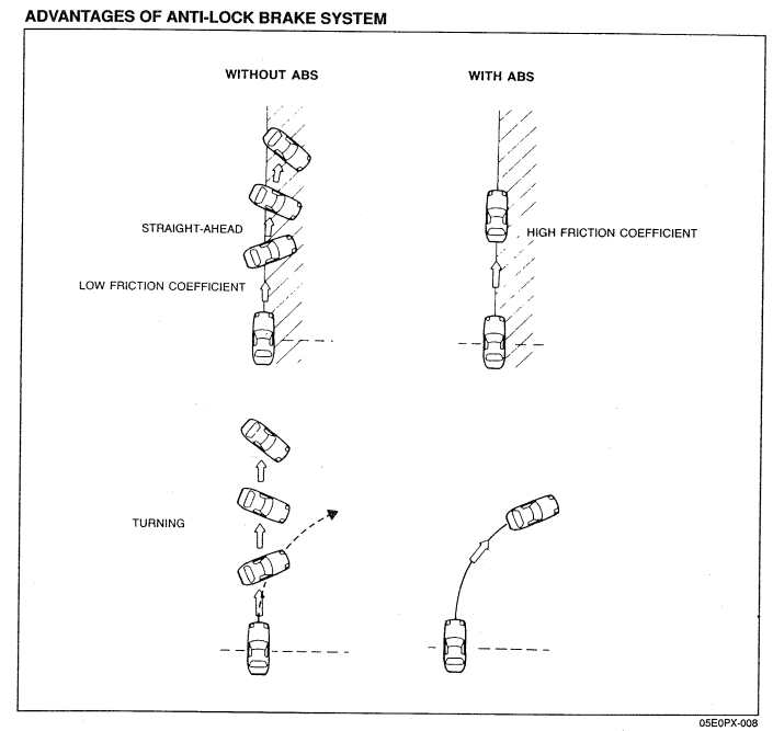
I want to clarify and emphasize one point. Yes, the FD ABS system is out dated compared to systems on even the most mundane modern vehicles. Yes, a good driver in a vehicle without ABS has good control over the brake pedal. Yet the main purpose of ABS is to prevent loss of control when one side of the vehicle has more traction than the other during braking. So if you hit a puddle of water on the passenger side while braking, it will prevent one or two wheels from locking up. That lockup can make the car spin out of control.
There are certain situations where no amount of driver skill can somehow replace ABS functionality. If you're driving around in the dark, you hit some black ice while braking into a turn, you can't selectively brake one wheel. Only ABS can do that. Without ABS, all you can do is hope you can regain control.
There are certain situations where no amount of driver skill can somehow replace ABS functionality. If you're driving around in the dark, you hit some black ice while braking into a turn, you can't selectively brake one wheel. Only ABS can do that. Without ABS, all you can do is hope you can regain control.

Joined: Mar 2001
Posts: 31,857
Likes: 3,243
From: https://www2.mazda.com/en/100th/
nice write up. 8-30% certainly isn't an arbitrary range, i'm not a test engineer or anything, but here is my understanding.
for the 8% number, on dry pavement, a tire will achieve maximum traction WITH a small slip angle, it depends on the specific tire, but maximum traction will occur at a 2-5% slip angle. so this gives peak traction, and a little margin for things like bumps.
the 30% i can't explain, but it might just be that over 30% is functionally the same as 100%.