
How To: Dual Fuel Pump Wiring With Pump Fail Indicator Lights

Thread Starter
Joined: Aug 2002
Posts: 610
Likes: 6
From: Erie, Colorado
How To: Dual Fuel Pump Wiring With Pump Fail Indicator Lights
I was asked to do a write up on how I am wiring my fuel pumps, so here it is.
A little history on why I'm doing this: I began having problems with my fuel system (See sig. for build thread and more details) and my fuses began blowing. Since I have two Walbro 255 lph high flow pumps, I was unsure which one it was with both of them being powered through the same fuse. This led me to a redesign of my wiring and the addition of an indicator light to alert me if either pump is not running when it should be.
This same diagram can be used for a single pump if you choose to do so, simply eliminate everything in the schematic for CR3 & CR4 (R3 & R4 in the pics below).
I ordered all of my parts from Amazon because they are cheaper than the local auto parts stores, and it's simple with the one-click. I can't guarantee that the same parts will still be available if you
choose to use the same ones as I did, but here's some links just in case.
40 Amp Relays and pigtail connectors:
http://www.amazon.com/gp/product/B007IPZXWK
Indicator Lights:
http://www.amazon.com/gp/product/B003TVR28A
10 Gauge Fuse Holders:
http://www.amazon.com/gp/product/B0002KR88A
You can order the LED's in other colors as well if you like.
Thread Starter
Joined: Aug 2002
Posts: 610
Likes: 6
From: Erie, Colorado
Here is the schematic I created to go by. As you can see if power is lost to pump 1 or pump 2, the R3 or R4 (respectively) will fail to pull in which leaves their contacts in the normally closed state on the bottom of the schematic, which in turn powers the indicator light alerting you that there is not power to the pump.

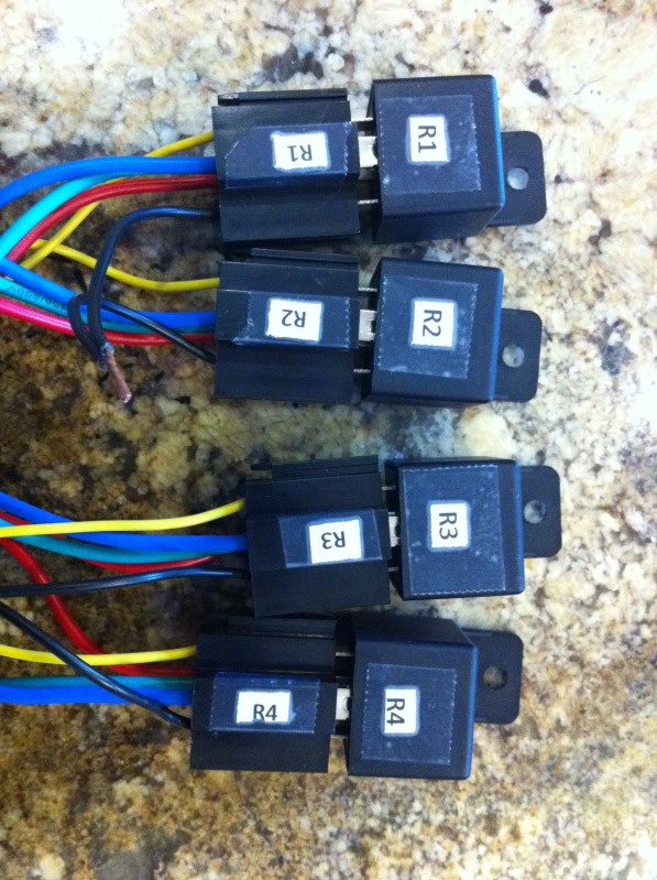
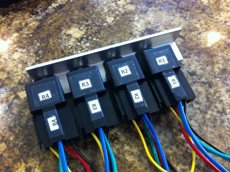
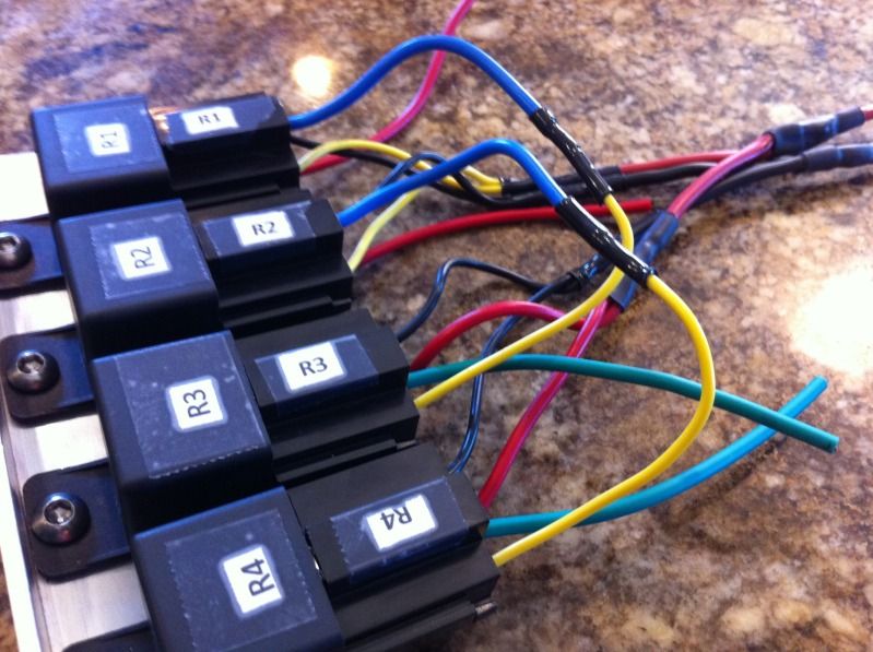
The first thing I did was prepare my relays and connectors by labeling them R1, R2, R3, and R4.
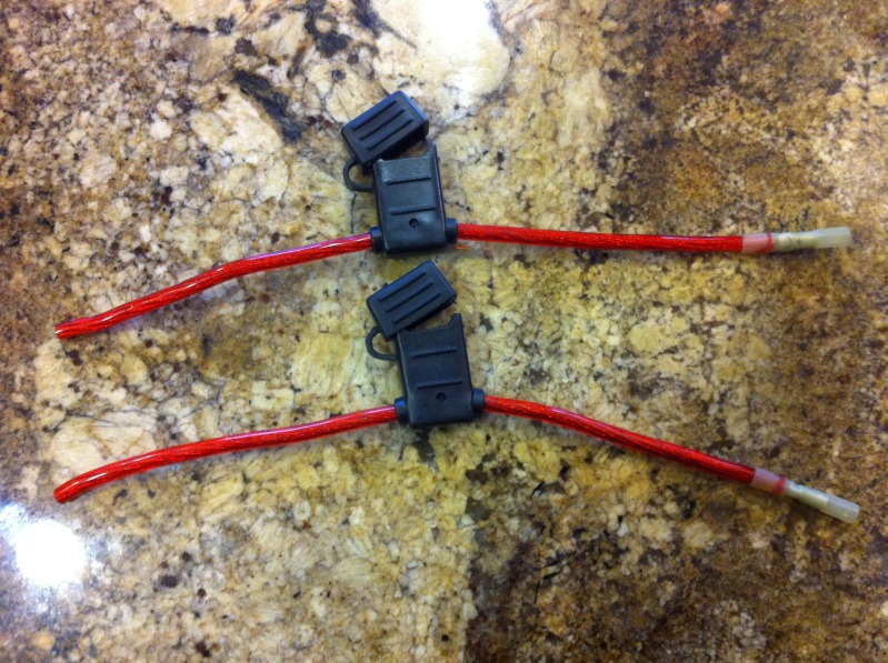
Here are the fuse holders with a butt connector crimped on the end and crimped on a length of 10 gauge wire long enough to reach from the battery to the relay mounting location in the trunk.
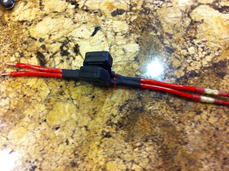
Next I put some heat shrink around them to keep the installation clean.
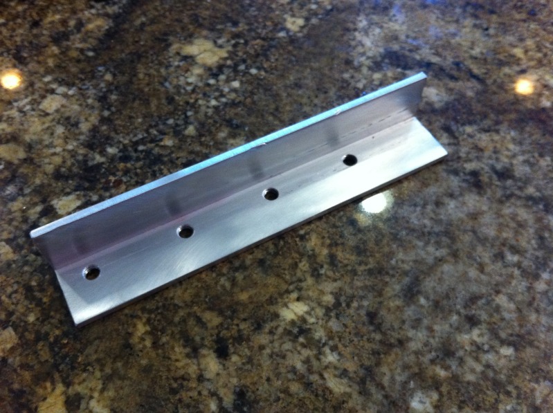
Fabricate a bracket out of 1"X1" aluminum to mount the relays on. I drilled and tapped 4 holes in it with 1-3/8" spacing to mount the relays using M6X1.0 but
The first thing I did was prepare my relays and connectors by labeling them R1, R2, R3, and R4.
Here are the fuse holders with a butt connector crimped on the end and crimped on a length of 10 gauge wire long enough to reach from the battery to the relay mounting location in the trunk.
Next I put some heat shrink around them to keep the installation clean.
Fabricate a bracket out of 1"X1" aluminum to mount the relays on. I drilled and tapped 4 holes in it with 1-3/8" spacing to mount the relays using M6X1.0 but
Thread Starter
Joined: Aug 2002
Posts: 610
Likes: 6
From: Erie, Colorado
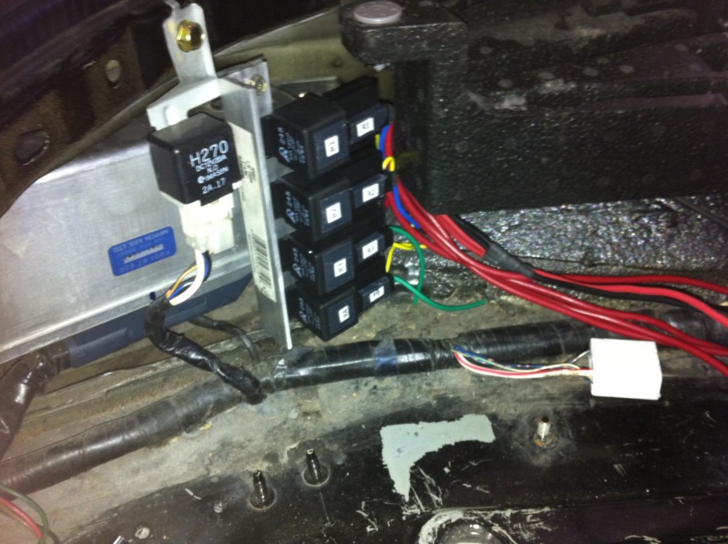
Next, I mounted the relays to the bracket.
Begin the wiring by soldering the black wires from R1 & R2 together and attaching a lead of 12 gauge wire coming off of them. These black wires should be terminal 85 on each of the relays. Then, repeat the process with R3 & R4 in the same manner, and then solder the two 12 gauge wires together with another lead of 12 gauge wire coming off of them. Regardless of where you order your parts from, ALWAYS double check that the wire colors you are using are coming from the proper terminal on the relay.
Next, repeat the same process as above using the Yellow wires (terminal 86) from R1 & R2, and the Red wires from R3 & R4 using red 12 gauge wire.
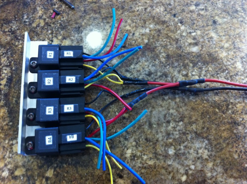
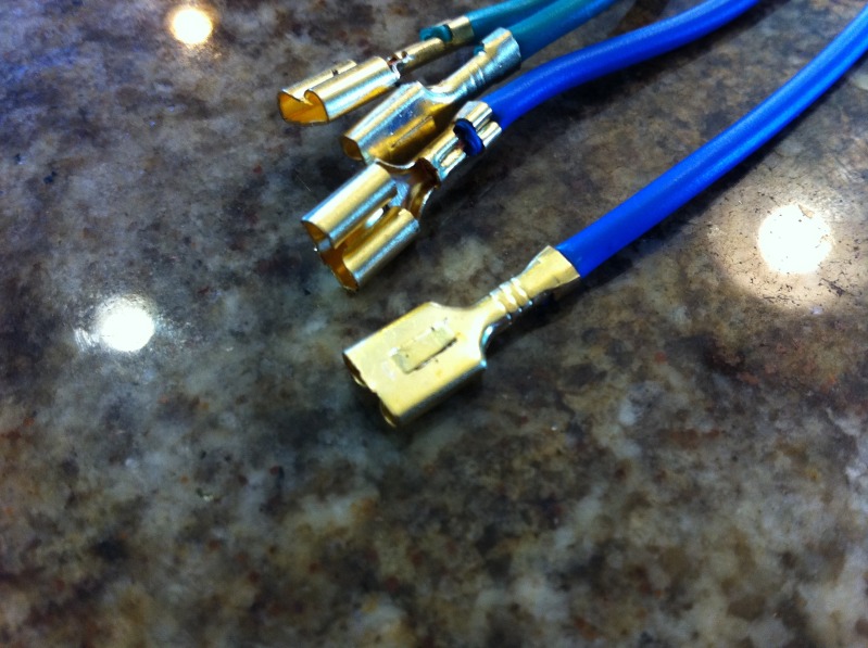
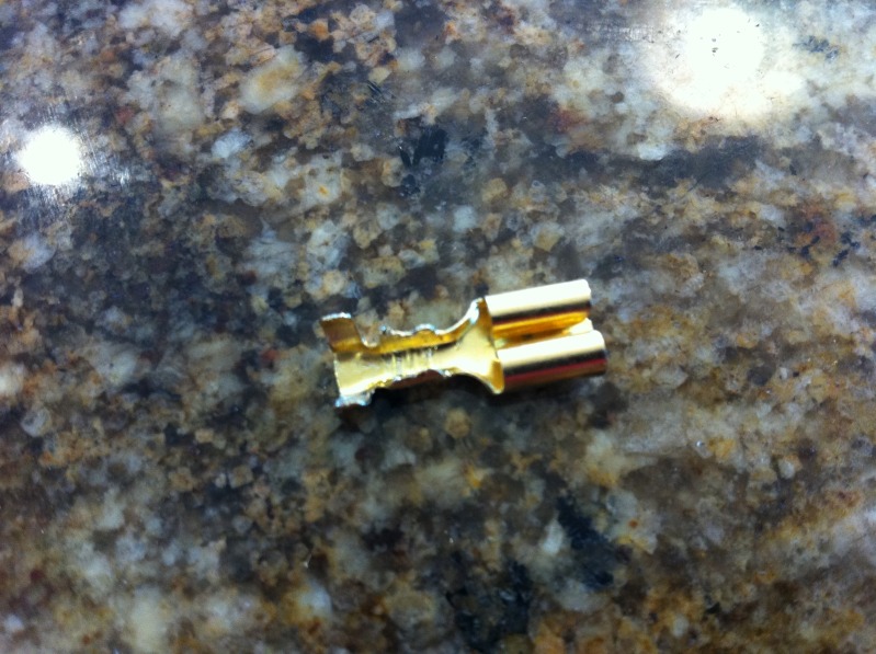
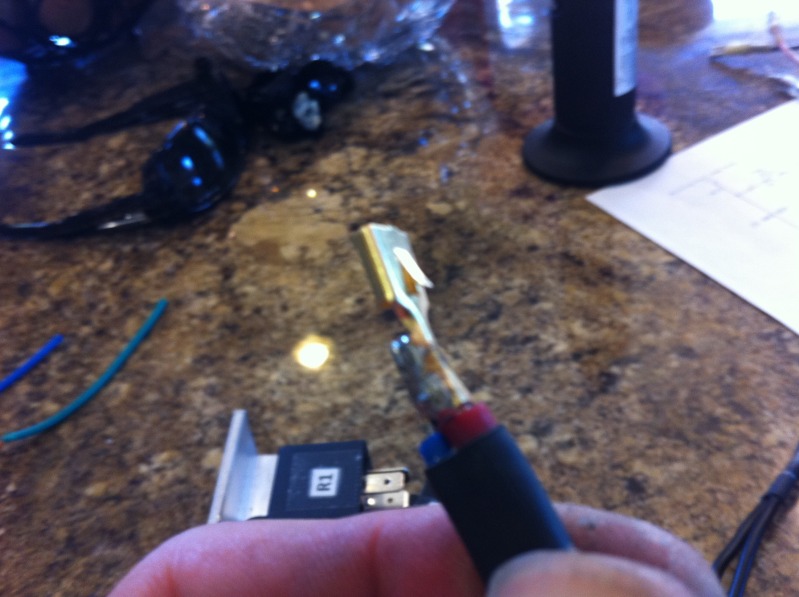
Using a small pic, or a jeweler's screwdriver, remove the Green wires (terminal 87a) from R1 & R2, and the Blue wires (terminal 87) from R3 & R4 by depressing the small tab inside of the connector on each one.
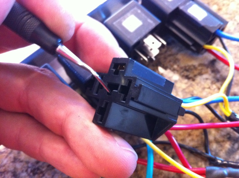
Here's a pic that shows the tab you're looking for.
Begin the wiring by soldering the black wires from R1 & R2 together and attaching a lead of 12 gauge wire coming off of them. These black wires should be terminal 85 on each of the relays. Then, repeat the process with R3 & R4 in the same manner, and then solder the two 12 gauge wires together with another lead of 12 gauge wire coming off of them. Regardless of where you order your parts from, ALWAYS double check that the wire colors you are using are coming from the proper terminal on the relay.
Next, repeat the same process as above using the Yellow wires (terminal 86) from R1 & R2, and the Red wires from R3 & R4 using red 12 gauge wire.
Using a small pic, or a jeweler's screwdriver, remove the Green wires (terminal 87a) from R1 & R2, and the Blue wires (terminal 87) from R3 & R4 by depressing the small tab inside of the connector on each one.
Here's a pic that shows the tab you're looking for.
Thread Starter
Joined: Aug 2002
Posts: 610
Likes: 6
From: Erie, Colorado
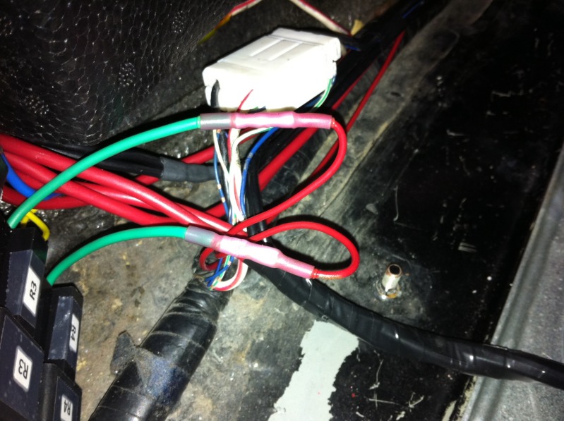
Next, join the Blue wire (terminal 87) from R1 to the Yellow wire (terminal 86) on R3. Then repeat the process for R2 & R4.
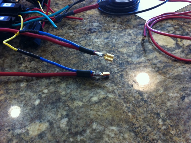
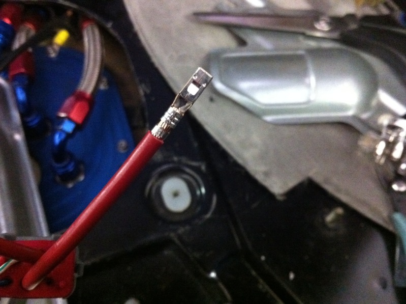
Using the 2 of the wires you removed from the connector earlier, pry open the crimps and remove the wire taking care not to damage the connector. I'm not sure why they provided such inadequate wire in these connectors for 40 Amp relays, but we will change it out anyway.
Remove the blue wires (terminal 87) from the R1 & R2 connectors that we just joined and cut ONLY the very end off. Carefully crimp a new piece of red 10 gauge wire into the connector that you just pried open and solder it in. Make sure that the red 10 gauge wire is long enough to reach the bulkhead connector for your pumps. After it is crimped, solder it in place, and re-solder the blue wire to the SIDE of the connector, not the top like I did as this makes it difficult to fit back into the plug.
Thread Starter
Joined: Aug 2002
Posts: 610
Likes: 6
From: Erie, Colorado
Make sure you push the tab back out on the connectors before reinserting them into the appropriate plugs. Remember, the one attached to R3 goes back into R1 (terminal 87), and R4 goes back into R2 (terminal 87).
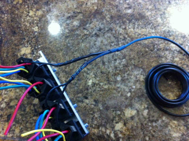
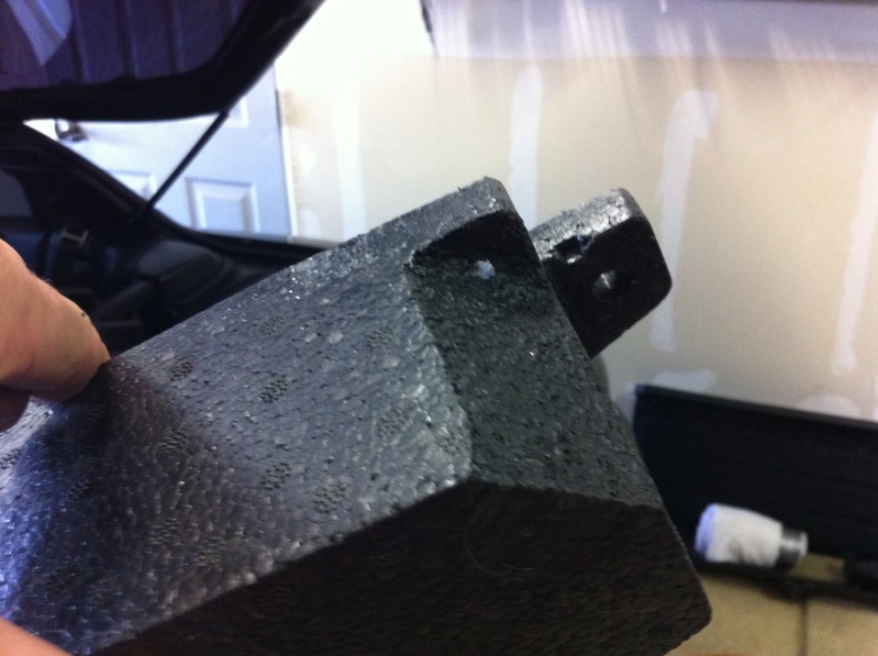
If you are going to mount your relays in the same place that I did, you will need to trim the corner off of the Styrofoam holder that holds your spare tire tools to make room for the wires coming out of the plugs.
Use a self tapping sheet metal screw to mount the bracket on the extra tab next to the existing relay inside the drivers side of the trunk.
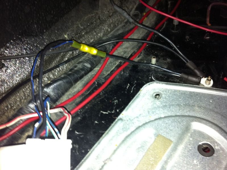
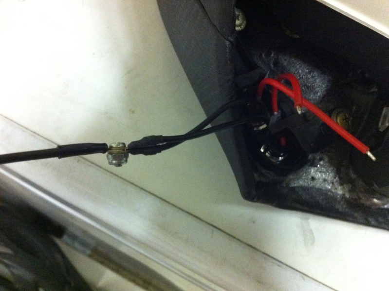
Using the stud in the trunk that is just in front of the fuel pump access cover, crimp a ring terminal on the black 12 gauge wire that comes from the relays (terminal 85), and an additional wire that runs directly to the battery negative terminal.
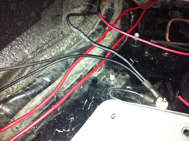
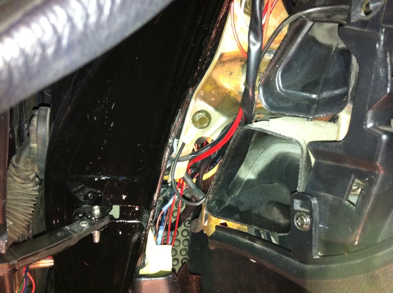
Next, join the small black w/ blue wire to the larger black wire coming out of the factory fuel pump wire harness and run it to the same stud using another ring terminal. You should also crimp another ring terminal on an additional black 12 gauge wire that gets grounded DIRECTLY to the screws on the top of the fuel pump assembly that holds it into the tank. You can't see all of it in this picture, but you can see it later on.
If you are going to mount your relays in the same place that I did, you will need to trim the corner off of the Styrofoam holder that holds your spare tire tools to make room for the wires coming out of the plugs.
Use a self tapping sheet metal screw to mount the bracket on the extra tab next to the existing relay inside the drivers side of the trunk.
Using the stud in the trunk that is just in front of the fuel pump access cover, crimp a ring terminal on the black 12 gauge wire that comes from the relays (terminal 85), and an additional wire that runs directly to the battery negative terminal.
Next, join the small black w/ blue wire to the larger black wire coming out of the factory fuel pump wire harness and run it to the same stud using another ring terminal. You should also crimp another ring terminal on an additional black 12 gauge wire that gets grounded DIRECTLY to the screws on the top of the fuel pump assembly that holds it into the tank. You can't see all of it in this picture, but you can see it later on.
Thread Starter
Joined: Aug 2002
Posts: 610
Likes: 6
From: Erie, Colorado
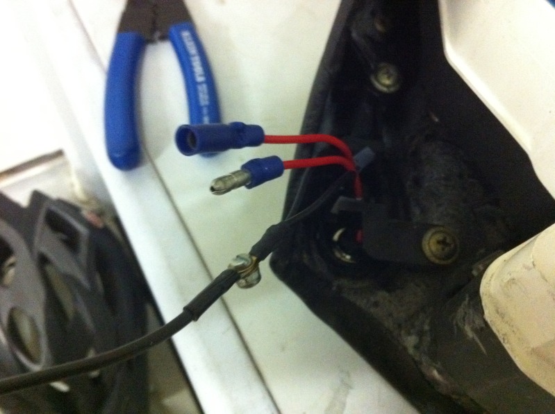
Crimp 2 more 12 gauge wires into an additional ring terminal and ensure that they are long enough to reach the plug for your fuel pumps. These will be individual grounds for each fuel pump.
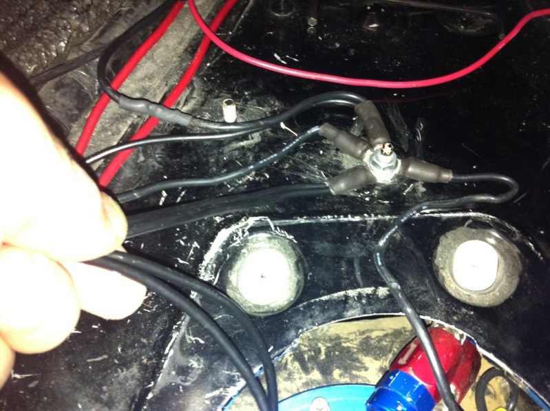
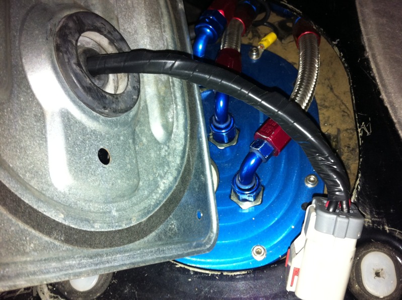
Crimp and solder the plug end onto each 10 gauge red wire for your bulkhead connector on the pumps. This is the wire that we installed earlier that comes from R1 and R2 (terminal 87) and provides the power to each pump. If you have a different pump set up, you will have to improvise on this part and adapt it to your set up. Also, do the same for the two 12 gauge black wires that we just installed for the ground on each pump.
Once they are inserted into the appropriate holes on the bulkhead connector for each pump (make sure you put the red 10 gauge wire from R1 (terminal 87) to pump 1 and the one from R2 to pump 2, tape up the wires and make sure they are adequately protected.
Next, run two red 20 gauge wires to the location in your dash where you are going to install your indicator lights. Connect one of these wires to the green wire (terminal 87a) of R3, and the other to the green wire (terminal 87a) of R4 as shown below. I forgot to take a picture, but you also need to connect the red 12 gauge wire that is tied to the R1 & R2 yellow wires (terminals 86) and the red wires of R3 & R4 (terminals 30) to the White w/Red coming from the factory fuel pump harness. This is the switched power that tells the pumps if they should turn on or not.
Thread Starter
Joined: Aug 2002
Posts: 610
Likes: 6
From: Erie, Colorado
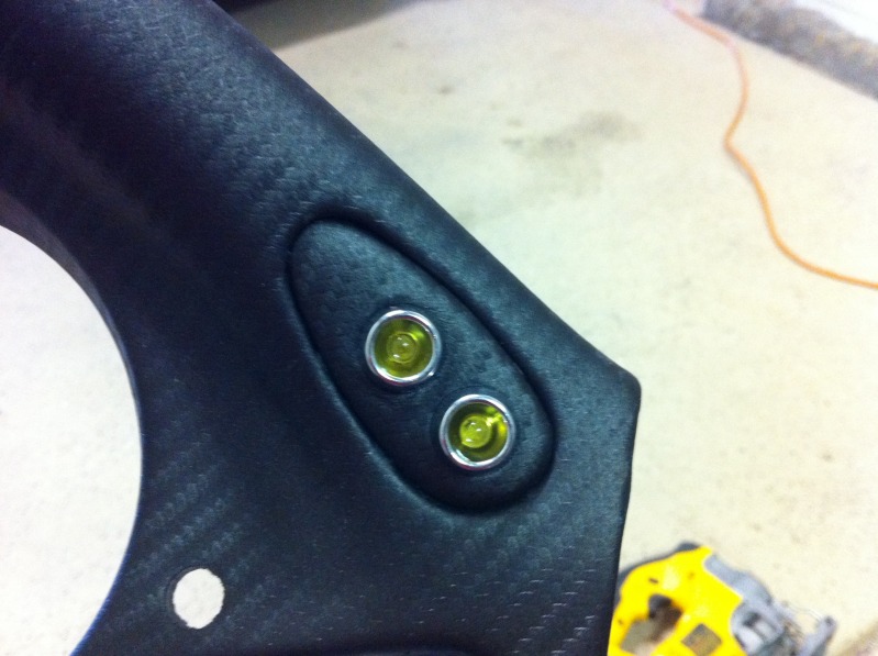
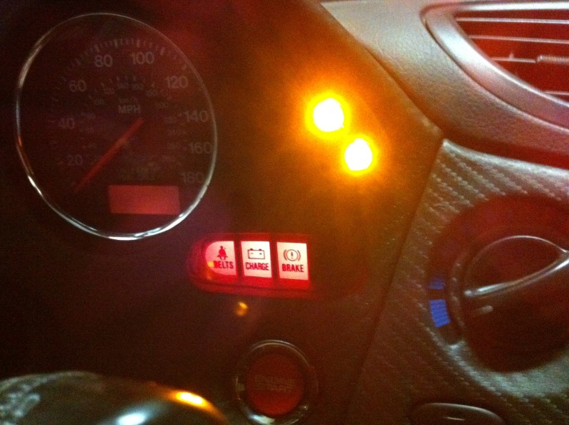
Here's an example of where I installed my indicator lights since I do not have cruise control, I felt it was the perfect location.
Since the indicator lights I purchased had ring terminals on the ground already, I crimped another ring terminal on the end of a piece of black 20 gauge and then secured them all together with a small screw and lock nut.
Use an ohm meter and determine which of the red 20 gauge wires is coming from R3, this is your indicator for pump 1 failure. Make a note of it and install the opposite connector on the other wire to prevent you from accidentally connecting pump 1 indicator wire to the pump 2 indicator wire accidentally (and vice-verse).
Next, crimp another ring terminal to the other end of the ground wire coming from the indicator lights and find a good grounding location for it. Make sure to check it with a meter to the negative terminal on the battery to ensure that it is a good ground. I used the bolt that is in the dash just to the left, and below of the gauges shown here.
At this point, assuming that you disconnected your negative battery terminal (like you should always do before working on your car) you should be able to reconnect your negative battery terminal. With the fuses removed from both of the inline fuse holders, turn the key on to the ignition position and both indicators should briefly turn on for a few seconds, then turn back off, unless you've made other modifications to your fuel pump wiring that tells the pumps to stay on all of the time. After checking that they light properly, you can use an ohm meter once again to check which fuse leads to R1 (terminal 30) and which fuse leads to R2 (terminal 30) and mark the fuses for Pump 1 and Pump 2 respectively. Insert a 30 amp fuse in pump 1 only, and check that when the key is turned on, the pump 1 indicator light goes out IMMEDIATELY when the key is turned to ignition. Then test pump 2 the same way. If it does not work as stated, you need to go back and find your error.
I hope this helps clear up some of the questions out there on rewiring the fuel pumps. The relay, wire, and fuse sizing I used may be overkill for some applications and should adjusted accordingly for YOUR application. Always remember, the fuse size is determined based on the wire size, NOT the device it is powering, however the fuse and wire size in combination should be chosen based on the maximum acceptable current draw of the device being powered.
USE THIS TUTORIAL AT YOUR OWN RISK!
I WILL NOT BE HELD RESPONSIBLE FOR ANY MISTAKES, TYPOS, OR EXAMPLES IN THIS TUTORIAL THAT MAY LEAD YOU TO MAKE A MISTAKE THAT COULD DAMAGE, OR DESTROY YOUR CAR OR YOURSELF!
IF YOU ARE NOT 100% CONFIDENT IN WHAT YOU ARE DOING, DON'T DO IT!!!
Trending Topics


Thread Starter
Joined: Aug 2002
Posts: 610
Likes: 6
From: Erie, Colorado
Here are a few more schematics for your reference. These show how I would approach a few different configurations using a low fuel pressure switch (or two) which I am thinking about adding.
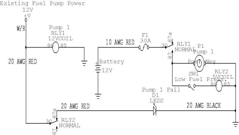
This is using a single low fuel pressure switch to turn on both lights to let you know there is a major problem with the fuel supply. Please excuse the improper representation of the low pressure switch. I do not have the proper software installed on this PC, it is only meant for PCB design. Also note that the low pressure switches used in these examples would be NO/HC (Normally Open/Held Closed) pressure switches.

This example is using two separate low pressure switches to turn on each light individually to indicate low pressure on a specific pump. If you decide to go this route, each low pressure switch would have to be installed on the pump outlets with a check valve after each one, before the two pumps tie into the main fuel line. Ultimately, you would probably want to use a separate LED indicator for low pressure so that low pressure can't be confused with a loss of power to the pump.

This one is for a single fuel pump with a low fuel pressure switch and a single pump fail indicator.
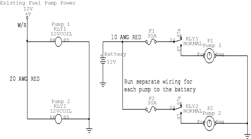
And... Plain old dual fuel pump wiring without any pump fail indication.
This is using a single low fuel pressure switch to turn on both lights to let you know there is a major problem with the fuel supply. Please excuse the improper representation of the low pressure switch. I do not have the proper software installed on this PC, it is only meant for PCB design. Also note that the low pressure switches used in these examples would be NO/HC (Normally Open/Held Closed) pressure switches.
This example is using two separate low pressure switches to turn on each light individually to indicate low pressure on a specific pump. If you decide to go this route, each low pressure switch would have to be installed on the pump outlets with a check valve after each one, before the two pumps tie into the main fuel line. Ultimately, you would probably want to use a separate LED indicator for low pressure so that low pressure can't be confused with a loss of power to the pump.
This one is for a single fuel pump with a low fuel pressure switch and a single pump fail indicator.
And... Plain old dual fuel pump wiring without any pump fail indication.

Thread Starter
Joined: Aug 2002
Posts: 610
Likes: 6
From: Erie, Colorado
It is absolutely not useless to have the lights without the pressure switches. If you lose a pump when there are two in the system, you may not realize it immediately and could potentially be running on one pump for a long time. This defeats the purpose of having redundant fuel pumps. Not to mention the fact that if you have enough HP to require two pumps, your car may run fine on only one until you make a hard pull and find out that you didn't have enough fuel supply for your setup anymore. Can you say rebuild? I agree that the pressure switches add a lot more security, that is why I've been considering them. However, it is quite a bit more of an investment to add them in. The check valves alone are $70 a piece when I did a quick search for them the other day.
Thread Starter
Joined: Aug 2002
Posts: 610
Likes: 6
From: Erie, Colorado
@ nismosilvia270r - your absolutely right in saying that power to the pump does not mean that the pump is working, and I never said that it did, however NO power to the pump DEFINITELY means that it is not working. I never said this was a fool-proof solution, but I did provide a schematic to integrate the low pressure switch which would make it a much more reliable option for knowing that the fuel supply is ok. However, it still isn't fool-proof unless you add flow monitoring as well. I am perfectly aware of the limitations of an indicator light only showing whether there is power to the pump or not. This was a solution for a recent issue where one of my new pumps had began blowing fuses, but because I had multiple pumps, I still had fuel pressure.

@ nismosilvia270r - your absolutely right in saying that power to the pump does not mean that the pump is working, and I never said that it did, however NO power to the pump DEFINITELY means that it is not working. I never said this was a fool-proof solution, but I did provide a schematic to integrate the low pressure switch which would make it a much more reliable option for knowing that the fuel supply is ok. However, it still isn't fool-proof unless you add flow monitoring as well. I am perfectly aware of the limitations of an indicator light only showing whether there is power to the pump or not. This was a solution for a recent issue where one of my new pumps had began blowing fuses, but because I had multiple pumps, I still had fuel pressure.
(you obviously know what you know, just trying to share your behind-the-scenes thought processes)
The original schematic isn't quite what you need. It will only illuminate the light if the fuse blows, but not if the pump fails, or gets unplugged, or has a bad ground, or any other situation that doesn't pop the fuse.

Thread Starter
Joined: Aug 2002
Posts: 610
Likes: 6
From: Erie, Colorado
I agree completely. That's why I recommend installing check valves with a low pressure switch inline between the pump and the check valve on each pump.

