Headlights Retractor Wiring - Quick Help..!-
#1
Senior Member
Thread Starter
iTrader: (3)
Join Date: May 2010
Location: Santiago, Chile
Posts: 373
Likes: 0
Received 0 Likes
on
0 Posts
Guys,
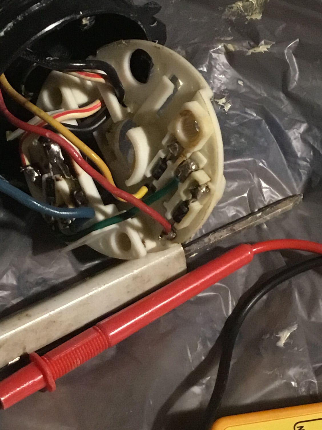
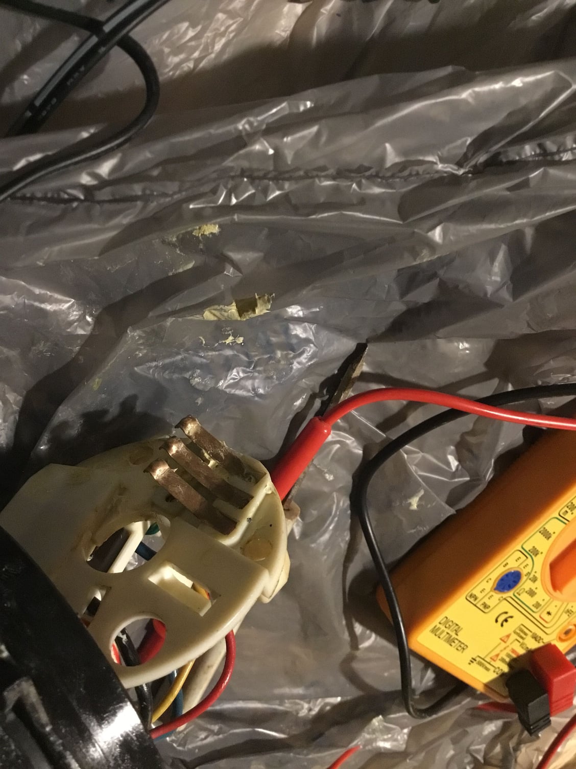
I need some quick help (for those who know) about the headlights retractor motor wiring.
Am in the process of rewiring the lights on a full purpose Race Car FD, because of the Time Attack rules the car needs to have all their stock lights in working condition. So as I took everything out for painting I decided to rewire the lights in his own independent circuit.
Anyway, last night I fried both retractor motors trying to find out how to wire them through a Relay & Switch , they are being rebuilt now and I would like to get some advice before I toast them again.
My car a 94 JDM FD

subir fotos

subir imagen
The Retra 4 Wires

subir fotos gratis
I tried to understand this, but it didn´t work last night...

subirimagenes
Am not an electrician at all, so I would like to make it as simple as possible.
On the JDM Harness :
FAT BLACK WIRE Ground
FAT RED/ WHITE WIRE Constant Fused 12V ??
SLIM YELLOW WIRE 87A on Relay ???
SLIM RED WIRE 87 Accessory on Relay ???
I have a toggle switch SPST 30AMP and a 5 pin Relay ready for the wiring...
Any help is appreciated, as from this side of the world FD´s are unicorns...
Gracias..!!
I need some quick help (for those who know) about the headlights retractor motor wiring.
Am in the process of rewiring the lights on a full purpose Race Car FD, because of the Time Attack rules the car needs to have all their stock lights in working condition. So as I took everything out for painting I decided to rewire the lights in his own independent circuit.
Anyway, last night I fried both retractor motors trying to find out how to wire them through a Relay & Switch
My car a 94 JDM FD

subir fotos

subir imagen
The Retra 4 Wires

subir fotos gratis
I tried to understand this, but it didn´t work last night...

subirimagenes
Am not an electrician at all, so I would like to make it as simple as possible.
On the JDM Harness :
FAT BLACK WIRE Ground
FAT RED/ WHITE WIRE Constant Fused 12V ??
SLIM YELLOW WIRE 87A on Relay ???
SLIM RED WIRE 87 Accessory on Relay ???
I have a toggle switch SPST 30AMP and a 5 pin Relay ready for the wiring...
Any help is appreciated, as from this side of the world FD´s are unicorns...
Gracias..!!
#4
on usdm & cdn cars they used a simple 4 or 5 plug relay, on my jdm grey import the retra relay is entirely different, and instead of being in the front near the hood release, it's t ight beside the drivers right shin (rhd remember)
most people leave the factory wording in place as they don't wamt to mess with it
the wiring diagram you Have posted looks to be the USDM wiring...
I would do a search on the headlight motirs on the forum as I know a few different members Have taken them apart to better understand how they work, and tri to write something from that...
https://www.rx7club.com/showthread.php?t=1050851
read post 6 might help you out a bit...
J.
#5
Senior Member
Thread Starter
iTrader: (3)
Join Date: May 2010
Location: Santiago, Chile
Posts: 373
Likes: 0
Received 0 Likes
on
0 Posts
J.
Thanks a lot for the feedback... I actually found something based on your post that seems to help...

subir imagenes gratis
According to the FSM there is:
One Constant 12V, probably one of the "fat" wires
One Constant Ground, probably the other "fat" wire.
And I should give 12V to one wire for Close, and 12V to the other for Open.
So basically I should have 2 Wires on 12V at the same time for Open, or 2 Wires on 12V at the same time for closing... And a constant Ground...
Am pretty sure that´s what I did before and I toasted both motors ..!!
Thanks a lot for the feedback... I actually found something based on your post that seems to help...

subir imagenes gratis
According to the FSM there is:
One Constant 12V, probably one of the "fat" wires
One Constant Ground, probably the other "fat" wire.
And I should give 12V to one wire for Close, and 12V to the other for Open.
So basically I should have 2 Wires on 12V at the same time for Open, or 2 Wires on 12V at the same time for closing... And a constant Ground...
Am pretty sure that´s what I did before and I toasted both motors ..!!
#6
We're lucky the Mazda diagrams are easy to read. The VW ones I fool with are not so easy.
Here's how I'd wire it up:
FAT BLACK WIRE -> GROUND
FAT RED/WHITE -> 12V+ CONSTANT
THIN WIRES to a new relay TERMINAL 87 AND 87A
ON RELAY:
TERMINAL 86 -> GROUND
TERMINAL 85 -> INTERIOR SWITCH PROVIDING 12V+
An option would be to tie the 12v from the headlight to terminal 85 with a diode so the lights will go up with the headlights on.
Then all you have to do is flip the smal wires tothe correct orientation to make them go UP with the switch ON.
Vince
#7
New to the Club!
Join Date: Jun 2022
Location: Tampa Bay
Posts: 1
Likes: 0
Received 0 Likes
on
0 Posts
We're lucky the Mazda diagrams are easy to read. The VW ones I fool with are not so easy.
Here's how I'd wire it up:
FAT BLACK WIRE -> GROUND
FAT RED/WHITE -> 12V+ CONSTANT
THIN WIRES to a new relay TERMINAL 87 AND 87A
ON RELAY:
TERMINAL 86 -> GROUND
TERMINAL 85 -> INTERIOR SWITCH PROVIDING 12V+
An option would be to tie the 12v from the headlight to terminal 85 with a diode so the lights will go up with the headlights on.
Then all you have to do is flip the smal wires tothe correct orientation to make them go UP with the switch ON.
Vince
Here's how I'd wire it up:
FAT BLACK WIRE -> GROUND
FAT RED/WHITE -> 12V+ CONSTANT
THIN WIRES to a new relay TERMINAL 87 AND 87A
ON RELAY:
TERMINAL 86 -> GROUND
TERMINAL 85 -> INTERIOR SWITCH PROVIDING 12V+
An option would be to tie the 12v from the headlight to terminal 85 with a diode so the lights will go up with the headlights on.
Then all you have to do is flip the smal wires tothe correct orientation to make them go UP with the switch ON.
Vince


…
Thread
Thread Starter
Forum
Replies
Last Post
Jeff20B
1st Generation Specific (1979-1985)
73
09-16-18 07:16 PM
t-von
3rd Generation Specific (1993-2002)
9
09-10-15 01:56 PM


