
Even Cheaper Bastard Cold Air Intake


RX7 lover
Joined: Jun 2005
Posts: 1,160
Likes: 3
From: UK
Ok so i just took some pictures. The quality of workmanship is not great but im in a rush for an event and i always say function over form... (because im lazy :P)
here she is

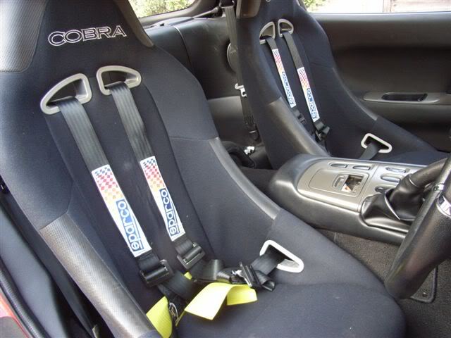
and my new seats, for good measure...
Heres a picture of how the cars laid out, the intercooler is quite large so you may have more space to play with:
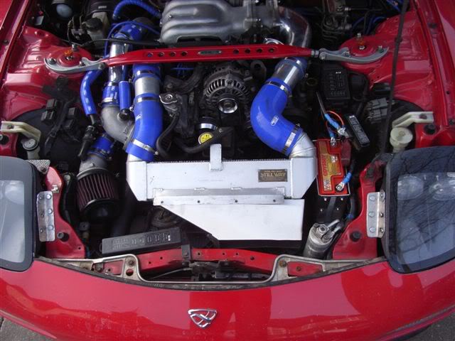
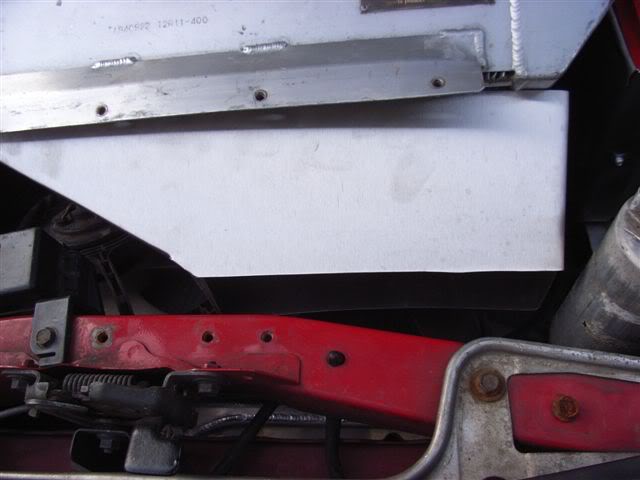
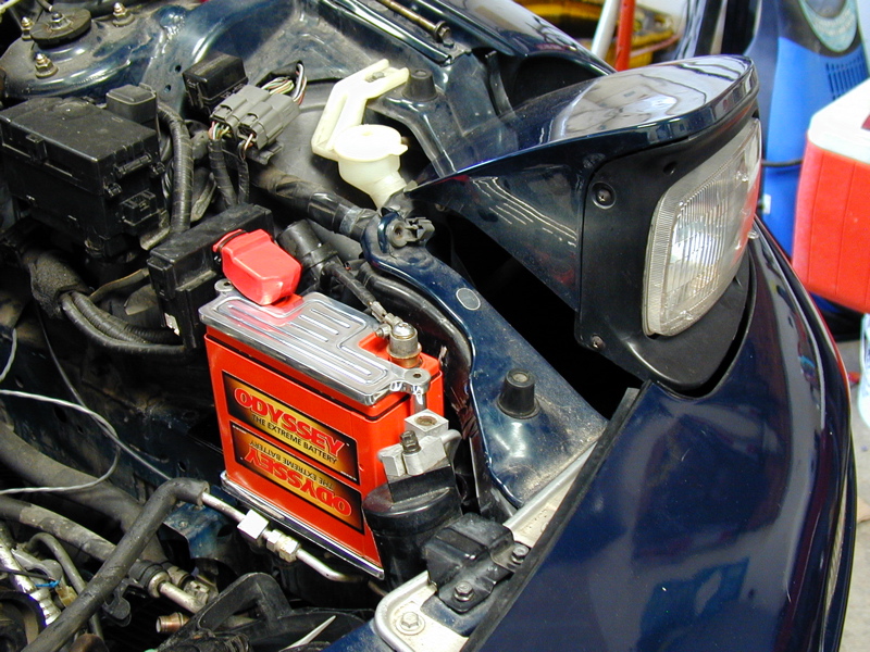
the panel infront of the intercooler i fabricated, more on that later - its the duct. i also fabricated to battery box on the right for a PC680 odysee battery. Ive done a lot of searching on this battery and have seen some bad stories, but ive had no problems so far. Never fails to start the car, however i do drive it probably every 2-3 days and the battery has only seen 2 months of use. Heres some more detailed pictures:
The box was made of a net that i drew up out of cardboard, i basically folded carboard around the battery, made sure it fitted nice and then cut out the metal and did the same.
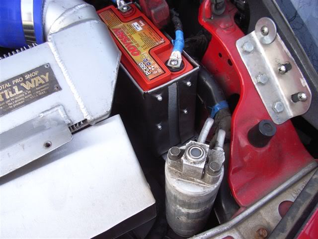
I riveted out from the inside to hold the whole thing together, the top layer under the rivit is an extension of the long side panel. I have pictures of the carboard net i made if you want to see them.
This box is then riveted to a single piece of sheet that i cut to fit into the existing two bolt holes on the chassis rail for the original battery box base. This piece was then riveted to the bottom of the battery box itself.
The top right of the box is cable tied to a solid point on the inner wing to stop the bottom sheet flexing with cornering.
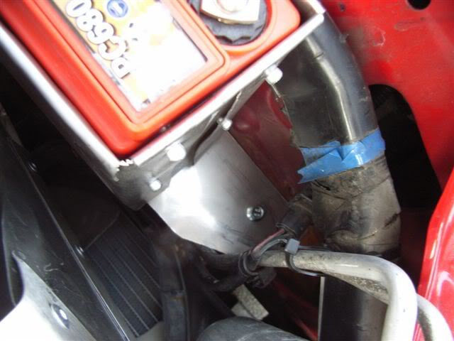
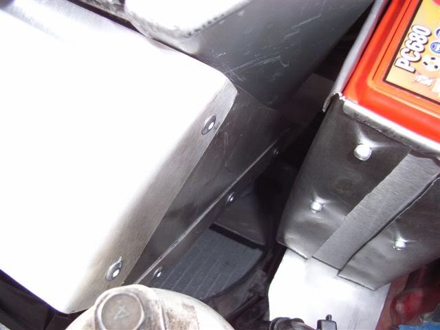
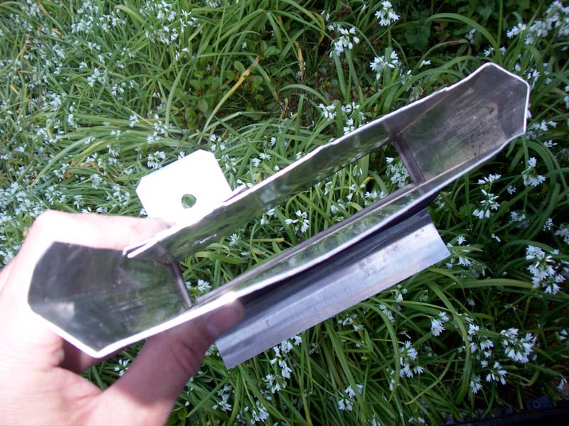
as for the intercooling ducting, the AC bottle thingy got in the way of my duct. The lines are pretty stiff and supportive so ive removed the bracket from it and cable tied the lines to some of the loom of the car. The ic duct is comprised of 4 bits of sheet shaped to be conical. I had to do a bit of funky bending to get this lot in, and its not perfect, but it needs more tweaking im not finished yet.
Intake elbow side of engine:
exhaust port side of engine:
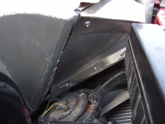
i have no photos of the bottom piece, but its a large piece i have bolted to the crossbar just above the steering rack. There will be plenty of spare holes there if you have removed the stock airbox and IC. The whole lot is riveted together:
The front will then follow the path of the stock IC duct out the nose of the car, although i am going to expose a large portinon of the duct through the bumper )possibly 1/3 of whole hole in front bumper)
this part isnt done yet, but the plan is to build it to be removeable, i plan to do this by shaping the end of the duct so that it slides over the end of what ive got above, im then doing to weld some captive nuts to the inside of the existing duct so i can drill the new piece in the right place and insert a bolt through into the captive nut to hold it.
More pics of this when im further along with it, car has to be done by april 19th sooo...
here she is
and my new seats, for good measure...
Heres a picture of how the cars laid out, the intercooler is quite large so you may have more space to play with:
the panel infront of the intercooler i fabricated, more on that later - its the duct. i also fabricated to battery box on the right for a PC680 odysee battery. Ive done a lot of searching on this battery and have seen some bad stories, but ive had no problems so far. Never fails to start the car, however i do drive it probably every 2-3 days and the battery has only seen 2 months of use. Heres some more detailed pictures:
The box was made of a net that i drew up out of cardboard, i basically folded carboard around the battery, made sure it fitted nice and then cut out the metal and did the same.
I riveted out from the inside to hold the whole thing together, the top layer under the rivit is an extension of the long side panel. I have pictures of the carboard net i made if you want to see them.
This box is then riveted to a single piece of sheet that i cut to fit into the existing two bolt holes on the chassis rail for the original battery box base. This piece was then riveted to the bottom of the battery box itself.
The top right of the box is cable tied to a solid point on the inner wing to stop the bottom sheet flexing with cornering.
as for the intercooling ducting, the AC bottle thingy got in the way of my duct. The lines are pretty stiff and supportive so ive removed the bracket from it and cable tied the lines to some of the loom of the car. The ic duct is comprised of 4 bits of sheet shaped to be conical. I had to do a bit of funky bending to get this lot in, and its not perfect, but it needs more tweaking im not finished yet.
Intake elbow side of engine:
exhaust port side of engine:
i have no photos of the bottom piece, but its a large piece i have bolted to the crossbar just above the steering rack. There will be plenty of spare holes there if you have removed the stock airbox and IC. The whole lot is riveted together:
The front will then follow the path of the stock IC duct out the nose of the car, although i am going to expose a large portinon of the duct through the bumper )possibly 1/3 of whole hole in front bumper)
this part isnt done yet, but the plan is to build it to be removeable, i plan to do this by shaping the end of the duct so that it slides over the end of what ive got above, im then doing to weld some captive nuts to the inside of the existing duct so i can drill the new piece in the right place and insert a bolt through into the captive nut to hold it.
More pics of this when im further along with it, car has to be done by april 19th sooo...
Thread Starter
Magnet Boy
Joined: Jan 2007
Posts: 251
Likes: 1
From: NorCal
Cool Bob, thanks for sharing that!!
I have a Greddy SMIC and I plan to do something similar to your IC duct. I kind of wanted to pull out the stock duct altogether, but it is nice the way it catches the incoming air in front. I think I am going to start with that part and work backwards to the IC itself.
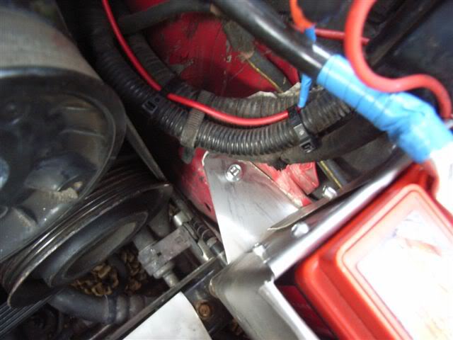
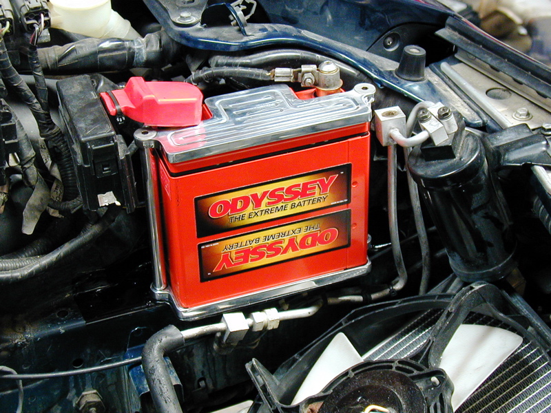
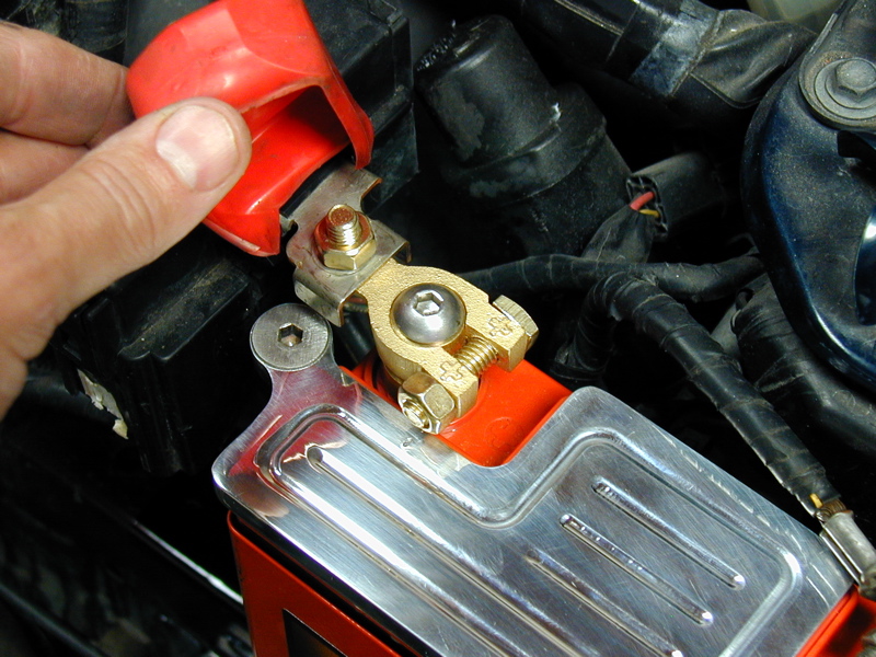
I also have an Odyssey battery. I bought their "billet aluminum mount" and had a small plate welded to the chassis to hold it down. Here's some shots:
I have a Greddy SMIC and I plan to do something similar to your IC duct. I kind of wanted to pull out the stock duct altogether, but it is nice the way it catches the incoming air in front. I think I am going to start with that part and work backwards to the IC itself.
I also have an Odyssey battery. I bought their "billet aluminum mount" and had a small plate welded to the chassis to hold it down. Here's some shots:
RX7 lover
Joined: Jun 2005
Posts: 1,160
Likes: 3
From: UK
Very nice! i was looking for those style terminals for mine but could not find any.
I will not be using the stock plastic front piece of the IC, it will all be sheet stainless. I am just going to follow the lines of it.
I will not be using the stock plastic front piece of the IC, it will all be sheet stainless. I am just going to follow the lines of it.
Thread Starter
Magnet Boy
Joined: Jan 2007
Posts: 251
Likes: 1
From: NorCal
Originally Posted by BobfisH
Very nice! i was looking for those style terminals for mine but could not find any.
I will not be using the stock plastic front piece of the IC, it will all be sheet stainless. I am just going to follow the lines of it.
I will not be using the stock plastic front piece of the IC, it will all be sheet stainless. I am just going to follow the lines of it.
Not shown in my pic (hidden beneath the red rubber boot) is a brass marine terminal I bought at a local Kragen. This has a larger offset then the stock positive terminal and includes a post/wing-nut configuration that acts as a quick disconnect. This terminal allows me to install the stock fuse holder unit aft of the battery.
Edit: Uhhh, here's a pic showing the terminal (but not the wing nut!):
Last edited by rxcited2; Apr 16, 2007 at 01:06 PM.
Bob I think some weather stripping would go a long way for your intercooler duct. It will stop the duct cutting up your intercooler when the engine torques and it will seal much better. As we can see the bottom of the duct has a large opening.
On a side note, I am planning to do some FRP ducting myself. Making a good mold out of metal is going to be the hardest. Also since FRP doesn't go great on corner I will have to fill the corners and round them to the best of my abilities.
It is nice to see something like this, a simple mod which improves performance nicely.
Thread Starter
Magnet Boy
Joined: Jan 2007
Posts: 251
Likes: 1
From: NorCal
Originally Posted by BobfisH
I will not be using the stock plastic front piece of the IC, it will all be sheet stainless. I am just going to follow the lines of it.
Lives on the Forum
Joined: Dec 2001
Posts: 14,716
Likes: 10
From: San Lorenzo, California
Originally Posted by BobfisH
and my new seats, for good measure...

Thread Starter
Magnet Boy
Joined: Jan 2007
Posts: 251
Likes: 1
From: NorCal
Originally Posted by rynberg
Off-topic, but the way you've ran those shoulder harnesses is extremely dangerous and should be addressed immediately.
Lives on the Forum
Joined: Dec 2001
Posts: 14,716
Likes: 10
From: San Lorenzo, California
Shoulder harnesses need to be run within 15-20 deg of horizontal in order to provide proper restraint, otherwise, they will cause severe injury. I also can't tell how they are bolted in, so can't comment on the safety of the mounting point either.
Aside from that, 4-point belts are dangerous because of "submarining". A 5-point is better, with a 6-point being ideal.
Aside from that, 4-point belts are dangerous because of "submarining". A 5-point is better, with a 6-point being ideal.
Thread Starter
Magnet Boy
Joined: Jan 2007
Posts: 251
Likes: 1
From: NorCal
Originally Posted by rxcited2
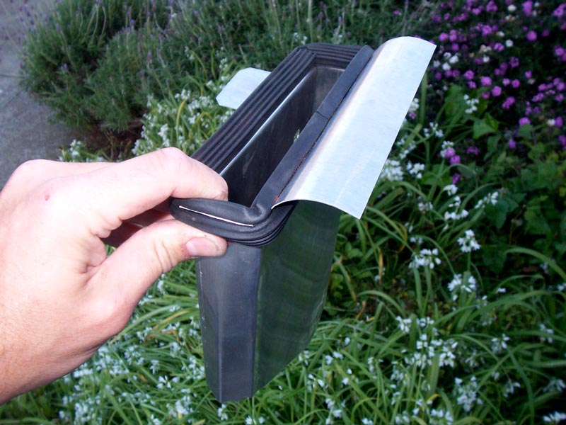
Since that original template, I have put in a Koyo racing radiator. The fitment seems to be tighter than it was originally. For now, I tweaked my existing duct to fit. Basically I squeezed it at front and aft ends so at the front it looks like < and at the back, it looks like > which makes it thin enough to slip between the radiator/fan assembly and the chassis like it did originally. I'll post a pic tonight.
RX7 lover
Joined: Jun 2005
Posts: 1,160
Likes: 3
From: UK
Originally Posted by dradon03
Bob I think some weather stripping would go a long way for your intercooler duct. It will stop the duct cutting up your intercooler when the engine torques and it will seal much better. As we can see the bottom of the duct has a large opening.
On a side note, I am planning to do some FRP ducting myself. Making a good mold out of metal is going to be the hardest. Also since FRP doesn't go great on corner I will have to fill the corners and round them to the best of my abilities.
It is nice to see something like this, a simple mod which improves performance nicely.
On a side note, I am planning to do some FRP ducting myself. Making a good mold out of metal is going to be the hardest. Also since FRP doesn't go great on corner I will have to fill the corners and round them to the best of my abilities.
It is nice to see something like this, a simple mod which improves performance nicely.
Thread Starter
Magnet Boy
Joined: Jan 2007
Posts: 251
Likes: 1
From: NorCal
My IC Duct
I finally got around to doing the duct for my IC. I used the same method as the intake duct that I started this thread about. First I mocked it up with card stock, then modeled in CAD, printed out the design, spray-glued to aluminum sheet, cut, bent and pop-riveted it together. It turned out great. For the final touch, I painted it crinkle black and made a custom bracket out of 1/8 aluminum plate.
You'll notice also that all my aluminum parts have a sparkley glow to them - they are all bead blasted and clear coated. This makes for a nice clean uniform appearance for those who are not into the polished look. Pictures of all this start here:
http://www-eng.lbl.gov/~osborn/rx-7/Page48.html
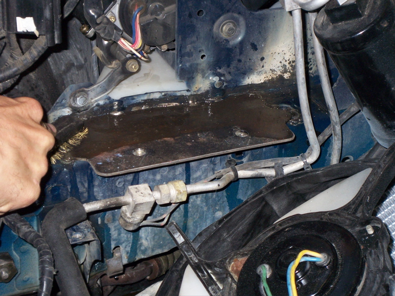
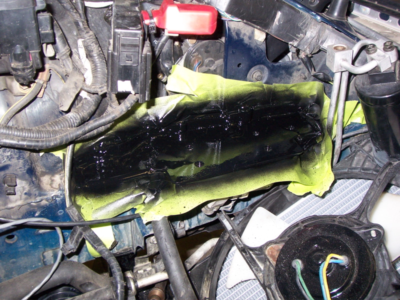
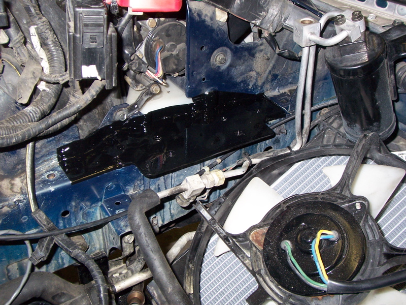
You can also see I blocked off the stock intake to the oem air box. I used high temp gasket sealant to glue a piece of aluminum sheet over the hole, then cleaned it and painted that crinkle black too. I like that crinkle black - it looks cool!
You'll notice also that all my aluminum parts have a sparkley glow to them - they are all bead blasted and clear coated. This makes for a nice clean uniform appearance for those who are not into the polished look. Pictures of all this start here:
http://www-eng.lbl.gov/~osborn/rx-7/Page48.html
You can also see I blocked off the stock intake to the oem air box. I used high temp gasket sealant to glue a piece of aluminum sheet over the hole, then cleaned it and painted that crinkle black too. I like that crinkle black - it looks cool!
Thread Starter
Magnet Boy
Joined: Jan 2007
Posts: 251
Likes: 1
From: NorCal
The whole idea with the cheaper bastard intake modification is to provide a more direct free flowing intake path of cold air to the bottom of the air box. You could just cut the box open wide on the bottom and forget the duct, but then you would be drawing hot air from the the engine bay and downstream (hot) side of the radiator in particular. Hot air intake is undesirable for performance and reliability.
A ram intake would be even better. Some guys have mounted flexible pipes which take air from the front of the car and direct it to an opening in the bottom of the air box. But space is tight. And all this would really do is allow your turbos to work less hard. They already are capable of over-boost and so the lack of ram intake is not limiting performance. If you had ram intake, it would just mean less effort by the turbos to reach maximum boost before the boost control kicks in. I don't think it would result in any significant performance gain though.


Thread Starter
Magnet Boy
Joined: Jan 2007
Posts: 251
Likes: 1
From: NorCal
http://www-eng.lbl.gov/~osborn/rx-7/.../Image546.html
Full Member
Joined: Aug 2006
Posts: 64
Likes: 0
From: Australia
Just seeing has any of you guys tried installing this shield on a Series 8?
Seems to me that the radiator mounts and some other bracket is blocking the shield from sliding down into position. Even if i did get it to slide down it looks like the undertray is in the way also.
Seems to me that the radiator mounts and some other bracket is blocking the shield from sliding down into position. Even if i did get it to slide down it looks like the undertray is in the way also.

Junior Member
Joined: May 2003
Posts: 16
Likes: 0
From: Canton, MI
Collapsed...
I built one of these and it worked pretty well, but I did have one problem. To fit it in between the radiator and chassis (maybe because of aftermarket radiator) I had to crease the ends a bit, like rxcited2 shows above. No big deal, but it may have lead to the bigger problem that it collapsed at high flows! For a while I thought I had a turbo transition problem because after the transition, the boost dropped to around 6 psi. But after pulling off the bottom tray for something else, I noticed that the sides of the duct were bowed in towards each other. I took it out to straighted it and noticed that there were actually witness marks on both sides where they had been hitting each other. So besides straightening the thing, I added a brace between the two sides. I just made a square-U out of a strip of the sheet aluminum about 1/2" wide. I put a slight V crease in the middle part to stiffen it, and riveted the two ends through the duct sides. Works like a charm now.
Other slight modifications were to extend the bottom of the duct to custom fit it around various braces, and I needed to "adjust" the mounting bolt hole closer to the duct.
Other slight modifications were to extend the bottom of the duct to custom fit it around various braces, and I needed to "adjust" the mounting bolt hole closer to the duct.
Thread Starter
Magnet Boy
Joined: Jan 2007
Posts: 251
Likes: 1
From: NorCal
Ha ha ha!
I had virtually the same thing happen to me. In my case though, my mechanic had "leaned" on the airbox. Because I had an aftermarket SMIC, I had to remove the driver's side airbox support, so leaning on it caused the even cheaper bastard to collapse just like yours!
The brace is a very good idea. In my case, I found I really didn't need to crease it; I was able to square it up and jam it back in there even though I too have an aftermarket radiator. After this I didn't have anymore problems.
Now I am onto a completely new "rich bastard" or maybe you'd call it "typical bastard with friends who are good welders" version. This is a custom set of hard-pipes for both primary and secondary turbos, and a new rigid aluminum airbox using K&N cone filters and a cold air duct like the cheap bastard, but is welded, made of thicker material (of course), and includes a "ram intake" scoop feature at the bottom. Basically the rock guard will be cut away so the cold air intake can get down below the guard, and the duct will include a scoop pointed forward to get the air.
Will try to post some pics when it is all done.
Here's a pdf of the intake duct that started the thread. This is separated onto 4 letter-size pages that can be taped together (with overlap) to allow you to print the design at home
Might save someone 20 minutes
Might save someone 20 minutes

Here's the one I meant to upload... too big to host on rx7club
http://www.multiupload.com/YE1Q3RMJMK
Thanks @rxcited2 for this.
I just did this yesterday and it works pretty good!
I have a KOYO rad and had to squeeze the duct to be thinner so I can get it in between the frame and rad.
Spool is definitely quicker with only a minimum of boost increase ... slightly less than 1 psi. I currently have dp and massive catback; still have main cat.
What I've noticed is the car doesn't loose steam up top now. Before, it would have power drop just after 6200 RPM but now it pulls till 7000 rpm. Stock airbox/duct a limitation?
While doing this, I sealed the air feed from the IC duct to the intake box so all the air goes to the IC .... so I don't know if i cleared the restriction of the intake box or better airflow to the IC that gave me better top end. (If I don't close this feed, I can see air flow between diverted from the IC)