
Engineering a better harness bar (warning: long…)

Lives on the Forum
Joined: Dec 2001
Posts: 14,716
Likes: 10
From: San Lorenzo, California
Rob, very nice to see actual engineering design applied to aftermarket parts, especially those involving safety. Everyone here should understand that the real purpose of this bar should be considered a safe mounting point for harnesses for auto-x and track days. Harnesses should not be used for street driving. Obviously, in any kind of real "race" situation, a rollbar with appropriate harness bar would be installed into the car.
-Tyler, PE

Joined: Aug 2005
Posts: 2,720
Likes: 1
From: Greenwood/Hartsville, SC.
Rob,
I first have to start off by saying, very nice work and attention to detail. There seems to be a very high potential/interest for a well engineered harness bar for FD owners.
Quick question for you:
1.) Relating to the machining operation, which would be required on the ends of the x-bar.....if you were to keep the x-sec uniform along its length wouldn’t you reduce stress concentrations were the bar steps down in x-sec? (Near the radius more specifically) This would also increase the clearance hole bearing area and eliminate a machining operation?
- By the way...the central harness attachment is a great idea. One less factor when applying Von Mises.
What you're hoping for is a best case scenario, consisting of a love tap at 3mph, squarely into a flat object. Real like doesn't work that way. What probably will happen is that, in the event of a typical street accident, the screws holding the amp in place will rip right thru the plastic, and amp and cargo divider will go their seperate ways. I don't even want to think what would happen if something happened on the track.
http://youtube.com/watch?v=srUv0PG4_RE
(if the link doesn't work, search for 'taxi driver accident', comes up as first video, you need to log in to view)
*edit* same video, but doesn't require logging in or signing up:
http://www.youtube.com/watch?v=fPgcp00jPtw
One of the last things I want is an amp with nice, sharp cooling fins floating about. Mount it to sheetmetal, seriously, for your and whomever is riding with you (I'm assuming that you care enough about them to let them ride in your FD) own good.


Sorry to the OP for the hijack (but hey, since this thread is ultimately about safety...), and sorry to you, not meaning to pick on you, but you might want to rethink that.
What you're hoping for is a best case scenario, consisting of a love tap at 3mph, squarely into a flat object. Real like doesn't work that way. What probably will happen is that, in the event of a typical street accident, the screws holding the amp in place will rip right thru the plastic, and amp and cargo divider will go their seperate ways. I don't even want to think what would happen if something happened on the track.
http://youtube.com/watch?v=srUv0PG4_RE
(if the link doesn't work, search for 'taxi driver accident', comes up as first video, you need to log in to view)
*edit* same video, but doesn't require logging in or signing up:
http://www.youtube.com/watch?v=fPgcp00jPtw
One of the last things I want is an amp with nice, sharp cooling fins floating about. Mount it to sheetmetal, seriously, for your and whomever is riding with you (I'm assuming that you care enough about them to let them ride in your FD) own good.

you know i was thinking about this design some more. for correct functioning of this bar it is required that the shoulder straps are perfectly aligned with the slot in the bar. otherwise you will encounter some twisting force and the strap or mounting hardware will be making contact with the inner corner of the slot. at best this becomes a pivot point that is no longer on the axis of the bar and at worst it is a sharp edge on soft webbing. Its basically impossible to guaranty this alignment because the seats have a wide range of adjustment and might not even be stock anymore. thoughts on this?

Thread Starter
Place your ad here...
Joined: Apr 2002
Posts: 1,336
Likes: 2
From: Dayton, OH
Rob, very nice to see actual engineering design applied to aftermarket parts, especially those involving safety. Everyone here should understand that the real purpose of this bar should be considered a safe mounting point for harnesses for auto-x and track days. Harnesses should not be used for street driving. Obviously, in any kind of real "race" situation, a rollbar with appropriate harness bar would be installed into the car.
-Tyler, PE
-Tyler, PE
Thank you for this statement!! This is what I was trying to relay earlier in this thread, but I think you said it much more clearly than I did.
(BTW, I never realize you were licensed
 )
)-Rob
Thread Starter
Place your ad here...
Joined: Apr 2002
Posts: 1,336
Likes: 2
From: Dayton, OH
Quick question for you:
1.) Relating to the machining operation, which would be required on the ends of the x-bar.....if you were to keep the x-sec uniform along its length wouldn’t you reduce stress concentrations were the bar steps down in x-sec? (Near the radius more specifically) This would also increase the clearance hole bearing area and eliminate a machining operation?
- By the way...the central harness attachment is a great idea. One less factor when applying Von Mises.
Generally speaking, you are basically correct. However, in this design the principle loading directions are in a different plane, and are largely unaffected by the smaller cross section in these areas. I've also added in radiused corners (fillets) which helps reduce stress concentrations significantly. The remaining bearing surface is still plenty large enough to support full loading.
You are correct that eliminating the change in cross-section would reduce machining cost for the bar (and therefore, would be a positive design change). However, it would force a redesign of the mounting brackets. The resulting mounting brackets would need to be larger (mainly taller). This adds significant cost to these components (probably more than I save with the bar). Plus, I'm somewhat limited on space, as I want all the components to fit under the stock plastic pieces without modification.
-Rob
Thread Starter
Place your ad here...
Joined: Apr 2002
Posts: 1,336
Likes: 2
From: Dayton, OH
Its basically impossible to guaranty this alignment because the seats have a wide range of adjustment and might not even be stock anymore. thoughts on this?
otherwise you will encounter some twisting force and the strap or mounting hardware will be making contact with the inner corner of the slot. at best this becomes a pivot point that is no longer on the axis of the bar and at worst it is a sharp edge on soft webbing.
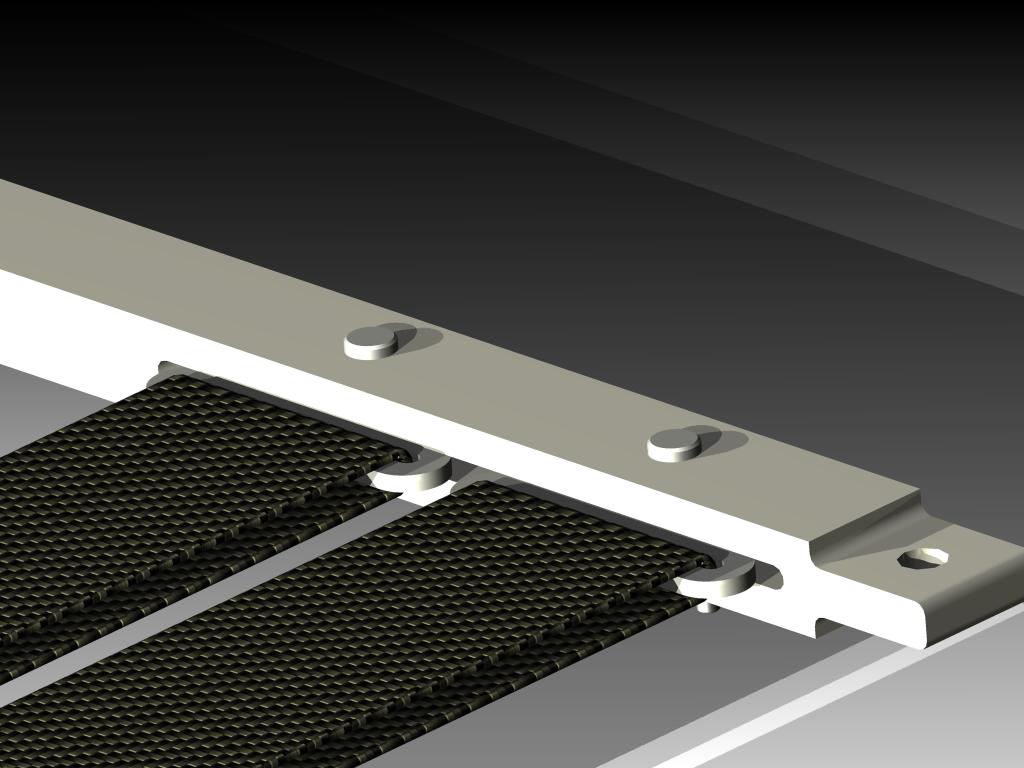
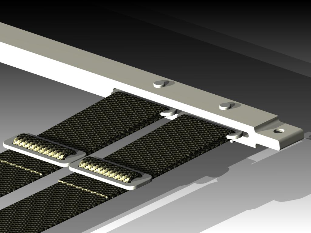
The webbing will NOT come into contact with the bar. At worst, the steel from the harness ends will contact the aluminum bar. This would only result in aesthetic wear of the aluminum, but not any type of structural failure. I think a quick picture will help to clarify this point:
This is an example of the bar with two standard harness ends installed (the third harness end standing by itself is simply for reference).

-Rob
Newb Photog
Joined: Jul 2001
Posts: 2,171
Likes: 0
From: new jersey
If this is being CNC's, why not make the harness end part of the design (one piece)? Why does it hace to come out, looks like it can be one solid piece?
Sorry if I missed the explanation some where. It just doesn't look like it can be adjusted, so a one piece solution seems feasible.
Sorry if I missed the explanation some where. It just doesn't look like it can be adjusted, so a one piece solution seems feasible.
Thread Starter
Place your ad here...
Joined: Apr 2002
Posts: 1,336
Likes: 2
From: Dayton, OH
If this is being CNC's, why not make the harness end part of the design (one piece)? Why does it hace to come out, looks like it can be one solid piece?
Sorry if I missed the explanation some where. It just doesn't look like it can be adjusted, so a one piece solution seems feasible.
Sorry if I missed the explanation some where. It just doesn't look like it can be adjusted, so a one piece solution seems feasible.
1. It would increase machining cost considerably. Since harness ends are cheap and readily available (they usually come with the harness), there's no point in the added expense. As they say, no reason to re-invent the wheel
2. In order to make an "integrated harness end" out of aluminum, it would need to be extremely beefy. This further adds to the increased expense. Using the steel harness ends provides a stronger and cheaper alternative.
3. I want to be able to quickly remove my harness when not in use. This provides me with that ability.
-Rob
PV = nRT
Joined: Jan 2003
Posts: 2,250
Likes: 0
From: New Zealand (was California)
We absolutely need more individuals like Rob. People focused and dedicated to good engineering for purposes of making a well designed, non-disposable, and appreciated product while staying NOT centered on the best way to extract the most cash from individuals as the primary goal.
You are correct that eliminating the change in cross-section would reduce machining cost for the bar (and therefore, would be a positive design change). However, it would force a redesign of the mounting brackets. The resulting mounting brackets would need to be larger (mainly taller). This adds significant cost to these components (probably more than I save with the bar). Plus, I'm somewhat limited on space, as I want all the components to fit under the stock plastic pieces without modification.
-Rob
Anyhow keep up the good work and I look forward to pictures of some of the prototypes.
Thread Starter
Place your ad here...
Joined: Apr 2002
Posts: 1,336
Likes: 2
From: Dayton, OH
Just a quick update:
I've been working with some of my contacts in the machining industry to hopefully start nailing down a cost structure. As I suspected, the 2 mounting brackets are somewhat difficult (and therefore costly) to manufacture.
Basically, I'll need to rework the design slightly to help decrease some of these machining costs. I have some ideas that I'm very confident will solve my problems. I can see it all clearly in my head.... I just need to transfer it to CAD.
-Rob