
Dodgy ground?

Thread Starter
Crispy Beef
Joined: Oct 2004
Posts: 134
Likes: 0
From: UK
Dodgy ground?
Ok, I'm starting to lose the will to live on this long-running problem...
There are two issues - which could well be related - the first of which is that the car will not start with the EGI Main Relay in, to get it to fire I have to remove the relay and then bridge with a jumper wire so power gets through to the ECU and other components. The jumper wire goes where the "A" terminal of the EGI Main Relay plugs into to the "D" side. Obviously this means that for whatever reason the relay isn't closing, the relay is good as I have the one from the car and a brand new spare from Japan and both result in the engine turning over but not firing. I've tested the relays - to be sure - out of the car and both click when current is applied to the correct terminals.
My best guess is that this is caused by the grounding from the "B" terminal side which should go to ground JC-01 in-front of the battery, if this was dodgy then surely this would stop the circuit completing and stop the relay from closing, does that sound realistic?
The second problem is my oil, coolant and charge lights are all lit on the dash when the car is running. From what I've read this could have been down to a dodgy alternator, however I've taken it out and had it tested at a local garage who say it's in perfect condition; they tested it under load to make sure it was ok and it all checked out. Could this problem be realted to the first and a dodgy ground? Both stock gauges suggest that the coolant and oil are ok and my after market gauge says the battery charge is just fine.
Any other suggestions other than it being that ground?

Rotary Freak
Joined: Jan 2004
Posts: 1,899
Likes: 0
From: tampa
how is the 15amp engine fuse?
you need 2 powers one of which is switched
the 30a egi fuse must be ok as that is the load source and when you jumper it to the other side the car runs
the 15amp engine fuse gets it's power from the ignition switch
when the switch powers this fuse it will complete the circuit at the egi relay
the relay closes and supplies voltage from the egi fuse to the rest of the car
the terminlas that you jumper are the load side the other 2 are the controlls
1 should get power in crank/run other should show good ground during crank/run also
no power prob bad engine fuse/ignition switch(doubtful but maybe)
no ground, bad wiring
Thread Starter
Crispy Beef
Joined: Oct 2004
Posts: 134
Likes: 0
From: UK
Just to make sure I've quoted the correct terminals that I've bridged, here's a couple of pics with the jumper wire in place. This is currently the only way I can get the car to start.
15A engine fuse all good, I did pop it when I bridged the wrong terminals by mistake (oops) but have double checked it with a new fuse in-place and the jumper wire the correct way round. I'm guessing this is probably going to be a grounding issue as as you say the main EGI fuse is ok as the engine will run with the jumper in there. Has to be the ground not completing the switched side of the circuit?
15A engine fuse all good, I did pop it when I bridged the wrong terminals by mistake (oops) but have double checked it with a new fuse in-place and the jumper wire the correct way round. I'm guessing this is probably going to be a grounding issue as as you say the main EGI fuse is ok as the engine will run with the jumper in there. Has to be the ground not completing the switched side of the circuit?
Last edited by Crispy Beef; Jul 16, 2006 at 10:09 AM.
Thread Starter
Crispy Beef
Joined: Oct 2004
Posts: 134
Likes: 0
From: UK
Update:
I've checked the unswitched supply that comes from the 30A EGI fuse attached to the positive terminal of the battery and there is no voltage where terminal "C" of the EGI Main Relay sits. From the FSM wiring diagrams (B-1a) this looks to be unswitched and therefore should have 12v going to it. Is this correct?
If so then it would seem there's a problem in the wiring between the the two fuse boxes.
Edit: Have also double and triple-checked the 30A EGI fuse and it has continuity. Also switched it for the other 30A fuse in there to be sure which I know is good.


According to page Z-28 of the Mazda wiring diagram ( which can be downloaded here: https://www.rx7club.com/3rd-generation-specific-1993-2002-16/94-fsms-available-download-449950/ ), here's the current path for the EGI main relay:
A relay has two parts: the low-power input side, and the high-power output side. Both parts need power and ground to function. If any one of these 4 wires isn't seeing the correct signal, the relay won't function properly. (it's also possible, though not very likely, that you have a mechanical failure inside the relay. if you don't hear the relay 'click' open and closed when you apply power and ground to the low-power input side, then something inside isn't working).
I highlighted the circuit components on the wiring diagram below. On Mazda's drawings, the input to this relay is on the right-hand side (looks like a resistor and an inductor in parallel). The high-power output is the left-hand side (looks like a switch, and the dashed line shows the switch being pulled closed by the magnetic force induced by the inductor).
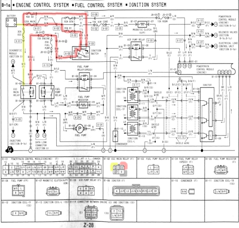
Sorry I'm not familiar with which terminals you're labeling A B C or D, but the wire colors are on the diagram so that should be enough info for you. To answer your question earlier, yes you should read 12V on all three terminals except ground, when the key is turned to the ON position and the relay is in place. Check each terminal compared to the chassis ground (or negative battery post, and then check that ground is actually ground by comparing the black wire to the negative battery post.
Check the following fuses first: B1(40A) and B2 (40A). If you blew a fuse by shorting the wrong terminals, that tells me that your ground should be OK.
Best of luck,
-scott-
PS, most people from the US have never heard the word "dodgy." I've heard some Aussies use it to mean "bad" or usually "substandard" or "crappy." It's likely that 90% of the people on this forum have no idea what it means.
A relay has two parts: the low-power input side, and the high-power output side. Both parts need power and ground to function. If any one of these 4 wires isn't seeing the correct signal, the relay won't function properly. (it's also possible, though not very likely, that you have a mechanical failure inside the relay. if you don't hear the relay 'click' open and closed when you apply power and ground to the low-power input side, then something inside isn't working).
I highlighted the circuit components on the wiring diagram below. On Mazda's drawings, the input to this relay is on the right-hand side (looks like a resistor and an inductor in parallel). The high-power output is the left-hand side (looks like a switch, and the dashed line shows the switch being pulled closed by the magnetic force induced by the inductor).
Sorry I'm not familiar with which terminals you're labeling A B C or D, but the wire colors are on the diagram so that should be enough info for you. To answer your question earlier, yes you should read 12V on all three terminals except ground, when the key is turned to the ON position and the relay is in place. Check each terminal compared to the chassis ground (or negative battery post, and then check that ground is actually ground by comparing the black wire to the negative battery post.
Check the following fuses first: B1(40A) and B2 (40A). If you blew a fuse by shorting the wrong terminals, that tells me that your ground should be OK.
Best of luck,
-scott-
PS, most people from the US have never heard the word "dodgy." I've heard some Aussies use it to mean "bad" or usually "substandard" or "crappy." It's likely that 90% of the people on this forum have no idea what it means.
Last edited by scotty305; Jul 18, 2006 at 11:39 AM.
Thread Starter
Crispy Beef
Joined: Oct 2004
Posts: 134
Likes: 0
From: UK
Bad Ground?
Hi,
Thanks for the reply. I've attached another couple of images to show what I was on about with regards to the A, B, C and D terminals. Was just using the labels that Mazda used on the actual relay description...I think it's page F-101 or something in the FSM.
Do I assume then that the high power input (w/g) should have 12v to it at all times regardless of ignition being on or not? I can't see any reason why when I put a volt meter from that to the neg terminal on the battery I shouldn't read 12v?
The fact that the car runs when I jumper the low power ignition side (b/lg) to the high power output (b/w) suggests the ground is ok?
Both of the 40A fuses (B1 and B2) have continuity and check out, there was a little oxidisation so cleaned those up to be sure.
Duly noted on "dodgy".
Last edited by Crispy Beef; Jul 18, 2006 at 12:14 PM.
Trending Topics
OK, looks like you've got a wiring problem or a failed relay.
A should read 12V when the ignition switch is in the ON position.
B should be 0V (ground) always. When you shorted A>>B, this popped your 15A engine fuse: this is what makes me think that your ground is fine. I'd double-check your B1 and B2 fuses, if you haven't looked at them since you blew the 15A fuse.
C should read 12V always, regardless of key position, even if the relay isn't in place. If not, it's time to look at wiring. You might temporarily install a jumper wire from the fused side of the 30A EGI fuse into the C terminal, to make sure the relay is working.
D should read 12V when the relay is in place and the ignition key is on. Without the relay installed, you'll never see voltage at D.
An easier way to test the wiring would be install a smaller (5A if possible) fuse in place of the EGI (30A) fuse, and just short C>>B. If you blow the fuse, then that narrows the problem down to a bad relay. If the fuse doesn't pop, you've got a wiring problem.
-s-
Last edited by scotty305; Jul 18, 2006 at 12:39 PM.
Rotary Freak
Joined: Jan 2004
Posts: 1,899
Likes: 0
From: tampa
standing on the passenger side of the car with the relay removed
the 2 terminals farthest away..
left is constant 12 v, the one next to it is switched 12 v from the engine fuse and the ignition switch
look if you have no power on the w/g line the egi fuse (which is 30 amp not 40)is blown or the wiring to it is faulty. just because a fuse is ok does not mean that it is necessarly getting power
the wg line is hot at all times C
the b/lg line is hot in run and start only A
the b line is just a ground to complete the controll side of the relay controll B
b/w goes to the ecu etc..D
if you dont have a test light go get one. never just randomly plug jumpers and wires into things. use the correct tools a high impedence test light and you would have narrowed this down in 30 sec.
Last edited by mad_7tist; Jul 18, 2006 at 04:48 PM.
Thread Starter
Crispy Beef
Joined: Oct 2004
Posts: 134
Likes: 0
From: UK
Originally Posted by mad_7tist
if you dont have a test light go get one. never just randomly plug jumpers and wires into things. use the correct tools a high impedence test light and you would have narrowed this down in 30 sec.
Thanks for the information.
Thread Starter
Crispy Beef
Joined: Oct 2004
Posts: 134
Likes: 0
From: UK
Ok, have double checked the B1, B2 (40A) and EGI (30A) fuses and they are all ok, the main ground is ok when testing for continuity also. I've checked out both of my relays - one of which is new - and they both click as expected when voltage is applied correctly so they are ok.
With all that it seems to me that the only possible cause is - as you say - a wiring problem ... and more specifically the wiring between the 30A EGI fuse and the EGI Main Relay. I'll pull those two boxes out again tomorrow and re-check all the wires. I'm hoping it's that as it should be relatively easy to replace.
Thanks for all the suggestions and help. Will let you know what I find.
Cheers.
Thread Starter
Crispy Beef
Joined: Oct 2004
Posts: 134
Likes: 0
From: UK
Originally Posted by mad_7tist
pull out the egi fuse and make sure it has power on one side of it's terminals. that way you know which direction to go (battery to egi / or egi to relay) when looking for the wiring issue
Cheers.
Thread Starter
Crispy Beef
Joined: Oct 2004
Posts: 134
Likes: 0
From: UK
Took out the two fuse boxes today and checked out the wiring, the problem was indeed a bad connection. I put in a new bit of wiring just to be sure, plugged the relay in and she fired up no problem whatsoever.
Thanks guys for the tips.
I still have the three lights - coolant, oil and charge - lit on the dash however, could this still be the alternator even though I've had it checked out? I've read on the forums elsewhere that people have had their alternators check out but when putting a new one in it's cured the problem. With the engine running the correct voltages are going to the alternator terminals. Guess it might be a new unit?

Thread
Thread Starter
Forum
Replies
Last Post
ls1swap
3rd Generation Specific (1993-2002)
17
Jun 3, 2024 03:25 PM
FC3S Timmy
2nd Generation Specific (1986-1992)
16
Oct 3, 2015 01:08 AM