
Custom replacement solenoid system

-m = Molded coil option gives you 221F max operating temp.-h = Hi temp option gives you 356F max operating temp. I still dont think thats good enough for under the manifold. If there are other options I dont see them on fabcoairs website. Here is the link, bottom of first page.
Solenoid, Coil and Housing InformationDirectional Control Valves 53 Style
53 STYLE Options for 53 STYLE Options for Yoke Housing
Conduit Housing �C� and � Yoke with Standard coil
grommet Housing �g� (24" flying leads) . . . . . . . . . . . . . . . . . . . . . . . . . . Option -YB
AC Voltages from 5.4 to 575 in 50 or 60 Hertz. � Yoke with Molded coil
DC Voltages from 3 to 300. (24" flying leads) . . . . . . . . . . . . . . . . . . . . . . . . . . Option -YM
� Yoke with Molded
Spade Terminal and coil . . . . . . . . . . . . . . . . . . . .Option -kM
� Molded Coil . . . . . . . . . . . . . . . . . . . . . . . . . .Option -M
Water tight, Molded Coil with Class A 221�F Yoke replaces housing
(105�C) Rating. Coil is completely molded in for protected and control box
epoxy for maximum moisture resistance. applications. Molded coil with 1.67
two .25" spade terminals for .60 .33
NEMA 1, 2, and 3 when in
quick assembly and
Conduit �C�, or Grommet �G� housing. 1.03 .60
disconnect.
� Potted Coil . . . . . . . . . . . . . . . . . . . . . . . . . . . Option -P 10-32 .25 x .03 Thick
Coil is epoxy potted into Conduit �C� housing only. Exhaust
Port
Class F 221�F (105C) Rating. 1.50 Flying Leads Coil
It offers maximum moisture and vibration resistance. 1.74 Spade Coil
NEMA 3R, 3S, 4, 4X, 6, 11, 12 & 13.
� High Temperature . . . . . . . . . . . . . . . . . . . . . Option -H
Molded coil with 356�F (180�C) rating.
� Viton Seals 53 STYLE Explosion Proof . . . . . . . . Option -EP
(for media compatibility) . . . . . . . . . . . . . . . Option -V UL File #E37780
CSA File #LR-26894
� Strain Relief Connector . . . . . . . . . . . . . . . . . Option -Q For hazardous locations, includes Molded Coil.
� �AN� Connector . . . . . . . . . . . . . . . . . . . . . . Option -W UL Class I Div. 1 Groups C & D.
UL Class II Div. 1Groups E, F & G.
� Splice Box . . . . . . . . . . . . . . . . . . . . . . . . . . Option -J
UL Class II Div. 2 Groups A, B, C, D, E & F.
� Mounting Bracket . . . . . . . . . . . . . . . . . . . . . Option -R NEMA 7 Class 1 Group D.
NEMA 9 & 9A Class II Groups F & G.
� Third Wire Ground . . . . . . . . . . . . . . . . . . . .Option -CC 1/2 NPT
A CSA requirement.
! CAuTiON !
1.44
To prevent explosion,
disconnect electrical circuit 10-32 1.53 11
Exhaust
before opening enclosure! Port
53 STYLE Options for Keep tightly closed when 1.60
Male Mini-diN Housing �F� in operation.
.75
AC Voltages from 4.4 to 277 in 50 or 60 Hertz. Option -EP Current Factors Housing can rotate 360�
DC Voltages from 3 to 180.
AC Volts, 60 Hertz Inrush . . . . . . . . . . . . . Holding
2 Way NC 16.0 . . . . . . . . . . . . . . . . . . 7.8
� Viton Seals 2 Way NO 16.9 . . . . . . . . . . . . . . . . . 10.7
(for media compatibility) . . . . . . . . . . . . . . Option -V 3 Way NC or NO 16.9 . . . . . . . . . . . . . . . . . 10.7
DC Volts Inrush or Holding
2 Way NC or NO 7.2
3 Way NC or NO 7.2
Divide �Factor� shown above by Volts to find current.
See examples on opposite page.
11.30
3-3-08 Specifications subject to change without notice or incurring obligation


Junior Member
Joined: Dec 2009
Posts: 17
Likes: 0
From: California
Well to date they have worked flawlessly. I think the only real downside is that you have to run longer vacume lines that may reduce responsiveness but i realy cant tell. I ended up running realys for each as they are very hevy duty and their wasent enough jucie to reliably switch them. I think the best part is the ability to diagnose problems without ripping off the uim. You simpy unplug all but one then turn the key on and listen for it click then move to the next. Its accually how i managed to fix my boost problem they had the pressure hose and the vacume hose swaped at the acuator so when i was manually triggering them it did nothing and i went from their. As far as the solenoids go i bought them off of ebay new, they are for big rigs not really sure for what though rated to 30psi, 180f and have viton seals. i was initially worried about the temp rating but where i have them mounted i can touch them after a long drive and the are just alittle warm (120 according to my temp gun) and was as hot as ive seen them go.


Has anyone tried mounting them directly behind the UIM on the firewall? Still pretty accessible with a little lower back pain and you wouldn't have such a huge increase in the hose length. could always fab up a little heat shield under them as well to keep heat away.
Junior Member
Joined: Dec 2009
Posts: 17
Likes: 0
From: California
The solenoids i have are to large to fit behind the uim. The lenght of the vacume hoses is minimal as far as i can tell. As sad as it is my system never worked with stock solenoids and the only other FD ive ridden in was non-sequential so i couldent really tell if their is a difference in lag.
Thats probably where im going to mount mine. The pics I posted were my buddies 7. In a few months ill pick up some solenoids and see what I can come up with. Maybe ACV and all the garbage on the firewall and all turbo solenoids where I have them mounted now. Might be pretty clean.
i'm so glad somebody dug up this old thread! i searched for it for about a month at one time, i have an original set that Rob made. they will be going on the car in the very near future!
subscribed so i don't loose it again and see if someone modifies the design
subscribed so i don't loose it again and see if someone modifies the design

Full Member
Joined: Jan 2010
Posts: 143
Likes: 6
From: Idaho
Dem I wish some one would come out with a kit some time soon. I need to replace some of my stock solenoids and I really dont want to go back to stock solenoids. I feel like it would be a waste of money.
This seems to sit in limbo because most people go from stock straight to single turbos.
BNR are the only folks I think that would profit from designing a system like this to work with their stage 3's.
BNR are the only folks I think that would profit from designing a system like this to work with their stage 3's.

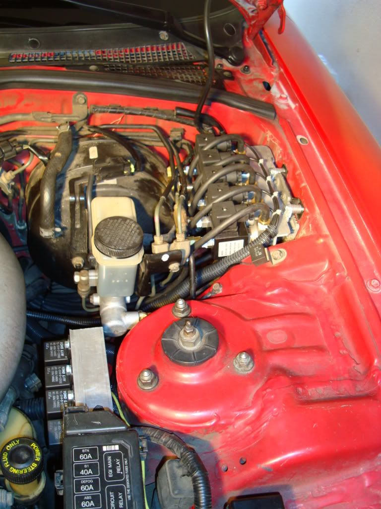
Here are some pics of where mine was mounted before I went single this winter.
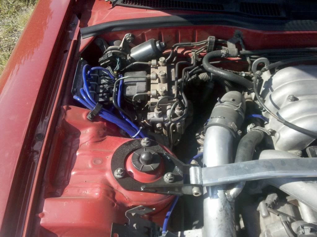
Clean, out of the way, and unobtrusive. The response was phenomenal and crisp, I loved it until I lost the corner of one of my apex seals.
Clean, out of the way, and unobtrusive. The response was phenomenal and crisp, I loved it until I lost the corner of one of my apex seals.
Joined: Jun 2005
Posts: 1,487
Likes: 0
From: Vacaville, California
Joined: May 2005
Posts: 3,243
Likes: 42
From: Kennewick, Washington
probably not