
Custom cold air NACA duct project

It is nice to see this kind of thought process go into making a part, good for you it looks nice! Personally I was thinking more along the lines of taking the NACA duct idea and bringing it towards the bumper opening  but maybe you have a stock bumper so you don't have the space.
but maybe you have a stock bumper so you don't have the space.
Originally Posted by NissanConvert
Do you have a general idea of your IATs? Power? Anything like that so we can compare before and after on something other than the butt dyno?

Originally Posted by dradon03
Personally I was thinking more along the lines of taking the NACA duct idea and bringing it towards the bumper opening but maybe you have a stock bumper so you don't have the space.

Also, my springs, tires, and wheels arrived this week, can't wait to get them out of my apartment and on the car!!!

Last night I layed up 2 layers of 1.5oz csm on the top of the box. I guess I'll just do the sides two at a time to ensure even coats and good adhesion around the corners.
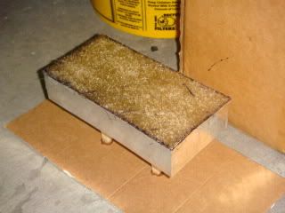
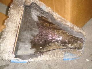
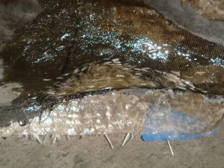
I also had to fill a low point on the duct. I didn't have any reinforced filler, so I made some with an oz of poly resin and 1/4" chopped strands. I mixed it up thick and it worked pretty well.
Hopefully finishing up this weekend so I can move on to new parts.
I also had to fill a low point on the duct. I didn't have any reinforced filler, so I made some with an oz of poly resin and 1/4" chopped strands. I mixed it up thick and it worked pretty well.
Hopefully finishing up this weekend so I can move on to new parts.

Duly noted, and I have worried about this too. However, I daily drive my FX, so the RX only sees dry conditions (in Los Angeles, to boot). Air enters into the lower chamber of the airbox and passes up through the panel filter. Thus, any water that enters will be below the filter panel and will simply drain out the small drainage holes I put in the bottom of the airbox.
You could use the same NACA ducting technique with ducts behind the openings in the R1 lip and find a way to route it to your brakes... just an idea. Also I wouldn't worry about water, when traveling at speed the air around the car means that the water isn't falling straight into the duct.
That's pretty much what I intend to do! The last time I barreled down the canyons West of LA my brake pads were literally smoking at the bottom.
If you decide to go with an aftermarket bumper you will begin to be able to explore your imaginations potential.


EDIT- BTW nice thread! reminds me of the old days when this section was actually interesting.


Intake temps are logged on my AEM EMS. I will be able to pull the difference in temps from there. However, I'm not really looking to make power with this mod, per se... I just don't see any reason why the stock airbox should be drawing air away from the intercooler duct, and vice versa. Also, I don't want to just plop some open filters in there that draw in hot air from the engine bay. Also, I'm just having fun

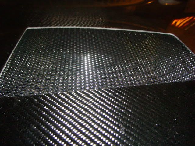
mono4lamar: The bigger openings are for hot air ventilation. I bought some black powdercoated hexagon expanded metal from this site. However, later, I may sculpt in a duct aligned to the back of a new intercooler, but that's a project for another day.
Big thanks to everyone following this thread! I got some time to work on this over the weekend, almost there...
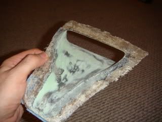
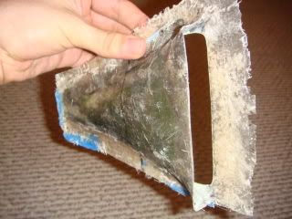
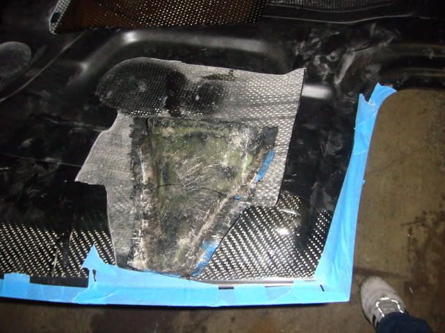
It finally looks like a duct. The green stuff is Rage Gold body filler, only the best... I sanded it to a smooth finish with 320 grit, but after I painted it, I think I may have to go back and fill/sand a little more.
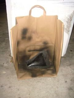
Priming in my ghetto paint booth.
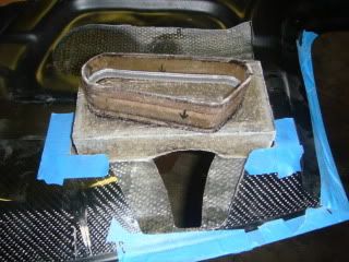
Back on the hood, things are stacking up. The box and collar fitted to the hood w/o the duct. It's hard to see, but I adhered a ring of weatherstripping inside of the collar to rest up against the airbox inlet when the hood is shut. This seals off the ducting to any engine air. Do you think it would help to wrap the ducting with heat-resistant materials?
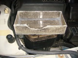
The box and collar fitted to the air inlet w/o the hood. I used silicone to seal the inside edges of the box. Are all these pictures overkill?
With the hood shut, you can see how the air will flow into the box through the ducting still in the ghetto paint booth.
All that's left to do is permanently attach the duct to the hood, the box to the duct, and the collar to the box. The whole lot fits to the hood now and aligns with the airbox inlet as the hood shuts.
Big thanks to everyone following this thread! I got some time to work on this over the weekend, almost there...
It finally looks like a duct. The green stuff is Rage Gold body filler, only the best... I sanded it to a smooth finish with 320 grit, but after I painted it, I think I may have to go back and fill/sand a little more.
Priming in my ghetto paint booth.
Back on the hood, things are stacking up. The box and collar fitted to the hood w/o the duct. It's hard to see, but I adhered a ring of weatherstripping inside of the collar to rest up against the airbox inlet when the hood is shut. This seals off the ducting to any engine air. Do you think it would help to wrap the ducting with heat-resistant materials?
The box and collar fitted to the air inlet w/o the hood. I used silicone to seal the inside edges of the box. Are all these pictures overkill?
With the hood shut, you can see how the air will flow into the box through the ducting still in the ghetto paint booth.
All that's left to do is permanently attach the duct to the hood, the box to the duct, and the collar to the box. The whole lot fits to the hood now and aligns with the airbox inlet as the hood shuts.

Some of the plugs were lost by design, but the whole underhood system is easily replicable from the finished product.
Ok... So I finished up with this project and some of the elements turned out great, while others failed. The whole induction thing? Not happening... In the end, the whole deal looked to restrictive, as others had feared. And after witnessing the velocity at which air enters the relatively small mouth of the airbox, I realize now that open elements are the way to go. So, I'm going to build an M2 style air box with twin cylindrical air elements for the intake tubes. I have another stock airbox which I am going to modify for this project. The NACA duct actually turned out great, so that will now be feeding the yet to be completed airbox with a much more direct flow than before. Stay tuned...
CA glued to the hood.
You can also see some weatherstripping I added to close the gap between the front of the hood and the bumper. Air was getting in there and trying to force the hood up, but not any longer...
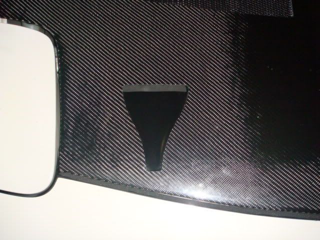
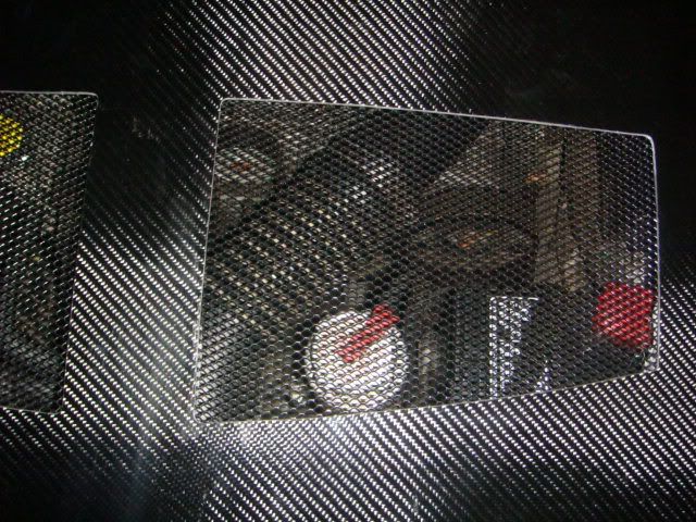
The hex perf metal screens are angled such that air should flow directly over the top to help "pull" hot air from the engine bay below. Viewed from above, it's 63% open area.
CA glued to the hood.
You can also see some weatherstripping I added to close the gap between the front of the hood and the bumper. Air was getting in there and trying to force the hood up, but not any longer...
The hex perf metal screens are angled such that air should flow directly over the top to help "pull" hot air from the engine bay below. Viewed from above, it's 63% open area.

I bought it from Custom Car Grills.com
This thread is evolving into an all inclusive "TimeMachine" projects/build thread (in lieu of starting new threads for each project); and, if a mod could alter that thread title for me that would be great, thx
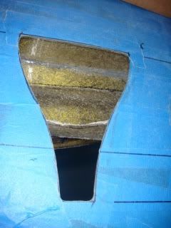
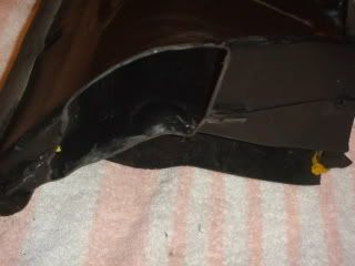
Over the last weekend I had a chance to fix the stock intercooler duct. I patched the hole for the stock intake box and cut off the A/C duct and patched that. I was feeling super lazy, so that's why I used some flat fiberglass panels I had lying around instead of 'glassing the duct like a normal person... They are CA glued in place and further sealed with silicone. Now, all the flow from the stock duct goes to the smic.
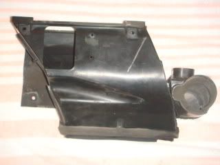
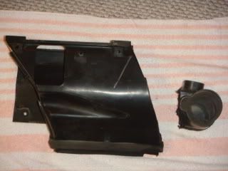
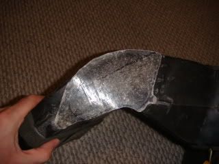
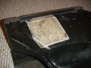
Next up is modding the airbox to accept two cylindrical K&N filters fed by the NACA duct and allowing the radiator some room to breathe.
Over the last weekend I had a chance to fix the stock intercooler duct. I patched the hole for the stock intake box and cut off the A/C duct and patched that. I was feeling super lazy, so that's why I used some flat fiberglass panels I had lying around instead of 'glassing the duct like a normal person...
They are CA glued in place and further sealed with silicone. Now, all the flow from the stock duct goes to the smic.Next up is modding the airbox to accept two cylindrical K&N filters fed by the NACA duct and allowing the radiator some room to breathe.

Thread
Thread Starter
Forum
Replies
Last Post
82streetracer
1st Generation Specific (1979-1985)
7
Aug 23, 2015 09:28 AM