
Cooling fans question

Thread Starter
Now,Hit it with a hammer!
iTrader: (1)
Joined: Jul 2014
Posts: 46
Likes: 0
From: Boulder, Colorado
Cooling fans question
So, I've been working on getting my 7 in top running condition. My Mod Thread I've invested my time with Reliability mods, etc. The motor was replaced at a mazda dealer(previous owner) about 20k miles ago, along with the clutch. I've replaced the full exhaust with the B�nez 3" exhaust(downpipe, plus mid pipe with single cat, so I can meet emissions), 3 inch racing beat cat back, AST delete, walbro 255 fuel pump, adjusted TPS, plugs/wires, cleaned/updated some grounds and recently added a set of gauges(autometer Phantom 1 voltmeter/mechanical boost gauge and phantom ii coolant temp gauge(sender installed in front of the thermostat housing)).
With the new gauge, I've noticed the coolant temps and seems to be pretty accurate ~1�. Everything seems to be fine, except when the car starts to heat soak(around town driving). With the running lights/AC off, I've noticed it can get up to 235� driving around and the fans don't seem to come on. I'm paranoid(due to me reading somewhere that they should normally come on at 225�), so I turn on my running lights, which causes the fans to kick on and continue to kick on at 225� Down to 210� where they will kick off. If I turn on the a/c and the running lights, the fans kick on high and temps as low as 188�-190� Can be seen, very fast. I've been in ~70�F ambient temps. I switched around the relay to see if that could be an issue(between the a/c relay and thermistor relay).
Now, here is the 64 dollar question. I notice a lot of people swapping over to the fc thermistor for the fans. Does this seem like the next action to take or am I possibly missing something/overreacting? Also, I was thinking of replacing the other temp sensor above it, Whilst I'm there(which is for the stock temp gauge/Ecu?). I need to change my belts, so it will give me a reason to tear the car apart....again.....lol


235 F. is dangerously hot IMO. I imagine some of that may be due to the altitude where you live, but yes, I think my next step would be to swap the stock thermoswitch out for the S5 FC version. That should kick the fans on low at something like 203 F. (95 C) instead of 226 F. (108 C). A second input, like A/C, and IIRC the rear defogger, should kick the fans up a speed from that.
Without reading through your mod thread, other things that help would be to run as much distilled water to coolant as you can get away with. Install the second oil cooler if you don't have one and stuff upholstery foam in any gaps around the radiator face. Consider a simple WI system after that.
Without reading through your mod thread, other things that help would be to run as much distilled water to coolant as you can get away with. Install the second oil cooler if you don't have one and stuff upholstery foam in any gaps around the radiator face. Consider a simple WI system after that.
Thread Starter
Now,Hit it with a hammer!
iTrader: (1)
Joined: Jul 2014
Posts: 46
Likes: 0
From: Boulder, Colorado
235 F. is dangerously hot IMO. I imagine some of that may be due to the altitude where you live, but yes, I think my next step would be to swap the stock thermoswitch out for the S5 FC version. That should kick the fans on low at something like 203 F. (95 C) instead of 226 F. (108 C). A second input, like A/C, and IIRC the rear defogger, should kick the fans up a speed from that.
Without reading through your mod thread, other things that help would be to run as much distilled water to coolant as you can get away with. Install the second oil cooler if you don't have one and stuff upholstery foam in any gaps around the radiator face. Consider a simple WI system after that.
Without reading through your mod thread, other things that help would be to run as much distilled water to coolant as you can get away with. Install the second oil cooler if you don't have one and stuff upholstery foam in any gaps around the radiator face. Consider a simple WI system after that.
Good to know about the defogger. I will give it a shot tomorrow.
It is starting to get colder and I have roughly 60% water.
My oil cooler is stock, but I looked at it today and looks like half of the fins have been slightly damaged from rocks over the past few years. I may rebuild it one day but will straighten the fins for now, as this car doesn't see track time. Not to mention, the fan is not working correctly, so I will start with that.

I'll check into the foam! I saw something on this earlier today.

That is very strange as you should have 4 fan speeds , 1 thermostiwch which turns on at around 108 C 226F
it looks like you are running teh stock ECU so I THINK the stock ECU starts to turn the fans on first stage at 100C which is 212 ,
I'm not sure when the next stage is But as for relays
1 Relay works for the first stage first speed ,
2 relay is second speed
3 relay works with the Thermoswitch ( reinforces grounds )
4 relay is the AC relay which is Different from the other 3 .
it seems to me that your 1/2 speed relays may be bad . Try tricking the relays to see if you can get the fans to turn on , in the FAQ there is a great writeup on the fans .
look into it and study it and then try to figure out the problem . if your fans are not turning on at that temp until you turn on the AC
Then I'm 100% sure its your 1/2 speed fan relays .
Because at 108C when the thermoswitch relay goes off , what it does is reinforce grounds . if its not receiving any positive current from the 1/2 relays then that ground goes to waste .
But when you turn on the AC the AC relay sends some positive current to the fans , and thus the thermoswitch relay is already running and you get the fans running at second speed .
total speed of the Fans is 4 , 1 from the AC , 1 from each of the temp switches controlled by the ECU , and one reinforced ground relay controlled by the thermoswitch .
Upgrading the thermoswitch will do nothing if its not getting current from the other relays .
Thread Starter
Now,Hit it with a hammer!
iTrader: (1)
Joined: Jul 2014
Posts: 46
Likes: 0
From: Boulder, Colorado
That is very strange as you should have 4 fan speeds , 1 thermostiwch which turns on at around 108 C 226F
it looks like you are running teh stock ECU so I THINK the stock ECU starts to turn the fans on first stage at 100C which is 212 ,
I'm not sure when the next stage is But as for relays
1 Relay works for the first stage first speed ,
2 relay is second speed
3 relay works with the Thermoswitch ( reinforces grounds )
4 relay is the AC relay which is Different from the other 3 .
it seems to me that your 1/2 speed relays may be bad . Try tricking the relays to see if you can get the fans to turn on , in the FAQ there is a great writeup on the fans .
look into it and study it and then try to figure out the problem . if your fans are not turning on at that temp until you turn on the AC
Then I'm 100% sure its your 1/2 speed fan relays .
Because at 108C when the thermoswitch relay goes off , what it does is reinforce grounds . if its not receiving any positive current from the 1/2 relays then that ground goes to waste .
But when you turn on the AC the AC relay sends some positive current to the fans , and thus the thermoswitch relay is already running and you get the fans running at second speed .
total speed of the Fans is 4 , 1 from the AC , 1 from each of the temp switches controlled by the ECU , and one reinforced ground relay controlled by the thermoswitch .
Upgrading the thermoswitch will do nothing if its not getting current from the other relays .
it looks like you are running teh stock ECU so I THINK the stock ECU starts to turn the fans on first stage at 100C which is 212 ,
I'm not sure when the next stage is But as for relays
1 Relay works for the first stage first speed ,
2 relay is second speed
3 relay works with the Thermoswitch ( reinforces grounds )
4 relay is the AC relay which is Different from the other 3 .
it seems to me that your 1/2 speed relays may be bad . Try tricking the relays to see if you can get the fans to turn on , in the FAQ there is a great writeup on the fans .
look into it and study it and then try to figure out the problem . if your fans are not turning on at that temp until you turn on the AC
Then I'm 100% sure its your 1/2 speed fan relays .
Because at 108C when the thermoswitch relay goes off , what it does is reinforce grounds . if its not receiving any positive current from the 1/2 relays then that ground goes to waste .
But when you turn on the AC the AC relay sends some positive current to the fans , and thus the thermoswitch relay is already running and you get the fans running at second speed .
total speed of the Fans is 4 , 1 from the AC , 1 from each of the temp switches controlled by the ECU , and one reinforced ground relay controlled by the thermoswitch .
Upgrading the thermoswitch will do nothing if its not getting current from the other relays .
I have not found anything pertaining to 100C /212F as the first stage of the fans. What I HAVE found is 105-108C / 221-226F as the first stage according to the chart.
-Relays 2 & 4 are connected to the ECU. Stock they are triggered at 105 C and bump up the speed by one level.
-Relay #1 is the A/C trigger. This relay bumps the fan speed up one level
--- Relay #3 is connected to the thermoswitch and is triggered at 108 C stock. This relay bumps the fan speed up one level.
What I did notice, after research today, was that I made a mistake while switching the relays around. I switched #2 and #4 around....which run in parallel. I didn't test the thermistor relay, as planned. This was due to the lack of Internet and poor memory.... :\ I will test to see if I can jump the relay connectors, making the fans kick on. I will report back tomorrow when there is day light.

IIRC about the a/c, I can start the car from a cold start, click the a/c on, and the fans will kick on immediately. And continue to run all the time. I will double check this tomorrow.
For the fans to act normally, I just turn on my running/headlights lights......which, according to the chart, at 226ish should be medium fan speed.(relay 2-4-3) but sounds like low speed. I could be wrong.
Ps: I have a stock ECU. I cannot justify an expensive unit like that, if the fix it a ~60$ sensor and I have minor mods.
OK, I guinea pigged this one, and all worked out for the best .
As you may recall, I posted a while back that I saw in a copy of RX-7 Magazine from Japan that they were using the '89-91 FC thermoswitch as an upgrade. This jogged my thinking...well, fast forward to today. I got the thermoswitch last week and installed it today.
Here's the deal -
- SAME operating specs as the Miata switch
- BUT, uses the stock FD plug - NO CUTTING OR HACKING. Unscrew old switch, screw this one in, plug it in, you're done.
It was about $50 from Ray Crowe at Malloy Mazda (1-888-544-3400). He didn't have it in stock, so it took a day or two for him to get it and ship it my way. But, I explained the deal with the switch to him, and he was VERY interested - I think if he gets an order or two, this will be a stocked item soon. Part number is PN41-18-840. It's for the '89-91 RX-7, non-turbo or turbo.
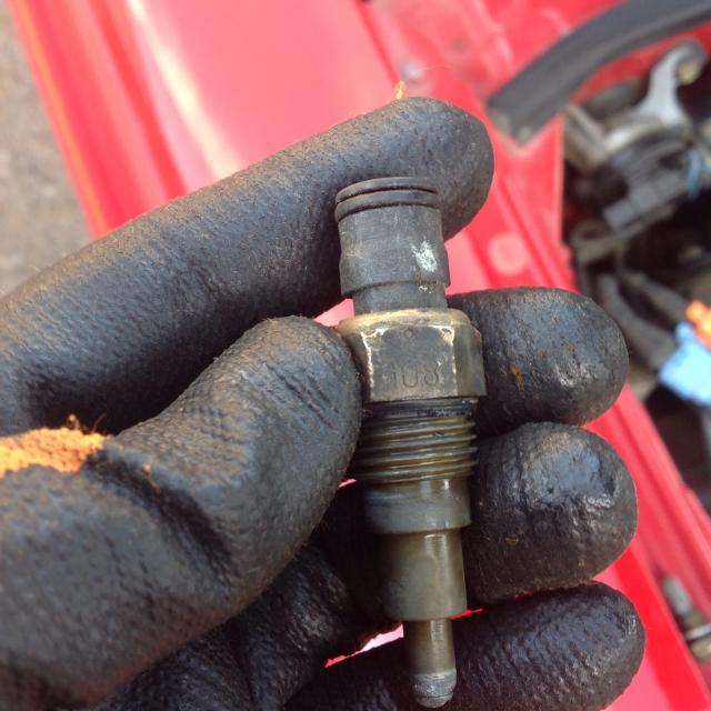
Dunno if you can see on the pics, but the FD switch has "108" on it, and the FC switch has "95" stamped on it. That's the switch-on temps - 95 deg. C and 108 deg. C. Fans come on sooner, car stays cooler, engine stays happier.
It was a little bit of work to install. I removed the crossover pipe and alternator, then had access. Unplugged the old switch (you have to hunt for the "button" to unlatch the connector - it was on the under side of mine), used a 17mm closed-end wrench to break it loose, then unscrewed it. Some water was lost, but it was just water in the top of the thermostat housing. Put a little oil on the O-ring on the new switch (came with the switch, and it was already on there) and screwed it in. Plugged everything back together, put the car back together, good to go. Pulling the alternator was the most time consuming part - it's a little tricky to get out of there.
Anyhow, this is a done deal - the Miata thermoswitch is now a "dead mod". Unless it's WAY the hell cheaper or something. I'd much rather have one that plugs right in just like stock!
Dale
.As you may recall, I posted a while back that I saw in a copy of RX-7 Magazine from Japan that they were using the '89-91 FC thermoswitch as an upgrade. This jogged my thinking...well, fast forward to today. I got the thermoswitch last week and installed it today.
Here's the deal -
- SAME operating specs as the Miata switch
- BUT, uses the stock FD plug - NO CUTTING OR HACKING. Unscrew old switch, screw this one in, plug it in, you're done.
It was about $50 from Ray Crowe at Malloy Mazda (1-888-544-3400). He didn't have it in stock, so it took a day or two for him to get it and ship it my way. But, I explained the deal with the switch to him, and he was VERY interested - I think if he gets an order or two, this will be a stocked item soon. Part number is PN41-18-840. It's for the '89-91 RX-7, non-turbo or turbo.
Dunno if you can see on the pics, but the FD switch has "108" on it, and the FC switch has "95" stamped on it. That's the switch-on temps - 95 deg. C and 108 deg. C. Fans come on sooner, car stays cooler, engine stays happier.
It was a little bit of work to install. I removed the crossover pipe and alternator, then had access. Unplugged the old switch (you have to hunt for the "button" to unlatch the connector - it was on the under side of mine), used a 17mm closed-end wrench to break it loose, then unscrewed it. Some water was lost, but it was just water in the top of the thermostat housing. Put a little oil on the O-ring on the new switch (came with the switch, and it was already on there) and screwed it in. Plugged everything back together, put the car back together, good to go. Pulling the alternator was the most time consuming part - it's a little tricky to get out of there.
Anyhow, this is a done deal - the Miata thermoswitch is now a "dead mod"
. Unless it's WAY the hell cheaper or something. I'd much rather have one that plugs right in just like stock!Dale
infact I dont even run a thermoswitch I have mine eliminated and the relay jumped , since it only works with a ground asoon as the first ECU controlled Fan stage triggers its automatically in speed 2 the ECU controls 2 of the speeds .
as for WHAT temp they turn on I dont know LOL I've never used a stock ECU . But with the Power FC thats how it works .
the Thermoswitch works with ground as the temp hits 108C it passes a ground to the thermoswitch relay , and that again reinforced the ground to the fans . which triggers an extra speed .
the ECU relays work with with signals from the ECU
now what the thermoswitch will do is when the other fans turn on it will kick in at a higher speed at over 95C rather then 108C <-- which is pretty hot as it is .
Trending Topics
Some good resources....
https://www.rx7club.com/3rd-generati...system-906142/
https://www.rx7club.com/3rd-generati...system-906142/
Of course, you could always just drive faster
https://www.rx7club.com/3rd-generati...system-906142/
https://www.rx7club.com/3rd-generati...system-906142/
Of course, you could always just drive faster
Thread Starter
Now,Hit it with a hammer!
iTrader: (1)
Joined: Jul 2014
Posts: 46
Likes: 0
From: Boulder, Colorado
So, I went and rotated the 3 similar relays(not the a/c one). I got the same results, no matter the combination. When the lights/defroster/AC are off, the fans just will NOT come on. What I do know, is that when the lights/defroster are on, the fan speed is medium speed. I unplugged the thermistor(relay #3) relay first, and the fan kicked down to low speed. Same with Ecu relay #4 unplugged, with the thermistor relay plugged in. If I pulled the #2 relay out whilst the fans were on(both #3/#4 plugged in), nothing would happen to speed, no matter what configuration the relays were in.
Now, my question is, what signal does the Ecu/Ecu relays(2&4) rely on? My guess is one is the temp Ecu switch above the thermistor and the other is the ELD. Not to mention, I think I read the ELD is spliced into wiring to the thermistor relay. I will look at the wiring diagram and see, just to make sure. It could just be spliced into the wiring to the relay...... Either way, I am going to order both sensors, just because they seem to need to be changed/updated, anyway.
Now, my question is, what signal does the Ecu/Ecu relays(2&4) rely on? My guess is one is the temp Ecu switch above the thermistor and the other is the ELD. Not to mention, I think I read the ELD is spliced into wiring to the thermistor relay. I will look at the wiring diagram and see, just to make sure. It could just be spliced into the wiring to the relay...... Either way, I am going to order both sensors, just because they seem to need to be changed/updated, anyway.
https://www.rx7club.com/3rd-generati...ntrols-876767/ this is my fav cooling thread it explains everything prettymuch
Thread Starter
Now,Hit it with a hammer!
iTrader: (1)
Joined: Jul 2014
Posts: 46
Likes: 0
From: Boulder, Colorado
https://www.rx7club.com/3rd-generati...ntrols-876767/ this is my fav cooling thread it explains everything prettymuch
But neither answer my question and I'm not the best with wiring diagrams. They say the #2/#4 relays run in parallel and kick on the fans at 105C. I got that the first time I Read it. But, My car's fans are not kicking on at 105C. So, that leads me to the question: where does the Ecu get the information (the 105c temp) For it to kick on the relays/fans? I was thinking it was the Ecu temp sensor above the thermistor but could be a number of things, I presume. I'm trying to Figure out if there is a issue between the relays to the Ecu or from the Ecu to the sensor, etc. Be it wiring, grounds, faulty Ecu, faulty temp sensor, etc. I know the fans are ok, as I've engaged all 3 speeds. I know the relays seem to be fine, as I've gotten them all to click and work. I noticed that the relay slot for #2 is doing nothing when relay is remove whilst the fans are on.....and I have a gut feeling that this is my issue. I could be completely wrong, though.
I've been injured with a herniated disc, so I can barely lean over a car for longer than a couple minutes at a time.....but by god I haven't met a competent mechanic in my life(if they are, there is a reason to their high prices)....that is the reason I became one at one time....and that is the reason I am trying to be thorough. Less time over the car=shorter healing time. Thanks for the replies! I will update with my findings when they surface.
I've read that at least 20 times....it is informative. I like the daleclark one better, as it is more direct.
But neither answer my question and I'm not the best with wiring diagrams. They say the #2/#4 relays run in parallel and kick on the fans at 105C. I got that the first time I Read it. But, My car's fans are not kicking on at 105C. So, that leads me to the question: where does the Ecu get the information (the 105c temp) For it to kick on the relays/fans? I was thinking it was the Ecu temp sensor above the thermistor but could be a number of things, I presume. I'm trying to Figure out if there is a issue between the relays to the Ecu or from the Ecu to the sensor, etc. Be it wiring, grounds, faulty Ecu, faulty temp sensor, etc. I know the fans are ok, as I've engaged all 3 speeds. I know the relays seem to be fine, as I've gotten them all to click and work. I noticed that the relay slot for #2 is doing nothing when relay is remove whilst the fans are on.....and I have a gut feeling that this is my issue. I could be completely wrong, though.
I've been injured with a herniated disc, so I can barely lean over a car for longer than a couple minutes at a time.....but by god I haven't met a competent mechanic in my life(if they are, there is a reason to their high prices)....that is the reason I became one at one time....and that is the reason I am trying to be thorough. Less time over the car=shorter healing time. Thanks for the replies! I will update with my findings when they surface.
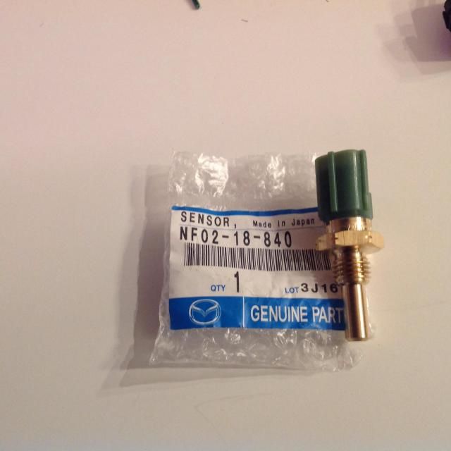
it gets the signal from the water temp sensor behind the thermostat housing . I believe the plug is green. its about 20 dollars in an auto parts store . for the sensor ( friend of mine had to get one )
its not a difficult job to replace but because of your health issues I would suggest a helping hand as you would need to do some leaning over for a bit .

Or another option might be to spring for the cost of a t-stat housing gasket, coolant and some anti-seize to remove the housing and replace the sensors. Maybe even a good time to replace the t-stat. And a little less bending in the limited space to "build the ship in a bottle".
If you're going thru the trouble to replace the T-stat and temp sensor, replace with the 185 deg ones. That may not solve your problem, but when you do solve it, you'll have a better T-stat and sensor.
Thread Starter
Now,Hit it with a hammer!
iTrader: (1)
Joined: Jul 2014
Posts: 46
Likes: 0
From: Boulder, Colorado
it gets the signal from the water temp sensor behind the thermostat housing . I believe the plug is green. its about 20 dollars in an auto parts store . for the sensor ( friend of mine had to get one )
its not a difficult job to replace but because of your health issues I would suggest a helping hand as you would need to do some leaning over for a bit . good luck and hope its just that sensor
its not a difficult job to replace but because of your health issues I would suggest a helping hand as you would need to do some leaning over for a bit .
Or another option might be to spring for the cost of a t-stat housing gasket, coolant and some anti-seize to remove the housing and replace the sensors. Maybe even a good time to replace the t-stat. And a little less bending in the limited space to "build the ship in a bottle".

Thread Starter
Now,Hit it with a hammer!
iTrader: (1)
Joined: Jul 2014
Posts: 46
Likes: 0
From: Boulder, Colorado
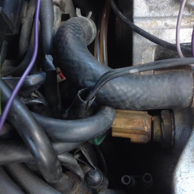
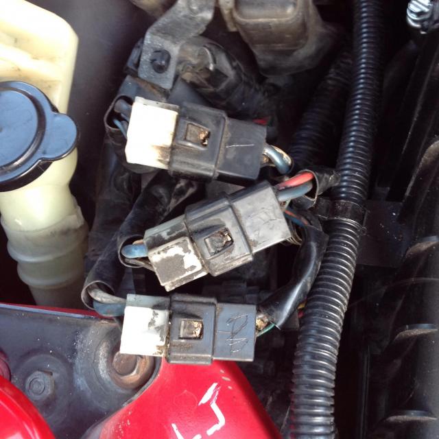
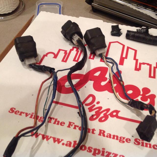
So, I ordered the parts and decided to get a head start on taking it apart. And I think I found both of my issues.
1 the Ecu temp sensor was cracked/separated.
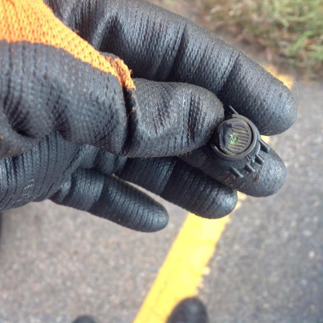
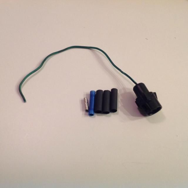
2 the wire going into the clip for the fan thermistor was corroded and had broke off. I need to find a replacement clip and pig tail, if possible. Anyone know a good place? I will start searching now.
Ecu temp
Thermistor clip
Thermistor
Also, I did not have to remove the alternator, I am crafty with removing things.
1 the Ecu temp sensor was cracked/separated.
2 the wire going into the clip for the fan thermistor was corroded and had broke off. I need to find a replacement clip and pig tail, if possible. Anyone know a good place? I will start searching now.
Ecu temp

Thermistor clip

Thermistor

Also, I did not have to remove the alternator, I am crafty with removing things.
Thread Starter
Now,Hit it with a hammer!
iTrader: (1)
Joined: Jul 2014
Posts: 46
Likes: 0
From: Boulder, Colorado
Got all the new parts in today! Ray Crowe sent the parts promptly and cheaper than the local mazda joint.
FC Thermistor/Thermoswitch
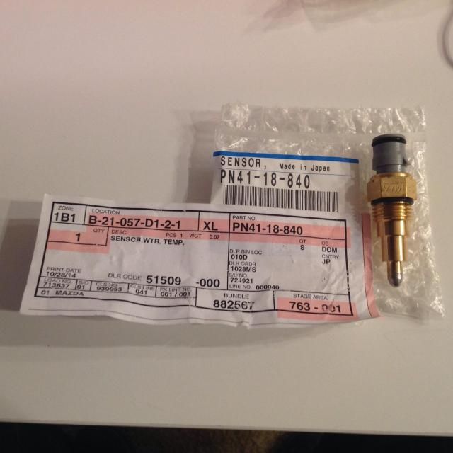
FD ECU Temp Sensor
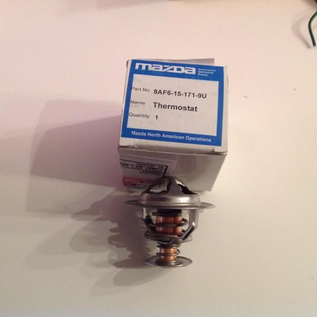
New mazda Thermostat(should I remove the jiggy?)
Also, got a connector with pigtail from a rx7club member! He even sent me some butt connectors and heat shrink.
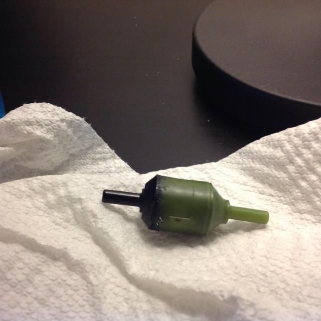
Also, I repaired my vacuum check valve. Works great with no leaks. I put a small piece of foam inside from a boost gauge filter that broke on me. Works great. The black cap looked to have been glued to the green part in the first place. So I used some Blue locktyte(which didn't melt the plastic) in the groove and pressed it back together. Then I used my extra,cheap, sauldering gun and heated up the seam between the two plastics. Voil�. Not pretty, but works.
FC Thermistor/Thermoswitch

FD ECU Temp Sensor

New mazda Thermostat(should I remove the jiggy?)

Also, got a connector with pigtail from a rx7club member! He even sent me some butt connectors and heat shrink.

Also, I repaired my vacuum check valve. Works great with no leaks. I put a small piece of foam inside from a boost gauge filter that broke on me. Works great. The black cap looked to have been glued to the green part in the first place. So I used some Blue locktyte(which didn't melt the plastic) in the groove and pressed it back together. Then I used my extra,cheap, sauldering gun and heated up the seam between the two plastics. Voil�. Not pretty, but works.

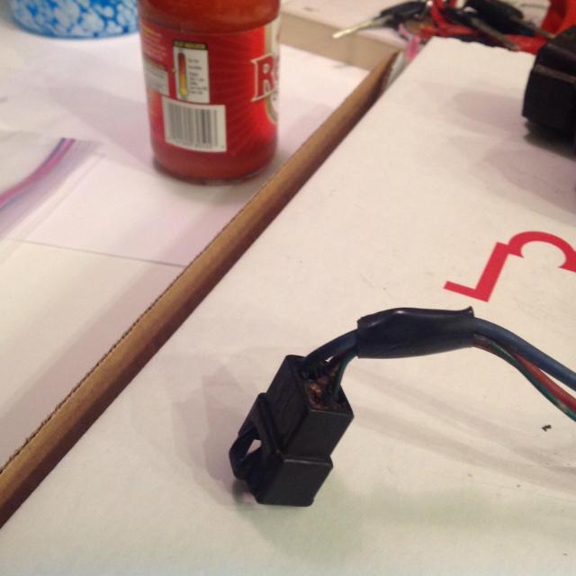
So I got everything back together yesterday and noticed something. The fan is not kicking on at 207ish temp. Though, now, at 220 the fan kicks on medium speed. So, I know the new ECU switch is working perfectly. But I was stumped about the thermoswitch.....I fixed the harness correctly and put in the new sensor. So, I got a piece of wire and tapped into where I fixed the harness. Then Grounded the wire with ignition on. The relay made a clicking noise each time, but no low speed fan. But here is the weird thing, according to the cooling guide, the #3 relay should be the thermoswitch relay. But the relay that was clicking, was #2(which should be parallel with #4 as ECU relays). So I started testing the wiring and noticed something odd. The harness that connects to the relays is about 8 inches long, then has another set of connectors. Like this.

So I pulled out my multimeter and started testing things with ignition on. All three have 2 big wires and 2 small wires going into the connector, then 3 wires coming out of the other side going to the relays. On 2 of the connectors, One big wire has power and one does not. Except for the big wire for the thermoswitch connector. It has no power, no matter what I do. According to the wiring diagram, all relays should have a power source. Does this sound like my issue? Or am I on a goose chase? I don't really care where the relay is located, I just want my switch to work. Like I said, I am not the best with wiring diagrams, so I could be totally wrong. Can someone take a picture of these connectors for me(noting the colors of the big wires on each side of the connector) from their car? Just follow the harness down to the headlight motor area. They are right there. I would be ever so thankful.
PS: I fooled around and switched these 3 connectors around. I got 2 results different than the no thermoswitch but fans kicking on at 220�
One Combination = medium fan speed at 195� down to 188
The other Combination = medium fan speed at all times....lol
No need remove the jiggle-pin on the t-stat. And once you sort out the fan issue and can turn your attention to more simple things, consider PM'ing a member named DaleClark for a set of his Viton check-valves...or get them from his Ebay listing here: http://www.ebay.com/itm/NEW-93-95-RX-7-Viton-Check-Valves-set-of-4-FD3S-/291279658736?pt=Motors_Car_Truck_Parts_Accessories&hash=item43d19edef0&vxp=mtrThey're a much better alternative...barbed ends, stronger body and Viton diaphragm that holds up better to the underhood heat.
Thread Starter
Now,Hit it with a hammer!
iTrader: (1)
Joined: Jul 2014
Posts: 46
Likes: 0
From: Boulder, Colorado
No need remove the jiggle-pin on the t-stat. And once you sort out the fan issue and can turn your attention to more simple things, consider PM'ing a member named DaleClark for a set of his Viton check-valves...or get them from his Ebay listing here: New 93 95 RX 7 Viton Check Valves Set of 4 FD3S | eBay
They're a much better alternative...barbed ends, stronger body and Viton diaphragm that holds up better to the underhood heat.
They're a much better alternative...barbed ends, stronger body and Viton diaphragm that holds up better to the underhood heat.
The valves are en route. Found some that seem identicle to dales for 10$ instead of 20$. Viton valves with kynar bodies. Same specs.
I know it is just 20$ For Dales but 10$ saved, is 10$ earned.
Thread Starter
Now,Hit it with a hammer!
iTrader: (1)
Joined: Jul 2014
Posts: 46
Likes: 0
From: Boulder, Colorado
So after studying the wiring diagrams, seems that on the third relay, one big wire is a ground and the other big wire is coming from the fan motors to be "grounded." And the relay is there to make it complete the circuit and run the fans, when the thermo switch hits a certain temp and grounds.
Also, I guess the short wiring harness had been mixed up at one time, according to the wiring diagram, due to the 3rd relay being in the spot of the 2nd relay. I'm gonna go re look at everything now. I found a diagram with wire colors and will make sure everything matches up.
Ps: the engine has been replaced at a dealer, so who knows......maybe ole "Jimmy Bob" got the wiring switched up when putting things back together........lol
Thread Starter
Now,Hit it with a hammer!
iTrader: (1)
Joined: Jul 2014
Posts: 46
Likes: 0
From: Boulder, Colorado
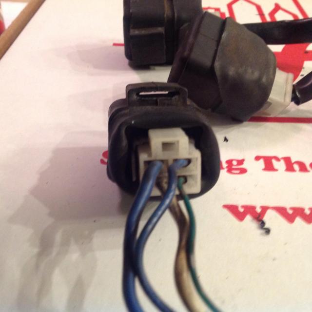
So, I was looking at the wiring diagram/on the car and noticed that 4 wires come from the main harness into the connectors, shown below, and three wires come out to make up the relay harness. But, At each relay I noticed they had 4 wires connecting into the relay clips. So I removed the harness, with relays and took a look. On the wiring diagram, the wire that goes into the connector, that is missing on the other side of the connector, is the (Black Yellow) wires. The diagram says it comes from the 15 Amp Fuse ~ Meter(which is under the dash and controls the dash functions, etc. , if correct).
Main harness connect relay harness
3 wires coming from the connector ment for 4
Relay harness connected to relay with 4 wires
When I opened the harness up, I found that they spliced, in the place of the black/yellow wire, a wire from the large power wires going to the other relays. I am unsure if this is factory, but seems odd. Why would they run the black wire all the way there, if they could have just tapped into this wire in the first place. Seems odd to me.
Harness being spliced, to create wire in place of black/yellow wire for relay 4.
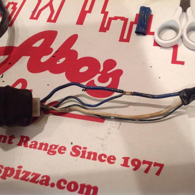
Relay 2 and 3 get the black/yellow power from splicing into relay 2's fan power.
My guess, there is an issue with a ground coming / leaving the number 3 relay, if this wiring above is correct. My question is, when the thermoswitch hits the specified temp of roughly 97C/ 207F, grounding, making the relay click on and grounding the fans, how do the fans get power if the other relays kick on at higher temps/with accessories on? Do the fans have a constant power supply? The wiring diagram, to me, shows that relay 1-2-4 supply the fans power. Am I wrong?
Main harness connect relay harness

3 wires coming from the connector ment for 4

Relay harness connected to relay with 4 wires

When I opened the harness up, I found that they spliced, in the place of the black/yellow wire, a wire from the large power wires going to the other relays. I am unsure if this is factory, but seems odd. Why would they run the black wire all the way there, if they could have just tapped into this wire in the first place. Seems odd to me.
Harness being spliced, to create wire in place of black/yellow wire for relay 4.

Relay 2 and 3 get the black/yellow power from splicing into relay 2's fan power.

My guess, there is an issue with a ground coming / leaving the number 3 relay, if this wiring above is correct. My question is, when the thermoswitch hits the specified temp of roughly 97C/ 207F, grounding, making the relay click on and grounding the fans, how do the fans get power if the other relays kick on at higher temps/with accessories on? Do the fans have a constant power supply? The wiring diagram, to me, shows that relay 1-2-4 supply the fans power. Am I wrong?

I believe the little extension harness you've found is part of a recall campaign. It allows a controller box near the ECU to keep the fans running after engine shutdown for a certain period of time.
Thread Starter
Now,Hit it with a hammer!
iTrader: (1)
Joined: Jul 2014
Posts: 46
Likes: 0
From: Boulder, Colorado