Anybody actually tried the xspower (ssautochrome) ebay intercooler?

 04-20-06, 12:47 AM
#503
Senior Member
Join Date: Oct 2002
Location: Hampton, VA
Posts: 596
Likes: 0
Received 0 Likes
on
0 Posts
I bought an Ebay intercooler similar to the xspower.
It's advertized as 12 x 18 x 3, similar to Pettit CoolchargeIII and ASP/M2 large. The other intercooler in the pic is a small isuzu NPR intercooler, which is 7x14x2. inlet/outlet are only 2.5, but that can be remedied if need be. My battery has been in the trunk for some time now, so it won't be a problem. As far as a duct goes, I got that covered too.


It's advertized as 12 x 18 x 3, similar to Pettit CoolchargeIII and ASP/M2 large. The other intercooler in the pic is a small isuzu NPR intercooler, which is 7x14x2. inlet/outlet are only 2.5, but that can be remedied if need be. My battery has been in the trunk for some time now, so it won't be a problem. As far as a duct goes, I got that covered too.
04-21-06, 02:14 AM
#504
Oh my god, The insides of the pipes are filthy. I spent an hour cleaning them. basically duct tape some steel wool to a 1/2 socket extension and hooked it up to an impact wrench. now the inside of the pipe no longer feels rough. It was filthy before I did this. I ran my fingers over it and my finger came out dirty. Anyone who has this kit should do this if you are at alll concerned about engine life.
No way am I paying that much for a block off plate. I'm going to make one since I have a good cutting tool and some scrap metal lying around.
No way am I paying that much for a block off plate. I'm going to make one since I have a good cutting tool and some scrap metal lying around.
05-07-06, 08:12 AM
#508
Ugh, so there's really no cold-air solution available for use with this intercooler huh? I've noticed there could be room if the whole mess were moved over towards the battery a few more inches, but the piping it comes with is prohibitive because of the angle of the factory intake manifold elbow. How much does the HKS elbow reduce this bend away from the battery?
I wasn't happy at all with the piping the kit came with so I fabbed up my own piping using the 90* bend hard pipe from the factory setup at the turbo outlet. This way you don't have to wrench the poor couplers at funky angles to get it to fit, but the clearance with the hood is really tight because of the bend. I'll take some pics later.
Any recommendations on intake solutions or ways to move the whole intercooler mess towards the battery would be greatly appreciated. Not the most elegant of installs but heck for $125 for the complete kit it's worth just trying to see even thought I made my own pipes. TIA!
05-07-06, 11:49 AM
#509
Couple pics of how I've got it set up:
I need a real intake solution, this garbage I threw in pains me to think about. The turbo outlet pipe is a cut-down Volvo turbo pipe ($2 at your local junkyard).
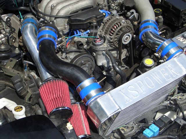
I reused the 90* coupler from the stock intercooler setup. The inner diameter matches that of the turbo outlet so no worries, though the bend radius is a little too large so hood clearance is almost an issue.
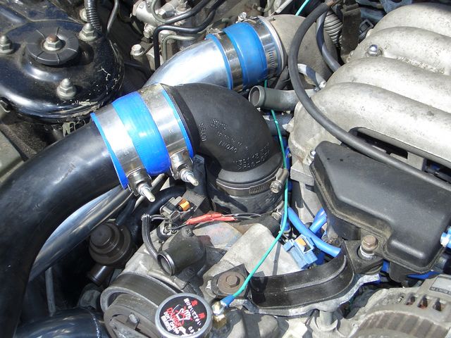
I'd like to ultimately shift the whole IC closer to the battery but I'll have to come up with a better piping solution for the I/C outlet -> tbody elbow or get my hands on one of those HKS dealies.
I need a real intake solution, this garbage I threw in pains me to think about. The turbo outlet pipe is a cut-down Volvo turbo pipe ($2 at your local junkyard).
I reused the 90* coupler from the stock intercooler setup. The inner diameter matches that of the turbo outlet so no worries, though the bend radius is a little too large so hood clearance is almost an issue.
I'd like to ultimately shift the whole IC closer to the battery but I'll have to come up with a better piping solution for the I/C outlet -> tbody elbow or get my hands on one of those HKS dealies.
05-07-06, 12:30 PM
#511
Senior Member
Thread Starter
Join Date: Aug 2002
Location: DC
Posts: 587
Likes: 0
Received 0 Likes
on
0 Posts
Originally Posted by HDP
Air will only flow through the IC core so fast, so with the inlet being larger, more air will enter the duct at higher speeds but if it has nowhere to go, it has no choice but to "overflow". Think of it as a cup with a hole in it, if you begin to pour water in the cup, it will drain out of the hole, but if you begin to pour faster than the hole can drain, eventually the water will rise to the rim and overflow. So keeping the inlet smaller will limit the amount of air entering the duct and allow the air to flow through the core and not spill out.
05-07-06, 12:35 PM
#512
Originally Posted by jayk
If this were true, why don't fmic's overflow with all the additional air from having it up front in the nose?
EDIT: air is invisible so I guess it does vanish... but you know what I mean.
05-07-06, 12:50 PM
#513
Senior Member
Thread Starter
Join Date: Aug 2002
Location: DC
Posts: 587
Likes: 0
Received 0 Likes
on
0 Posts
Originally Posted by HDP
Umm, they do. Why do you think some cars with FMIC have problems with cooling. All the air that hits the intercooler isn't getting to the radiator. The air doesn't vanish, so it has to go somewhere.
EDIT: air is invisible so I guess it does vanish... but you know what I mean.
EDIT: air is invisible so I guess it does vanish... but you know what I mean.
Not to turn this into a discussion about fmic's, but it seems to me that you must be able to increase airflow at least a little to a smic or else fmic's wouldn't have any benefit.
05-07-06, 01:00 PM
#514
Originally Posted by jayk
I thought it was because the air passed through the ic and picked up heat while also slowing down, so the radiator didn't get good clean air.
Not to turn this into a discussion about fmic's, but it seems to me that you must be able to increase airflow at least a little to a smic or else fmic's wouldn't have any benefit.
Not to turn this into a discussion about fmic's, but it seems to me that you must be able to increase airflow at least a little to a smic or else fmic's wouldn't have any benefit.
05-07-06, 01:15 PM
#515
Senior Member
Thread Starter
Join Date: Aug 2002
Location: DC
Posts: 587
Likes: 0
Received 0 Likes
on
0 Posts
Originally Posted by HDP
Let me see if I can explain this again in a different way... air will only flow through (pass into) the IC core at a certain speed, so you limit the size of the IC duct inlet to allow only that amount of air to flow in at a given time (inlet size will vary according to how much air will pass through the IC core at a certain speed). If you allow more air into the IC duct than is able to flow through the IC core, it's not going to sit and wait to flow through the core, it's going to find the path of least resistance, which is back out the way it came in (overflow). Do you follow what I'm saying?
05-07-06, 01:29 PM
#516

As much as it pains me to say HDP is actually right on this account. A kitchen analogy might help to explain what's happening. Imagine tipping a bottle of thick syrup to an angle so that it pours at a continuous rate. Pour the syrup into a small collander (strainer) that restricts a lot of the syrup passing through it. In the real world you tip the syrup bottle up to slow the pour rate down as the syrup fills the strainer and threatens to spill out of the top. Imagine that you cannot lift the bottle and it pours at the fixed rate, soon enough the syrup is rapidly spilling over the strainer on all sides eventhough some is still passing through the strainer.
We could get carried away with this and mention that as the syrup piles up it will cause more syrup to pass through the strainer, essentially giving it a gravitational push, just as air at speed will "push" or compress the air trapped in the mouth of the car going through the IC. This doesn't change the syrup spilling over, just like the air but does mean that the syrup/air passing through is a gradient.
Imagine your car standing on end and the FMIC as a strainer and pour the air on in. After a certain speed the air will "spill" out of the front mouth of the car. The further forward the FMIC is mounted the worse this effect will be. The worst offenders are those that mount flush with the opening at the very front.
05-07-06, 01:29 PM
#517
Originally Posted by jayk
Yes. But how do you know that balance has been reached with a medium sized ic fed from a stock ic sized duct? If you were to move a medium sized smic and put it up front of the radiator receiving all the incoming air would it perform the same, worse, or better?
05-07-06, 01:30 PM
#518
Originally Posted by HDP
Let me see if I can explain this again in a different way... air will only flow through (pass into) the IC core at a certain speed, so you limit the size of the IC duct inlet to allow only that amount of air to flow in at a given time (inlet size will vary according to how much air will pass through the IC core at a certain speed). If you allow more air into the IC duct than is able to flow through the IC core, it's not going to sit and wait to flow through the core, it's going to find the path of least resistance, which is back out the way it came in (overflow). Do you follow what I'm saying?
If restricting the air flow in front of heat exchangers made them more efficient, then the oil cooler and the radiator would have little ducts in front of them too. The RX7 SMIC has a duct because it is the least important of the three exchangers (since the other two deal with cooling the engine), other design constraints (primarily aesthetics, I suspect) don't allow enough frontal area to supply the SMIC with full frontal flow, and the stock IC was tiny anyway - so they jammed it behind the radiator and fed it with a duct. The duct is not there to make the IC work better. It is there because of other design constraints.
Jayk, you are exactly right - the FMIC does a great job cooling the intake charge, but its placement in front of the radiator means the radiator gets less, and hotter, air. And obviously, placing a duct in front of an FMIC would make the IC (and the radiator) perform less efficiently, not more.
The vmount appears to be the highest performance solution to this problem. Other modifications I can imagine to increase air into an SMIC are increasing the duct size by creating a path for air OVER the radiator (someone on this forum did that to fit a 99 spec air intake, and the idea could be adopted to feed an SMIC). Another would be a scooped hood and associated ducting (but that would be ugly). I am sure there are plenty of ways I haven't thought of - anyone making their own duct should give it some thought.
05-07-06, 01:58 PM
#519
Lives on the Forum
Join Date: Dec 2001
Location: San Lorenzo, California
Posts: 14,716
Likes: 0
Received 8 Likes
on
8 Posts
Originally Posted by primerGrey
If restricting the air flow in front of heat exchangers made them more efficient, then the oil cooler and the radiator would have little ducts in front of them too.
Ducting serves to both smooth out the airflow and to slow it down before it enters the cooler. This is seen with both the stock car, as well as with the coolers on almost any race car made.
05-07-06, 02:47 PM
#520
Originally Posted by rynberg
They do!
Ducting serves to both smooth out the airflow and to slow it down before it enters the cooler. This is seen with both the stock car, as well as with the coolers on almost any race car made.
Ducting serves to both smooth out the airflow and to slow it down before it enters the cooler. This is seen with both the stock car, as well as with the coolers on almost any race car made.
Fair enough, but lets be clear about what we mean by ducting. Ducting that doesn't reduce cross sectional area just traps the air and helps increase the stagnation pressure in front of the exchanger, improving the exchanger efficiency. This is clearly of benefit, because it increases the pressure gradient through the exchanger, increasing the mass flow of air through the exchanger.
Ducting that reduces the cross-sectional area is there to optimize some performance parameter other than IC efficiency - on race cars, I could imagine using a smaller cross-section duct because it is of greater benefit to reduce total air friction (which goes up as a square of velocity) than maximize IC cooling efficiency.
05-07-06, 08:26 PM
#521
Senior Member
Thread Starter
Join Date: Aug 2002
Location: DC
Posts: 587
Likes: 0
Received 0 Likes
on
0 Posts
Originally Posted by HDP
I never said I knew the balance, I only stated what would happen if the duct inlet was made too large. There would be too many variables to enter to determine what the balance of a setup would be. Maximum speed of vehicle, CFM of airflow through the IC core, volume of IC duct, size of duct opening to allow only the volume of air to enter that the duct will hold at given speeds... just to name a few.
05-07-06, 09:11 PM
#522
Originally Posted by jayk
1...wouldn't increasing the size of the strainer allow you to dump more syrup into the container? 2...if we are talking about replacing the stock ic with an ic that has approximately 4 times the frontal area, can't the bigger ic pass through more air? 3. but given a bigger ic doesn't it make sense to have a bigger duct to feed it more air?
2. Yes.
3. Yes
05-08-06, 07:54 AM
#523
Racing Rotary Since 1983
iTrader: (6)
i just happened to see kevin wyum's name on a post in this huge thread so thought i'd drop by.
last summer i did some airspeed thru the intercooler work.
i have approx 80 louvers in my hood, hoping to promote air flow THRU the heat exchangers. you can have all the frontal exposure but if you have a high pressure area behind the core you hit a brick wall as to flow. the louvers promote flow, that was my theory.
i windsurf and just happen to have a digital windspeed gauge, i think it's called a manometer. i rigged it behind my ASP Large (M2 1999 or 2000 vintage).
w the louvers at 60 mph any guess's as to flow exit speed thru the core?
6 mph.
without the louvers 4.5 mph.
60 mph following a car 3 mph.
howard coleman
05-08-06, 11:04 AM
#524
2/4 wheel cornering fiend
Howard,
Unless all those louvers you put in your hood are sealed off directly to the IC, all you're doing is promoting airflow through the engine bay (which isn't necessarily a bad thing).
The multiple fins and thickness of an IC core provide a substantial obstacle to airflow, and the only way to suppress stagnation and promote flow through that area is to create a just as substantial negative air pressure area directly behind the core. This is why the ducting should be just as elaborate behind the heat exchanger as it is in front of it.
05-08-06, 11:18 AM
#525
Originally Posted by Kento
The multiple fins and thickness of an IC core provide a substantial obstacle to airflow, and the only way to suppress stagnation and promote flow through that area is to create a just as substantial negative air pressure area directly behind the core.
Dave