
Alternative/Replacement for Boost Control Solenoid


I wasn't understanding your earlier post. I thought you were going to hook both Port #1 and Port #3 to boost, which would be pointless, but that routing is correct.
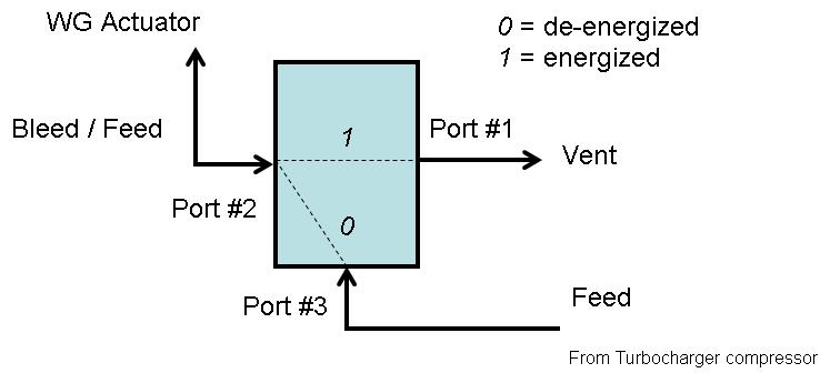
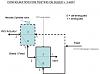
Note that this 3 port solenoid functions exactly like a 5 pin relay:
85 and 86 pins are for the coil, just like in the solenoid valve
pin 30 is COM
pin 87a is NC... but in an electrical circuit, the terminology is reversed so "closed" means continuity in the circuit
pin 87 is NO... but in an electrical circuit, the terminology is reversed so "open" means no continuity'
compare to your diagram, noting that the solenoid coil is not depicted
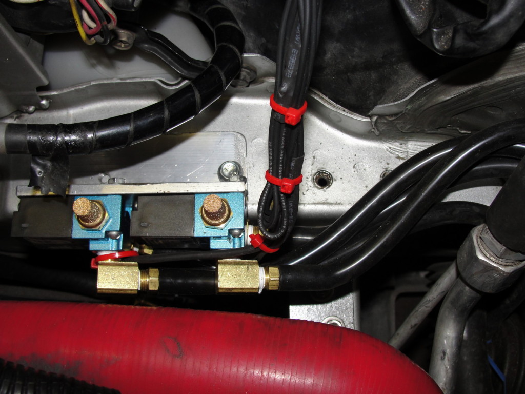
One more picture. I connected the AMP connector sample to the harness. It fits perfectly.
I have a question - unrelated. As I was taking thee picture above, I noticed one of the metal tubes is connected to nothing. Is it perhaps a vent from one of the other solenoid valves?
Thanks.
I have a question - unrelated. As I was taking thee picture above, I noticed one of the metal tubes is connected to nothing. Is it perhaps a vent from one of the other solenoid valves?
Thanks.

Can't wait to see the outcome, as I have a FJO boost controller (see attached) that I'd like to setup on my stock twins still running sequentially.
:-) neil
His last message last Friday
--------------
Sandro,
You will probably get yours first based on the locations. You will want to check for terminal alignment and that the seal is being properly utilized as this was a questionable issue for this connector application based on the mold on the parts themselves.
James Ballenger
----------------
He is referring to the sample I got from Tyco. I then kept in the loop by sharing my findings over the weekend - that these are indeed the right connectors and sent copy of the pics. But he has not replied yet.
Great news! BMostorsport will be stocking the AMP connectors, both male and female.
see email below
- Sandro
---------------------------
Sandro,
Looks good. We can make pigtails and should have both the male and female sides in stock in a few more days here. We have the terminals and seals already and will be getting the housings and lock plates shortly.
The descriptions might change a little but the pigtail part numbers are below. They should be added to the website in a few days:
CONN-85729 2 - Way Boost Control Solenoid Plug Pigtail, Black
CONN-85730 2 - Way Boost Control Solenoid Receptacle Pigtail, Black
Regards,
James Ballenger
----------------------------
well that pretty much makes the Apex'i boost control kit an even more expensive and almost worthless product, even for non sequential owners
I would really like to see how your boost control tuning changes from switching both precontrol and wastegate to these inexpensive 3 port units
I would really like to see how your boost control tuning changes from switching both precontrol and wastegate to these inexpensive 3 port units
We'll see it...
I was thinking of ways of making easy back to back comparisons/logs between the OE/PFC boost control based on 2-way bleed valves and these 3-way MAC valves.
I got a small 3-port manual valve today (Humphrey TAC) and was thinking on plumbing the tubes like this

The dotted line indicates the OE feed.
The manual valve is toggle operated. At first I thought I could use the second MAC valve for that but I did not like the idea of keeping the solenoid continually energized.
I am also thinking of installing an electrical switch to send the PFC signal either to the OE bleed valve or to the MAC valve. I will make short extensions using the AMP connectors and make the switch easily accessible. This way, I won't have to remove IC cross pipe and pressure tank to access connect/disconnect the OE solenoids.
The MAC and the manual valve could be located somewhere near the WG feed line an still use relatively short tubes.
Any comments or suggestions?
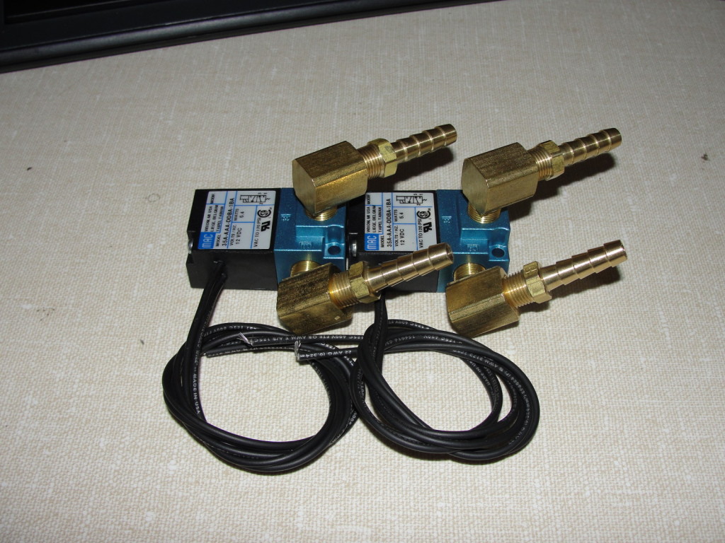
By the way, the MAC valve impedance is like 27-28 ohm. I forgot to measure the OE solenoids impedance when I took pictures last weekend. I remember reading that the the OE solenoid impedance should be around 30 ohm. If that is the case, the 2-3 ohm difference should not be a problem for the PFC, I guess. No need to add resistors, right?
Once done with the post transition, if it works, I will then look at the PC. Right now, this seems to be working quite well as it is - although I guess the WG controlled by the MAC valve may affect the primary, before transition as well.
But I share your view that it would be great if we could make it work with two independently tunable controls, PC and WG separately.
Thanks,
Sandro
I was thinking of ways of making easy back to back comparisons/logs between the OE/PFC boost control based on 2-way bleed valves and these 3-way MAC valves.
I got a small 3-port manual valve today (Humphrey TAC) and was thinking on plumbing the tubes like this
The dotted line indicates the OE feed.
The manual valve is toggle operated. At first I thought I could use the second MAC valve for that but I did not like the idea of keeping the solenoid continually energized.
I am also thinking of installing an electrical switch to send the PFC signal either to the OE bleed valve or to the MAC valve. I will make short extensions using the AMP connectors and make the switch easily accessible. This way, I won't have to remove IC cross pipe and pressure tank to access connect/disconnect the OE solenoids.
The MAC and the manual valve could be located somewhere near the WG feed line an still use relatively short tubes.
Any comments or suggestions?
By the way, the MAC valve impedance is like 27-28 ohm. I forgot to measure the OE solenoids impedance when I took pictures last weekend. I remember reading that the the OE solenoid impedance should be around 30 ohm. If that is the case, the 2-3 ohm difference should not be a problem for the PFC, I guess. No need to add resistors, right?
Once done with the post transition, if it works, I will then look at the PC. Right now, this seems to be working quite well as it is - although I guess the WG controlled by the MAC valve may affect the primary, before transition as well.
But I share your view that it would be great if we could make it work with two independently tunable controls, PC and WG separately.
Thanks,
Sandro
Don't know what happened... I swear I saw the pic in my preview... It may have to do that I keep getting disconnected while typing, then asked to log in again, then i don't know...
I any event...this is the sketch of the plumbing
It does not show the wiring for sending the signals from the PFC. I will use a toggle switch DPDT ON-OFF-ON for that.
The first ON will send the PFC signal to the stock bleed solenoids. In that position, the ports 1-2 of the manual valve shall be aligned (boost feed to the actuator).
Switch OFF and ports 1-2 aligned in the manual valve can be used to further confirm that boost creep is not due to unported WG. Since the bleed valve is NC when de-energized, this is like capping the outlet from the actuator with a switch...
The second ON of the switch will send the PFC signal to the MAC solenoid - while the manual valve shall have now be switched to have the ports 2-3 aligned.
With the MAC solenoid running (through your combination of switches), the bleed line will still be there on the wastegate actuator, but as you said the factory wastegate solenoid will be closed. I wonder if having that extra volume of air to fill will affect response? Also, will you have a switch to direct the PFC duty signal to either the factory 2 way solenoid or the MAC 3 way solenoid?
I mean if it were me I wouldn't go through with that level of complexity because it throws a bunch of extra plumbing & wiring which could require additional troubleshooting. The extra length of hoses could also cause a pressure drop, but I have no idea how much it would be and whether there would be a noticeable difference in the performance to the system. I know that to an extent you are doing this setup just for the hell of it, to see if you can get it to work more than anything. And I understand that.
I mean if it were me I wouldn't go through with that level of complexity because it throws a bunch of extra plumbing & wiring which could require additional troubleshooting. The extra length of hoses could also cause a pressure drop, but I have no idea how much it would be and whether there would be a noticeable difference in the performance to the system. I know that to an extent you are doing this setup just for the hell of it, to see if you can get it to work more than anything. And I understand that.
Thanks for your comments.
The idea was to have a way of comparing the two systems "on the fly" - i.e. taking several logs with various target pressure and duty settings - with no need for redoing the plumbing in between or upon second guessing.
You have a point with the bleed line while using the MAC valve. A way of looking at it is that the bleed line volume will contribute to the overall volume of the WG actuator (since the OE bleed valve will be de-energized and closed). I don't know if such volume is relevant or just a fraction of the WG actuator, but at least qualitatively it certainly will slow down both the fill and the vent of the actuator somehow.
As for the electrical switch, yes I am planning on using a DPDT toggle switch with 6 terminals. 2 of the terminals are the "common" connected to the harness female plug - i.e. the DC pulse signal from the PFC. The other couple of terminals will be connected to the OE 2-way bleed valve solenoid and to the the MAC solenoid.
I am planning on placing the DPDT switch close to the manual pneumatic 3-port valve. This rig could be installed on the passenger side rail, not that far from the WG actuator to minimize the volume of extra piping, but still be easily accessible to flip the two toggles.
And you are right. I am doing all of this just for the hell of it...
But...it's also your fault... your thread on the seq boost control and the Datalogit
- Sandro
OE style connectors now available at Ballanger Motorsports
Ermail received yesterday
-------------------------------------------
Sandro,
We have listed the parts online with the links below:
Connector only:
http://www.bmotorsports.com/shop/pro...oducts_id/1675
http://www.bmotorsports.com/shop/pro...oducts_id/1670
Connector Kit (with loose terminals and seals):
http://www.bmotorsports.com/shop/pro...oducts_id/1671
http://www.bmotorsports.com/shop/pro...oducts_id/1672
Connector Pigtail (pre-assembled with 12" leads):
http://www.bmotorsports.com/shop/pro...oducts_id/1673
http://www.bmotorsports.com/shop/pro...oducts_id/1674
---------------------------------------------
If the tests are successful, can you make a new thread with a simplified writeup for swapping out both precontrol and wastegate solenoids? Explain the setup, list the parts needed, explain the routing diagram, etc.--aimed toward a general audience.
I was also thinking of logging pressure in the actuators. They may provide good information v. the pressure in manifold. I guess I could use a couple of MAP sensors and send the signals to the Datalogit.
I sent a couple of PM. Ttey seem to be selling for $25 or $30 delivered. Does anyone reading this thread have a spare one?
- Sandro
P1 0.95 67 (boost target and initial duty)
S1 0.90 82
P2 1.00 70
S2 0.95 87
Have fun!
- Sandro

If so, where in the FC Edit (screen shot) ?
Thanks,
:-) neil

