
Alarm Buzzer above 2000 RPM, possible Malfunctioning Over Revolution Warning Alarm?


Absolutely it does!
Any and all advice I can get is appreciated!
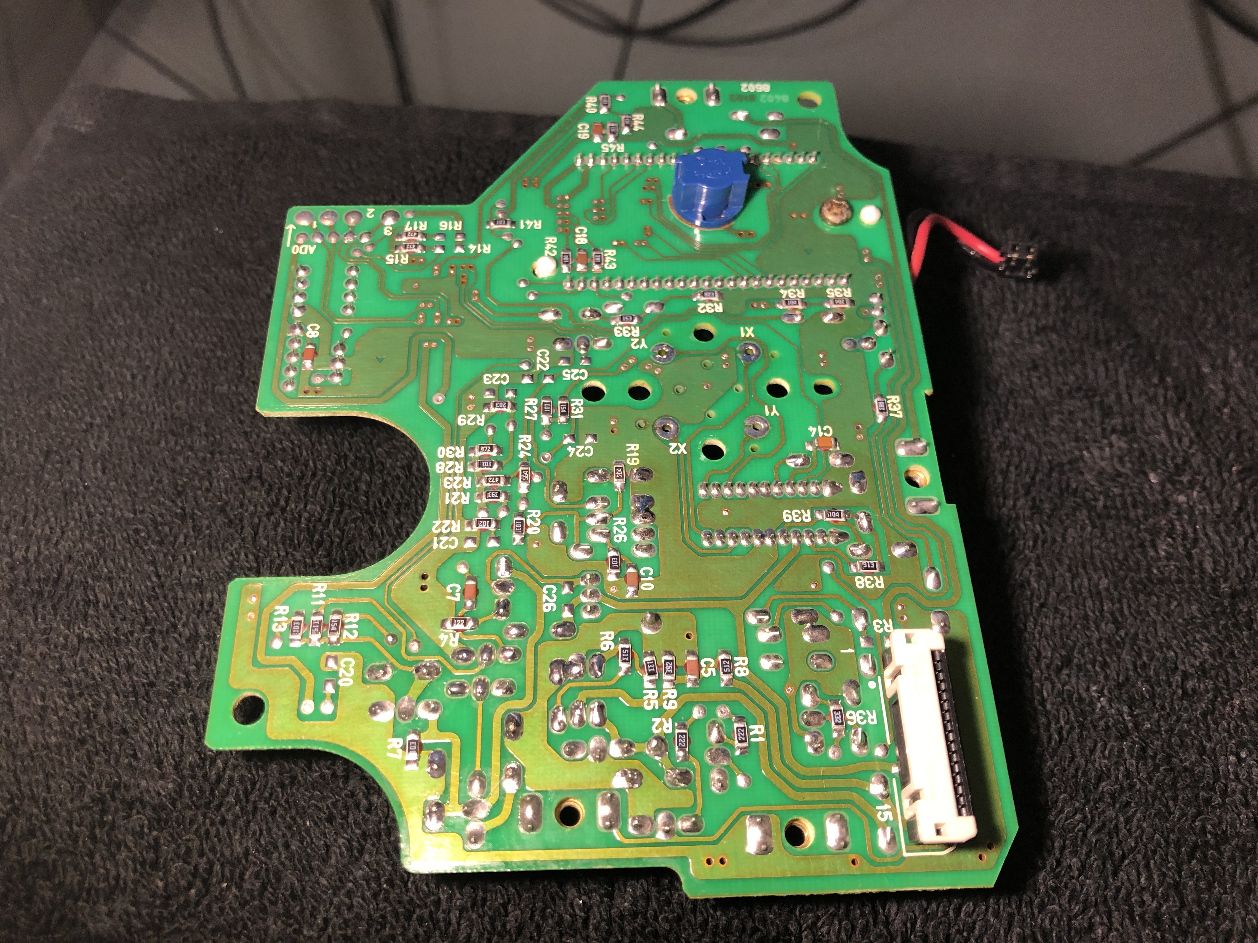
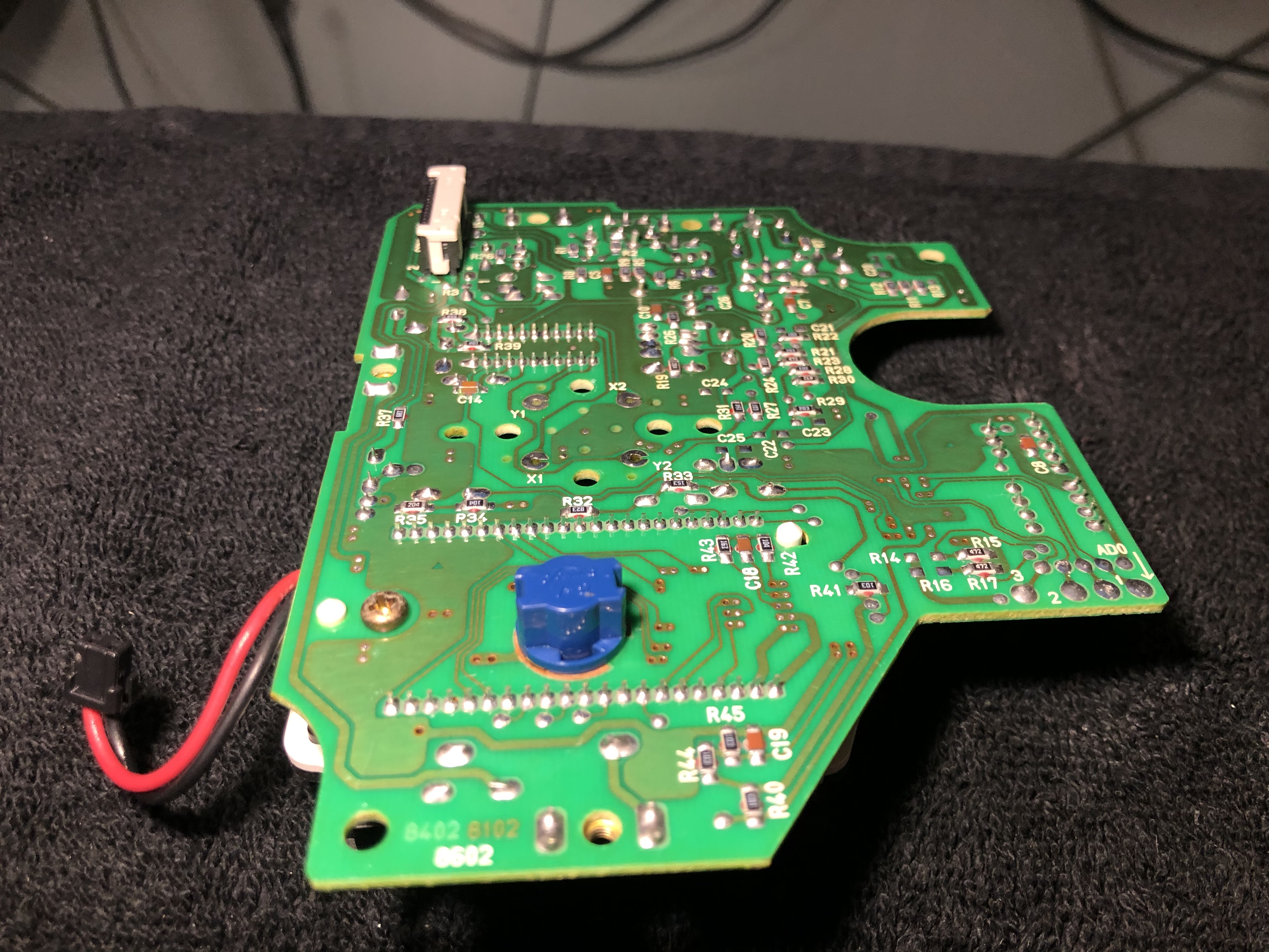
There are several places I can see that are not as good as I had hoped, and might be a consideration to go back over now that I can see it �larger��
If there is anything you feel could use a going back over or touch up please feel free to make note.
I notice several small sharp drags quite a few inclusions, while not the end of the world� I guess I could have done a better job cleaning better it appears� I assume those are left over corrosion and pollutants I didn�t quite manage to get that were hiding in the harder to reach spots?
Any solder ***** or bridges apparent to you, and common places those might occur to specifically look for? Any places that might be good to check continuity or lack thereof?
Any improperly placed or polarized caps that you might be able to catch?
I tried to be meticulous as I am able, and repeat my checks�but that is a known weakness despite trying to make extra accommodations for.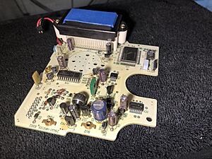


Any and all advice I can get is appreciated!
There are several places I can see that are not as good as I had hoped, and might be a consideration to go back over now that I can see it �larger��
If there is anything you feel could use a going back over or touch up please feel free to make note.
I notice several small sharp drags quite a few inclusions, while not the end of the world� I guess I could have done a better job cleaning better it appears� I assume those are left over corrosion and pollutants I didn�t quite manage to get that were hiding in the harder to reach spots?
Any solder ***** or bridges apparent to you, and common places those might occur to specifically look for? Any places that might be good to check continuity or lack thereof?
Any improperly placed or polarized caps that you might be able to catch?
I tried to be meticulous as I am able, and repeat my checks�but that is a known weakness despite trying to make extra accommodations for.


Should I replace the cap on the Tachometer? Strictly because of age?
And CPU2 for the same reason?
Does anyone happen to know if they make a compatible LED drop in replacement bulbs for the cluster possibly?
And CPU2 for the same reason?
Does anyone happen to know if they make a compatible LED drop in replacement bulbs for the cluster possibly?


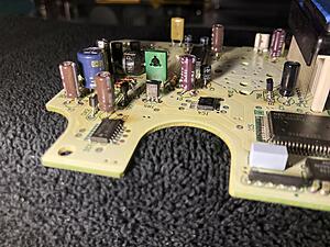
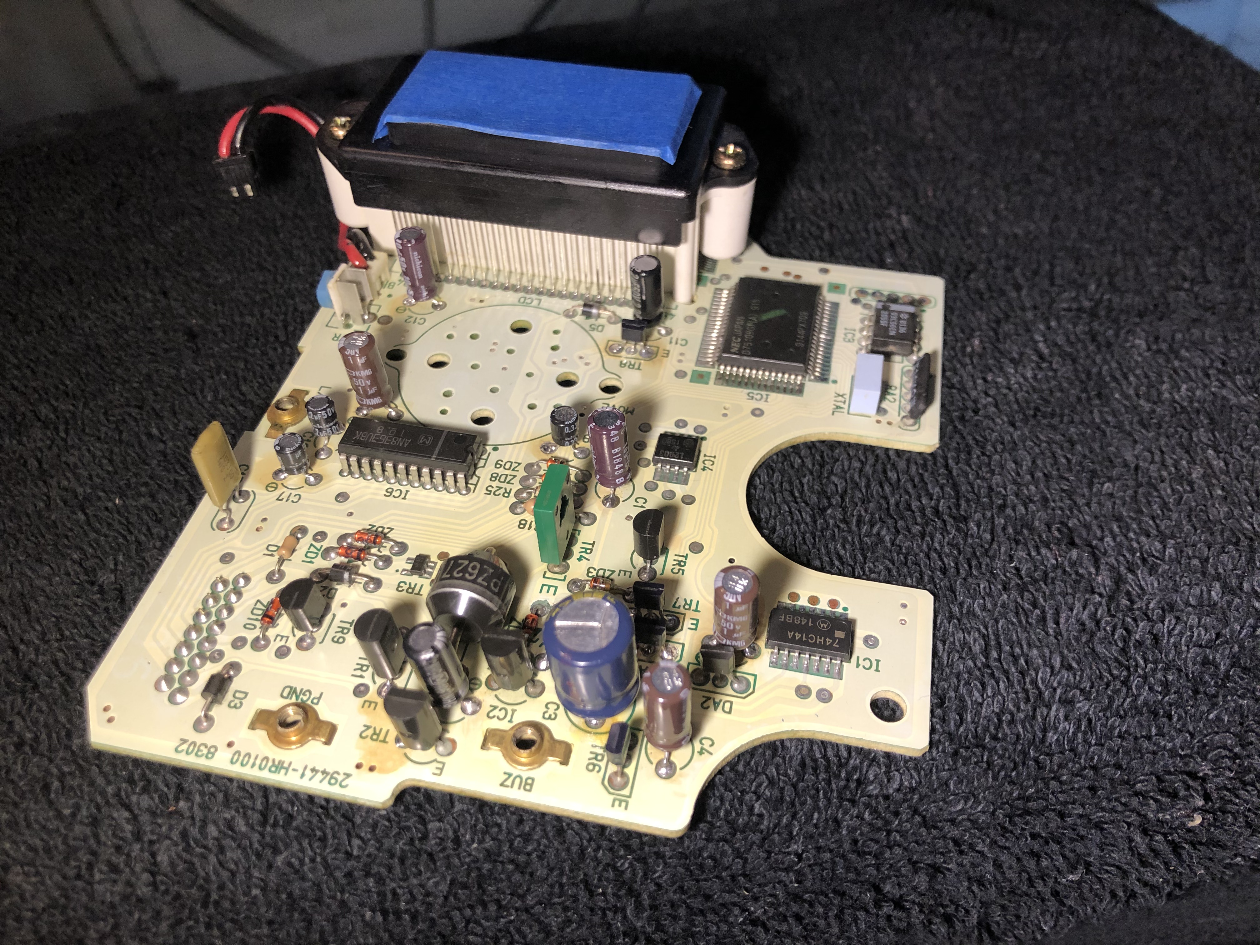
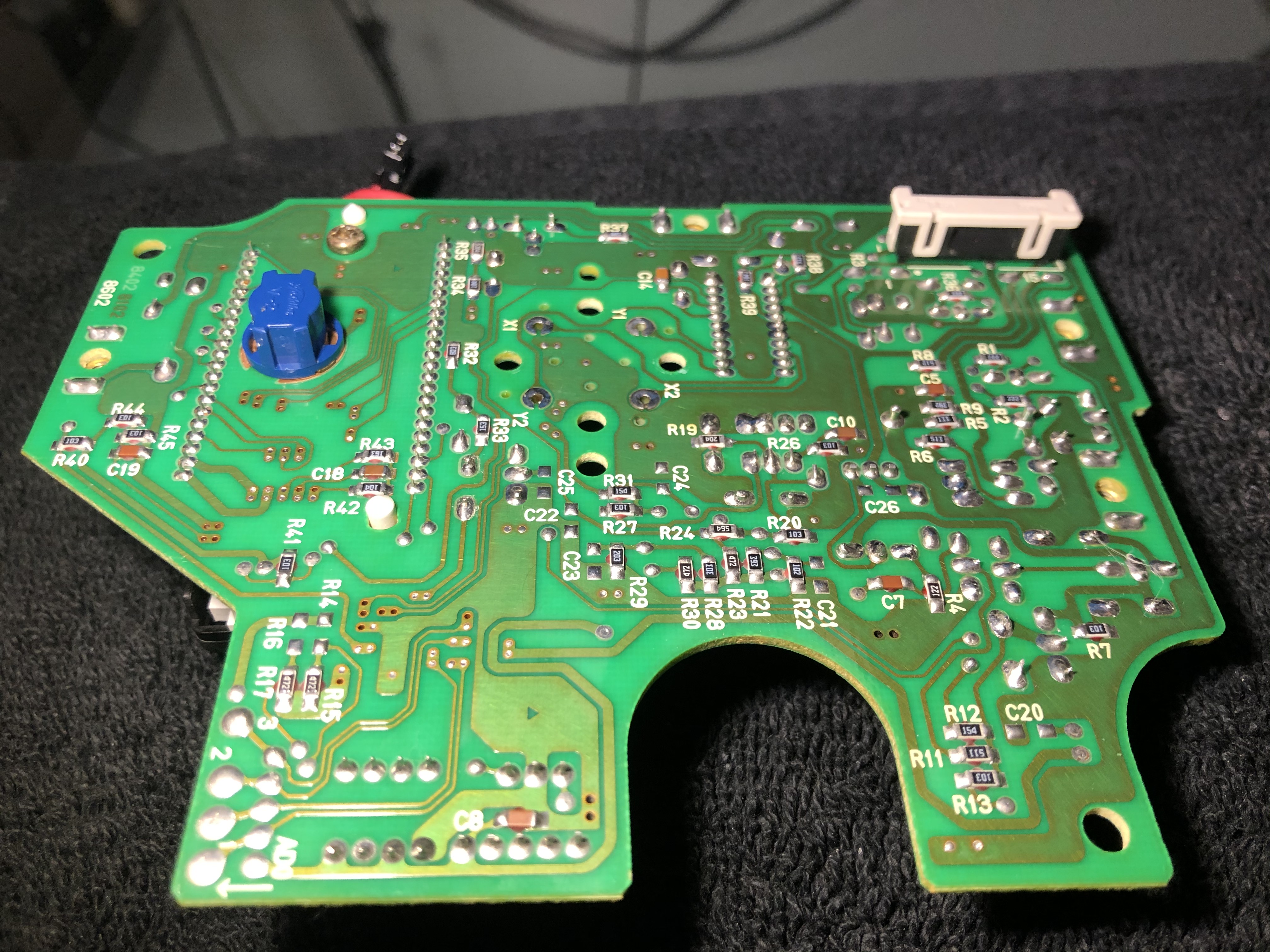
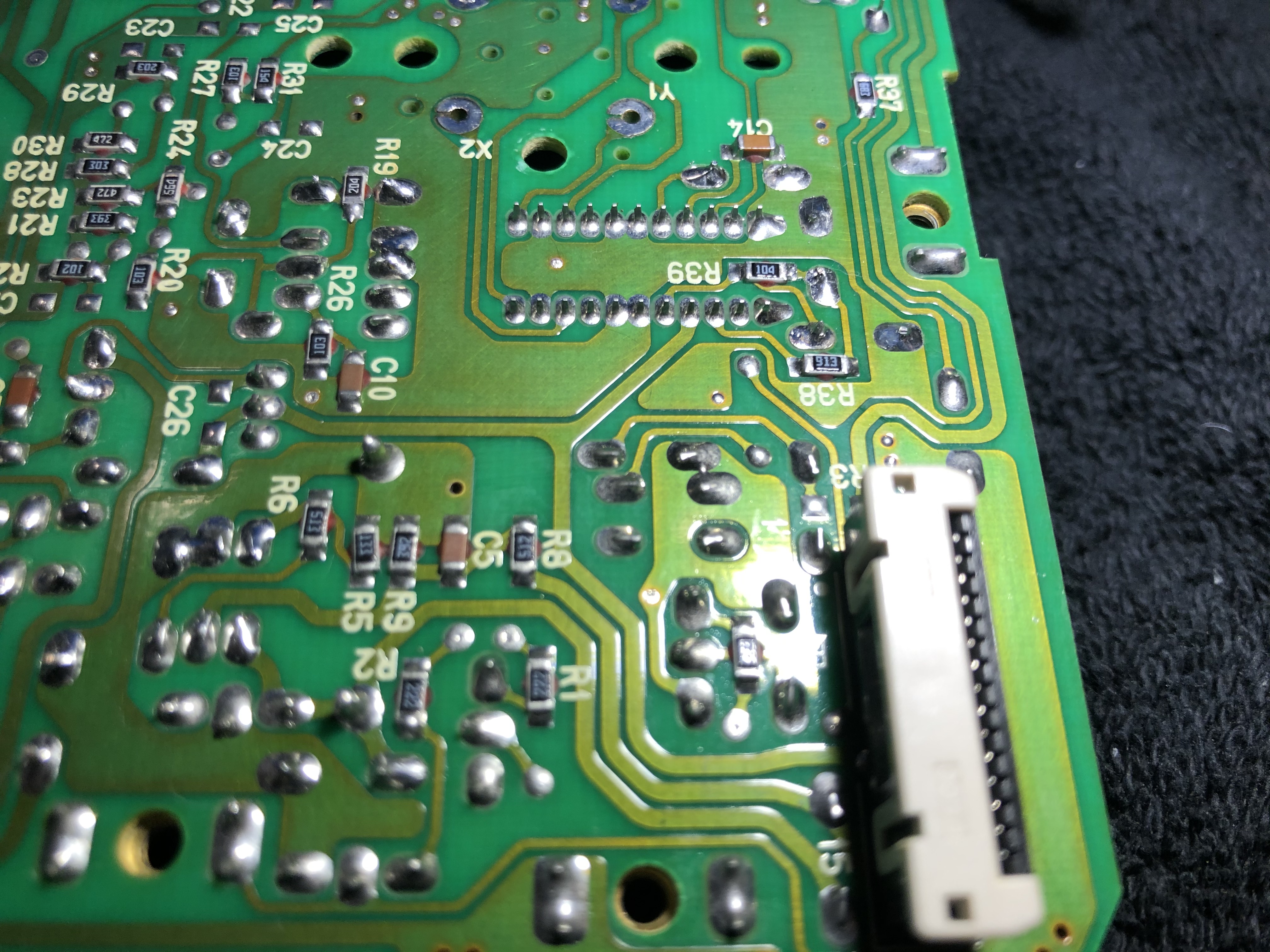
Excellent work on soldering the new capacitors in place! All the polarities look good too. Could you post a couple of photos of C3's solder joints? The photos usually cast a shadow on them.
Stick to getting your speedo board repaired first. So hold off on replacing the caps on the tach and CPU#2. Once we verify everything works then you could replace them.
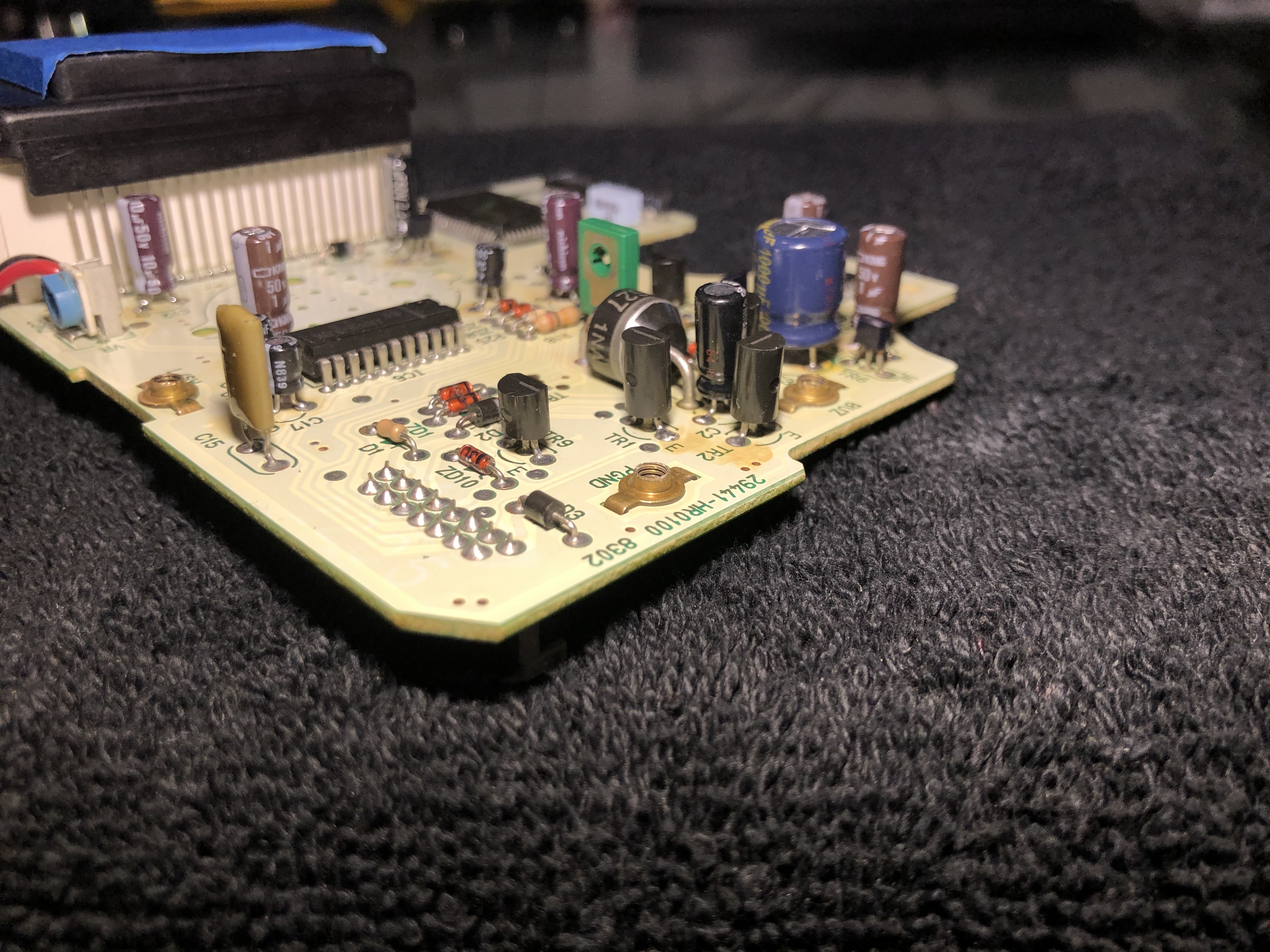
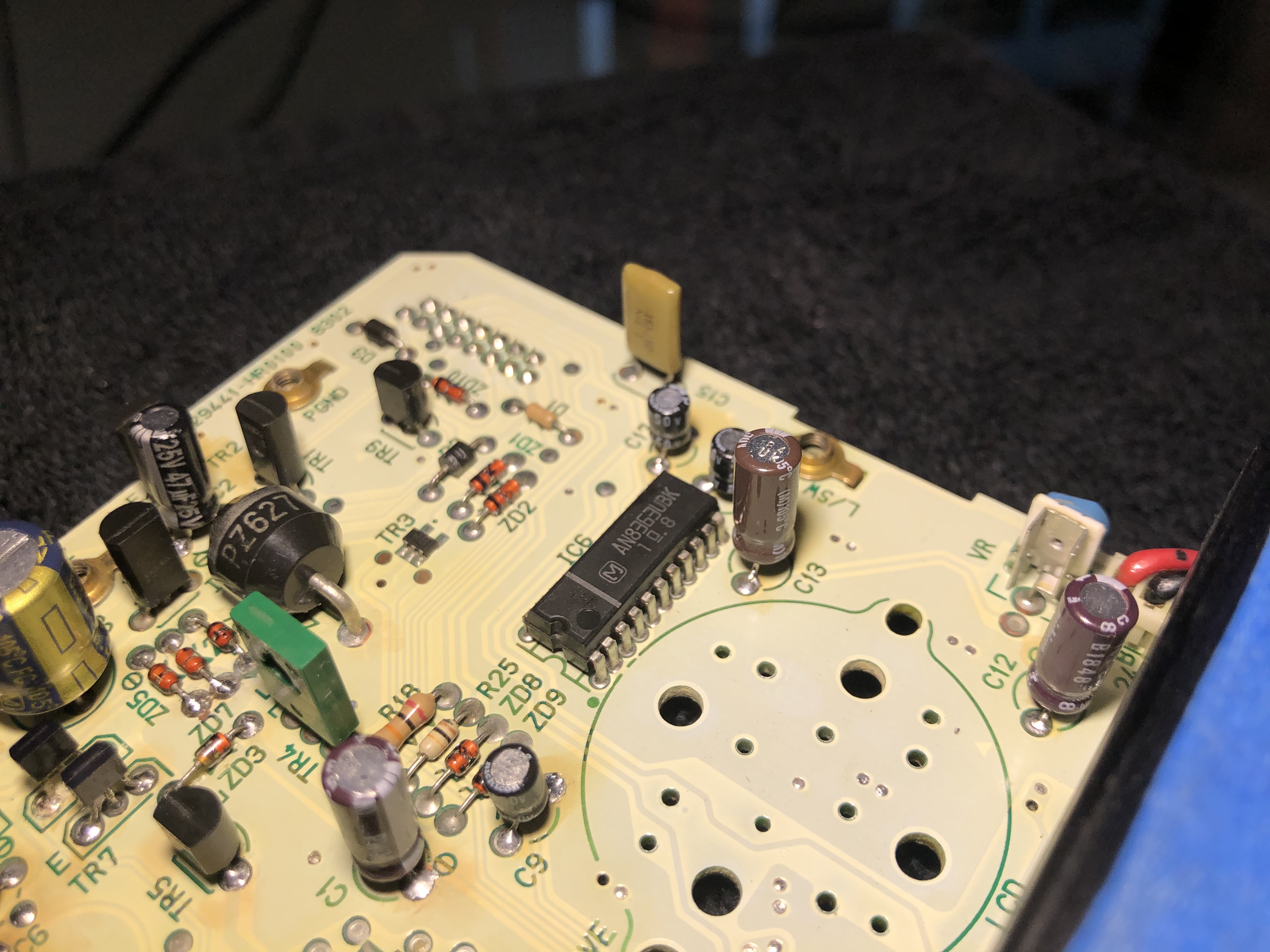
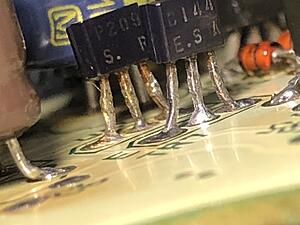
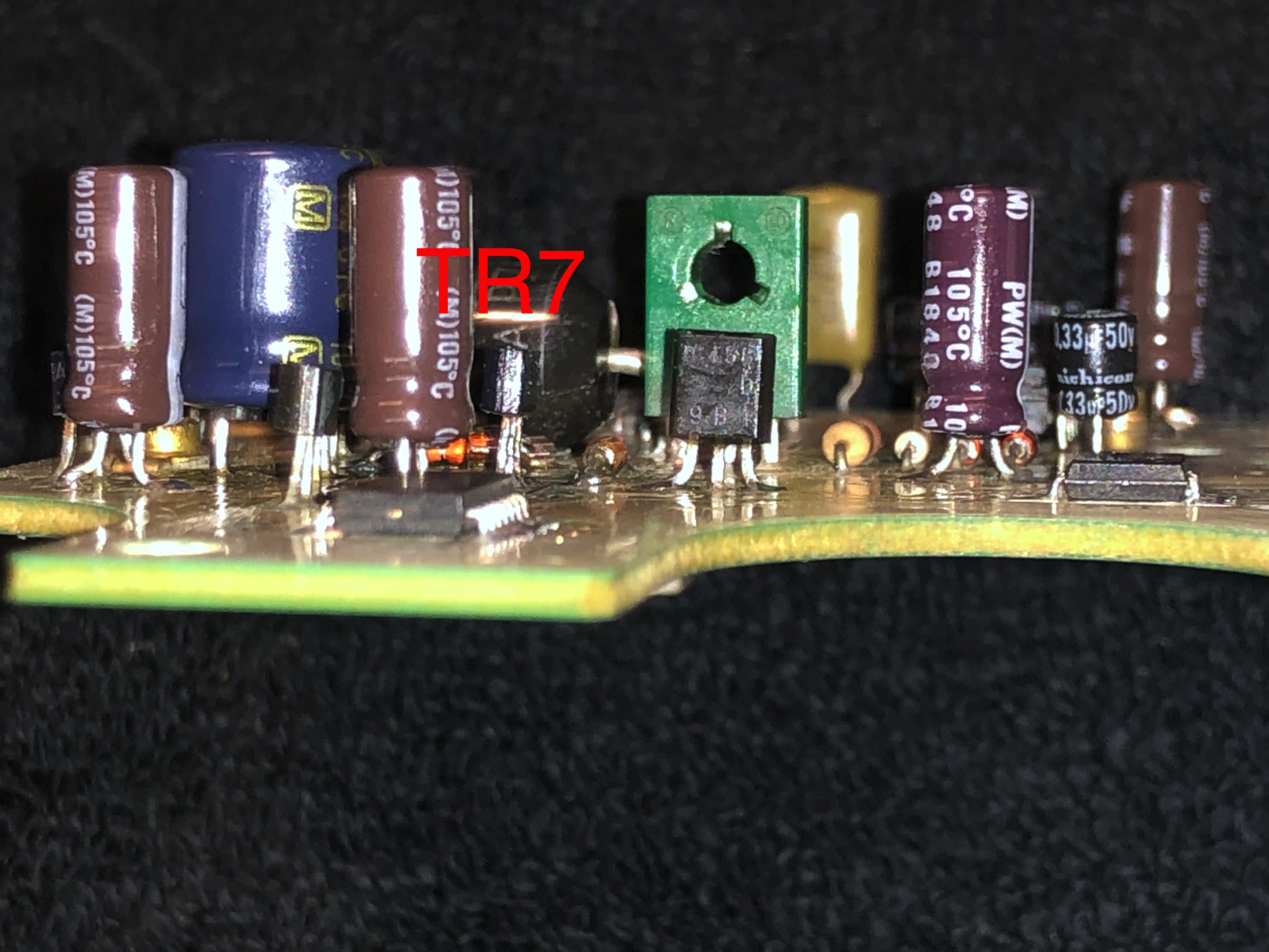
Based upon your photos, take a hard look at TR7. Specifically, its center leg. It looks either broken or a cold joint. You may need to re-solder that leg. Be VERY careful though! You do not want to loose that leg. You could post additional photos of TR7 before doing any additional work to it.
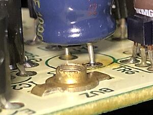
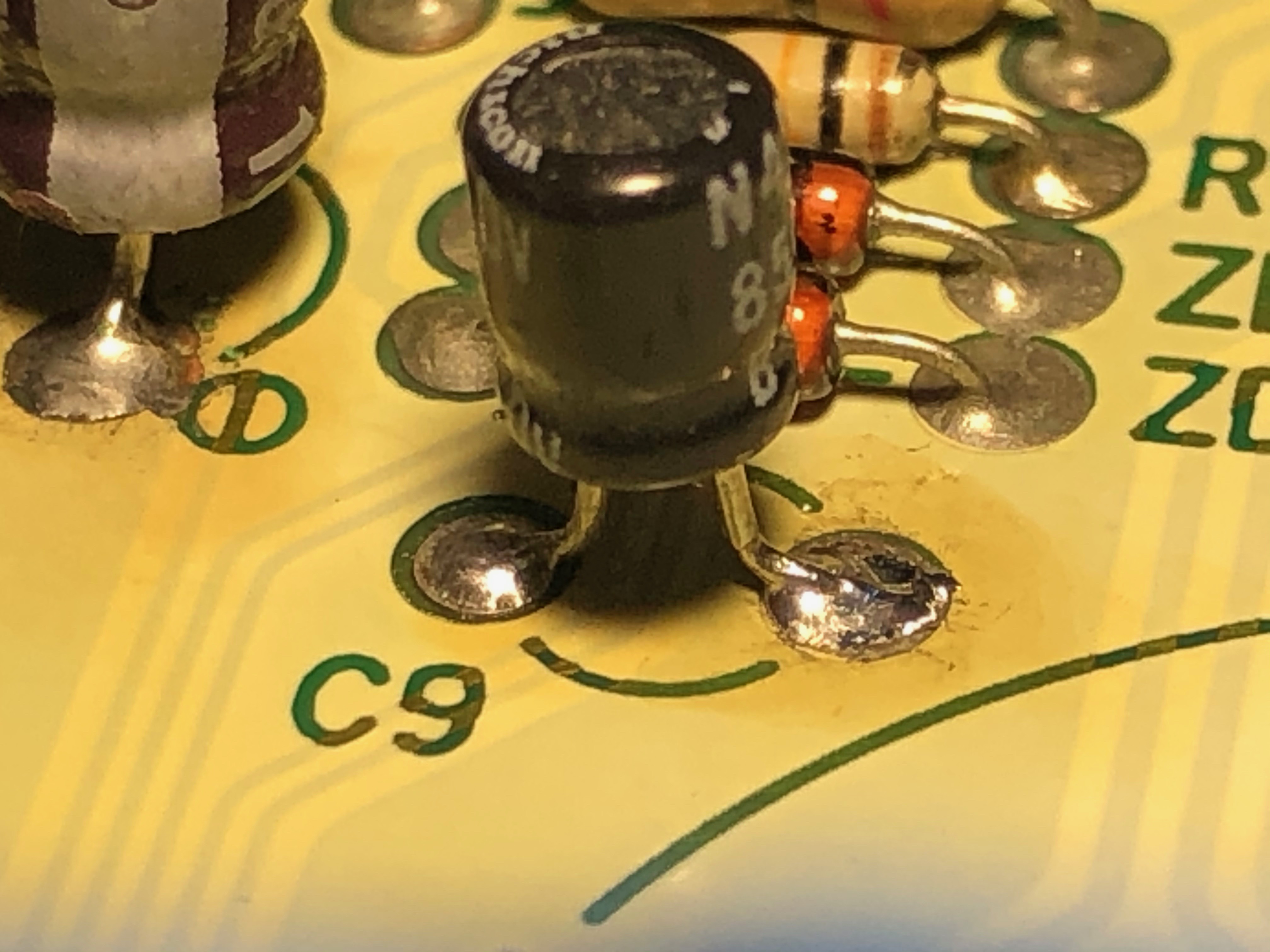
Next, you may want to replace the solder on C9. One solder joint looks a bit rough and it should be smooth like the others. Just re-solder the scraggly joint.
IMO, I would stick to the standard light bulbs in the cluster. The cluster uses pulse width modulation to control the brightness of the bulbs. LED bulbs may not work properly in this type of system. Others members are free to offer better advise or share their experiences on the matter. Or I'm sure a quick search will yield some answers on that topic.
Again, great job at soldering in the new capacitors!
Stick to getting your speedo board repaired first. So hold off on replacing the caps on the tach and CPU#2. Once we verify everything works then you could replace them.
Based upon your photos, take a hard look at TR7. Specifically, its center leg. It looks either broken or a cold joint. You may need to re-solder that leg. Be VERY careful though! You do not want to loose that leg. You could post additional photos of TR7 before doing any additional work to it.
Next, you may want to replace the solder on C9. One solder joint looks a bit rough and it should be smooth like the others. Just re-solder the scraggly joint.
IMO, I would stick to the standard light bulbs in the cluster. The cluster uses pulse width modulation to control the brightness of the bulbs. LED bulbs may not work properly in this type of system. Others members are free to offer better advise or share their experiences on the matter. Or I'm sure a quick search will yield some answers on that topic.
Again, great job at soldering in the new capacitors!
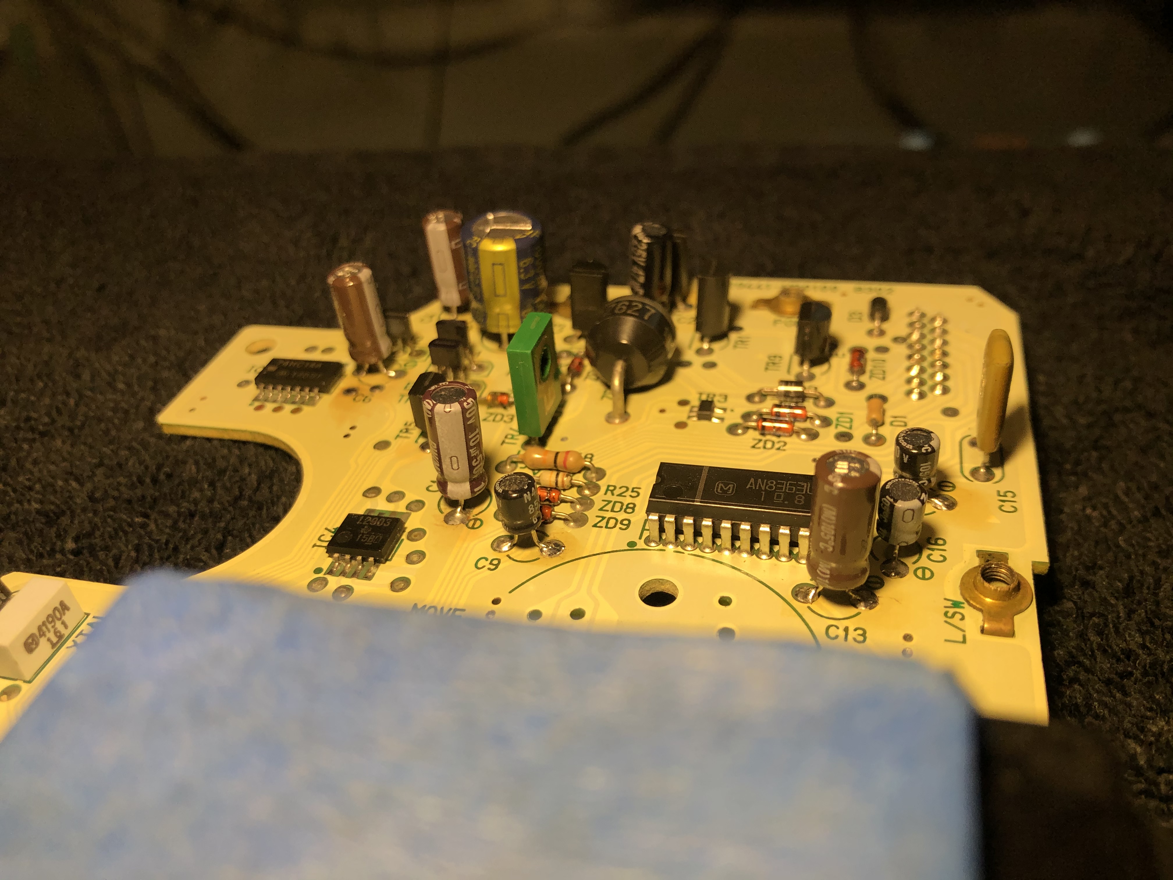
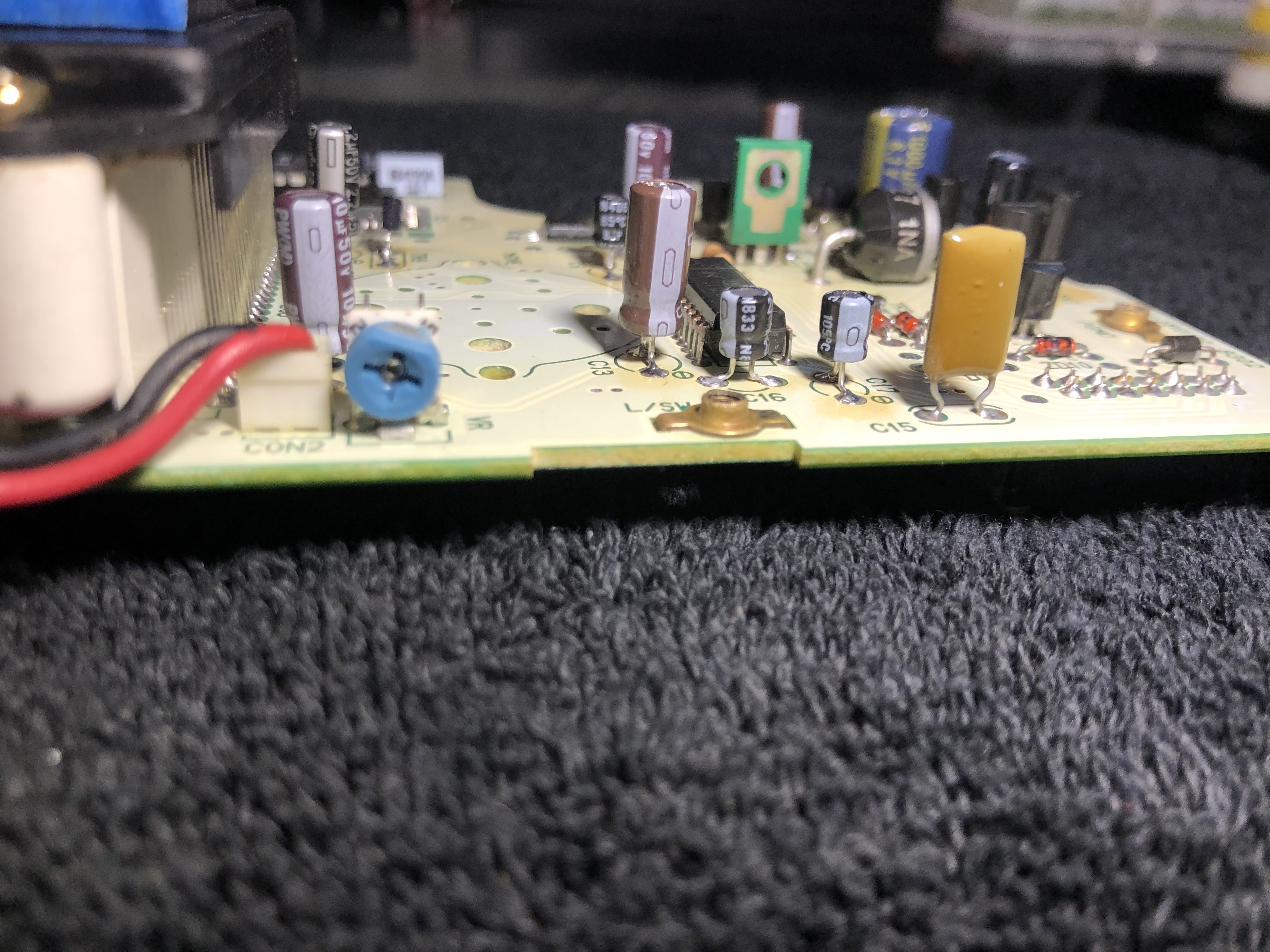
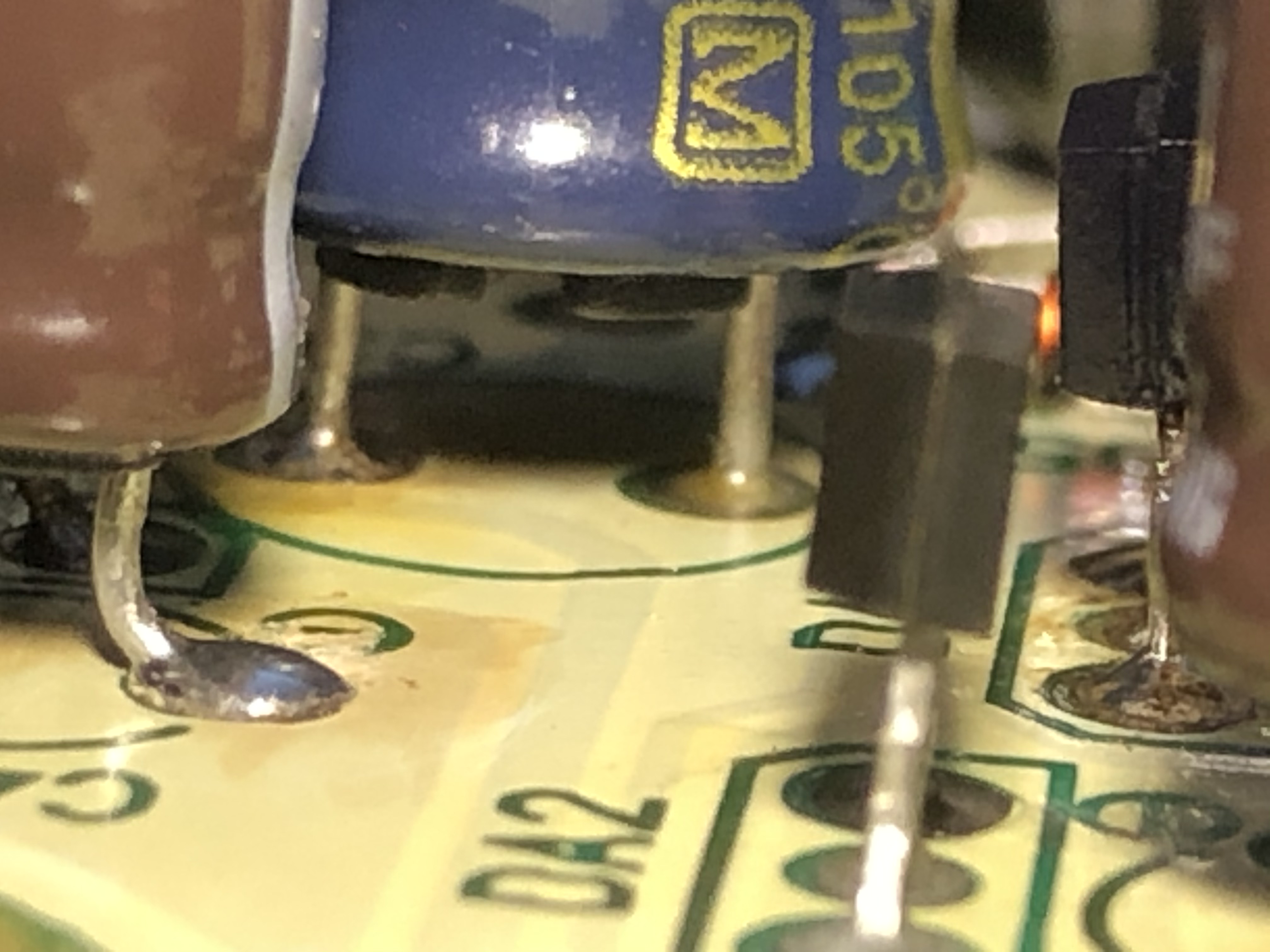
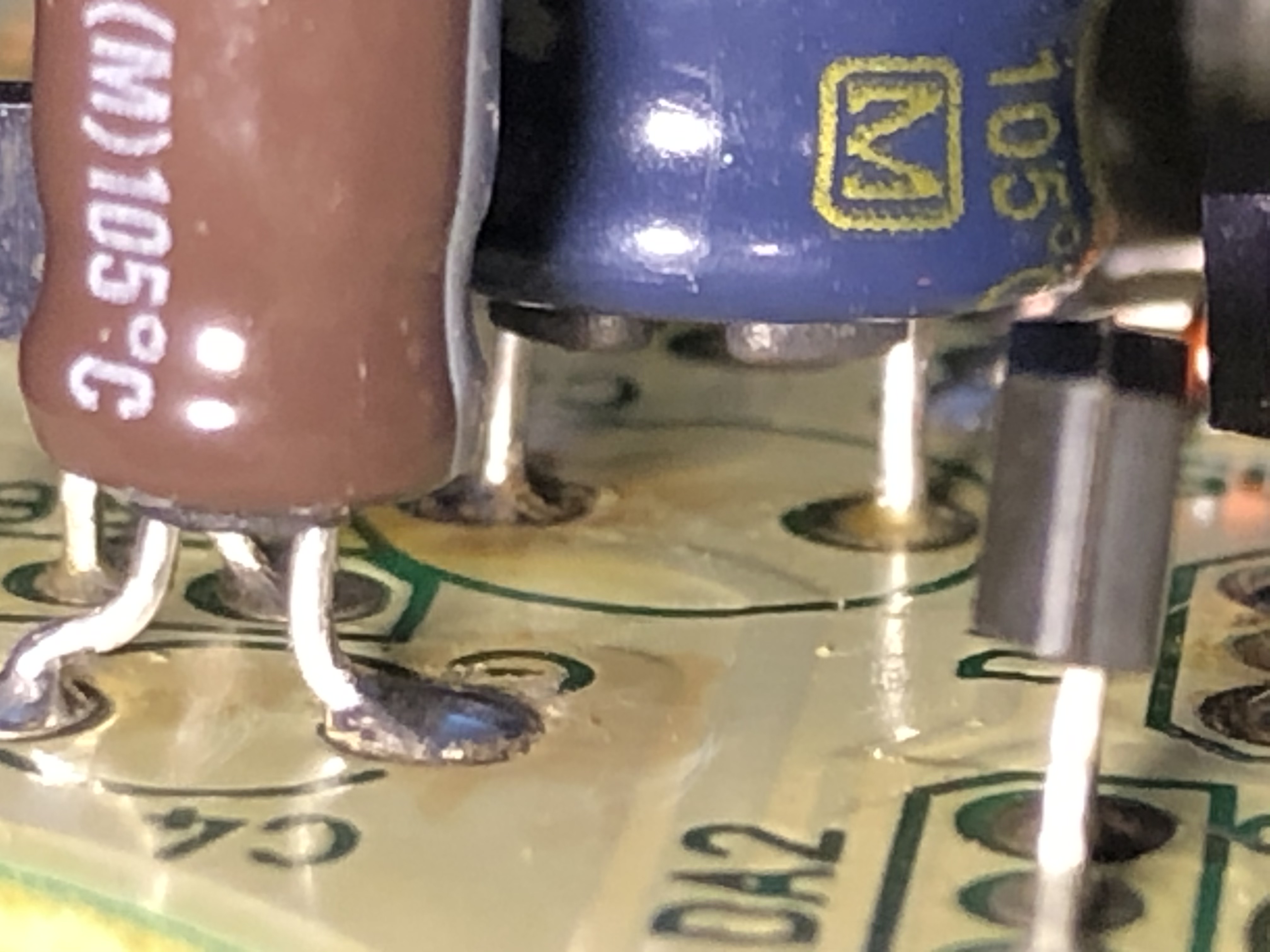
C3:

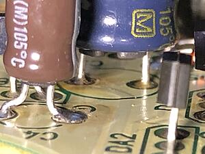

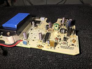
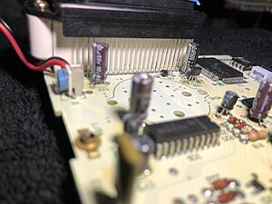
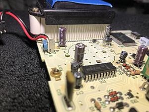
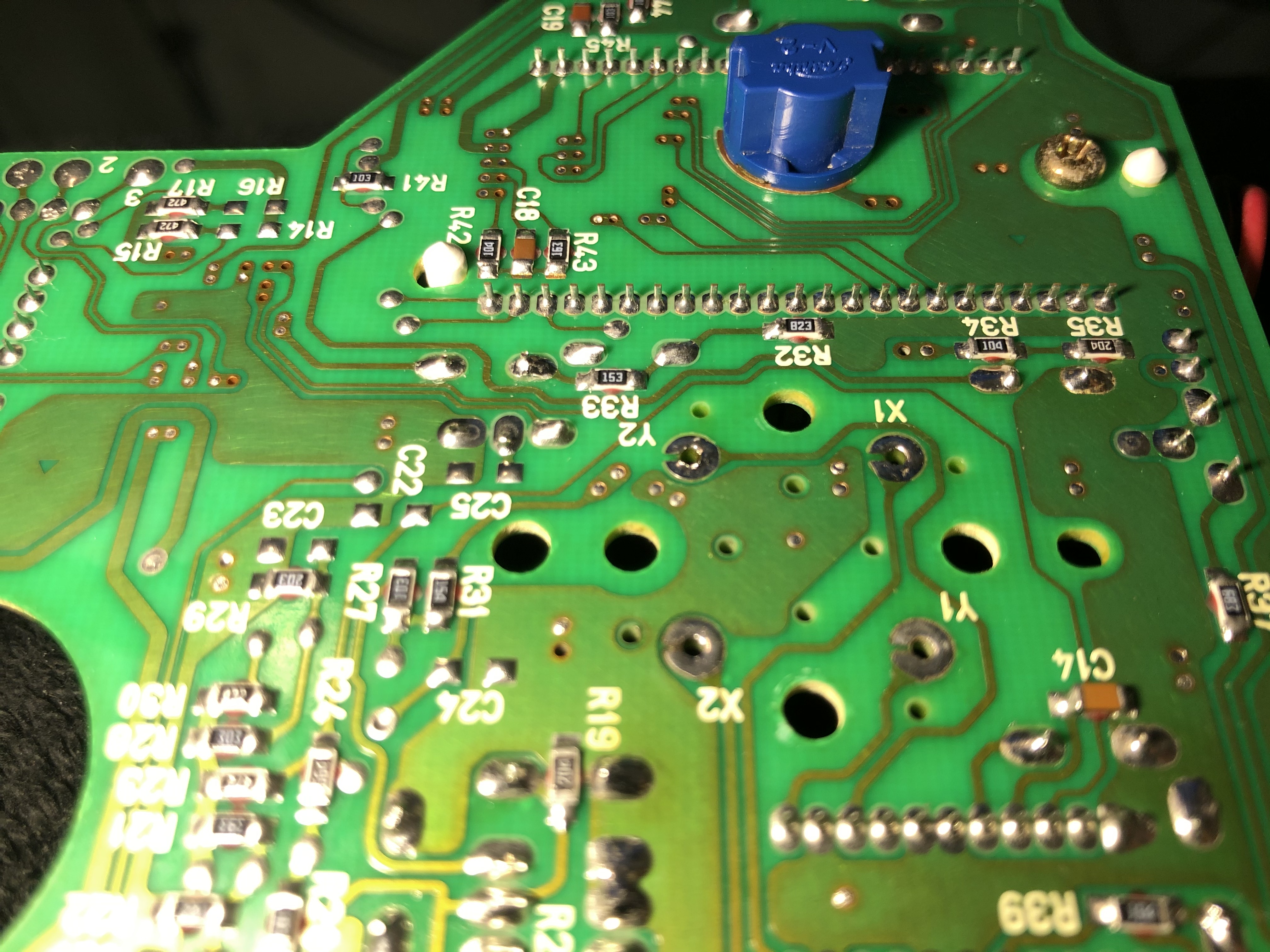
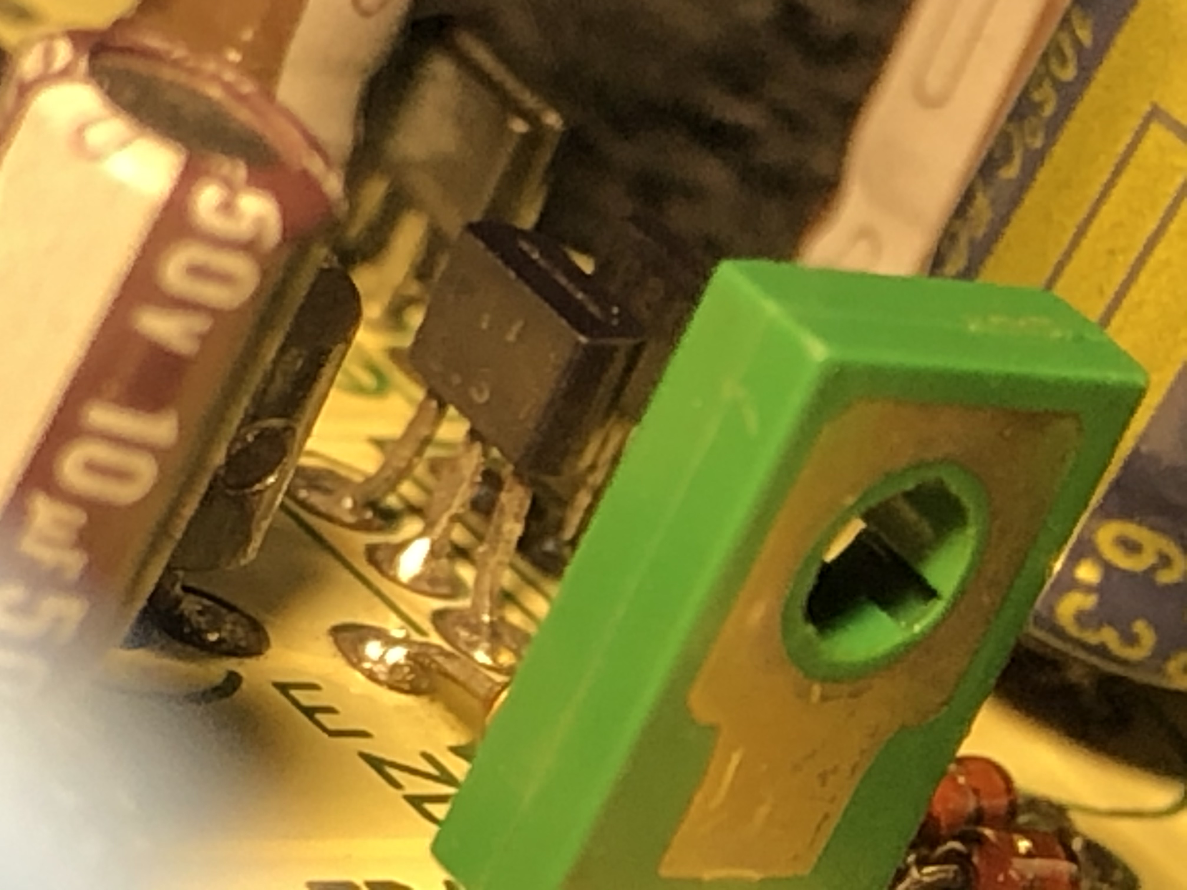
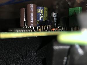
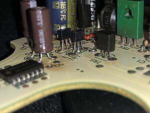
TR7: Unaltered component since my last post, zoomed in. DA1 appears to be spindly looking to me? I could doctor it up?
C9: I can go over it again, I was erring on the side of caution as this is the side/leg with the large trace on the back side, and I felt I was adding more heat than was necessary and not getting better results with flowout.
If you have any specific direction to help in this regard, I think/know I could get it to work better by preheating the board or some other method to help prohibit sinking, while keeping the component temperature low.
Are there any other points of contention I could zoom in on or highlight better?
Any existing components that might be good to clean up better?
TR7: Unaltered component since my last post, zoomed in. DA1 appears to be spindly looking to me? I could doctor it up?

C9: I can go over it again, I was erring on the side of caution as this is the side/leg with the large trace on the back side, and I felt I was adding more heat than was necessary and not getting better results with flowout.
If you have any specific direction to help in this regard, I think/know I could get it to work better by preheating the board or some other method to help prohibit sinking, while keeping the component temperature low.
Are there any other points of contention I could zoom in on or highlight better?
Any existing components that might be good to clean up better?
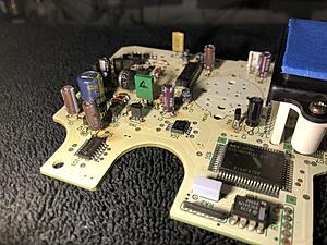
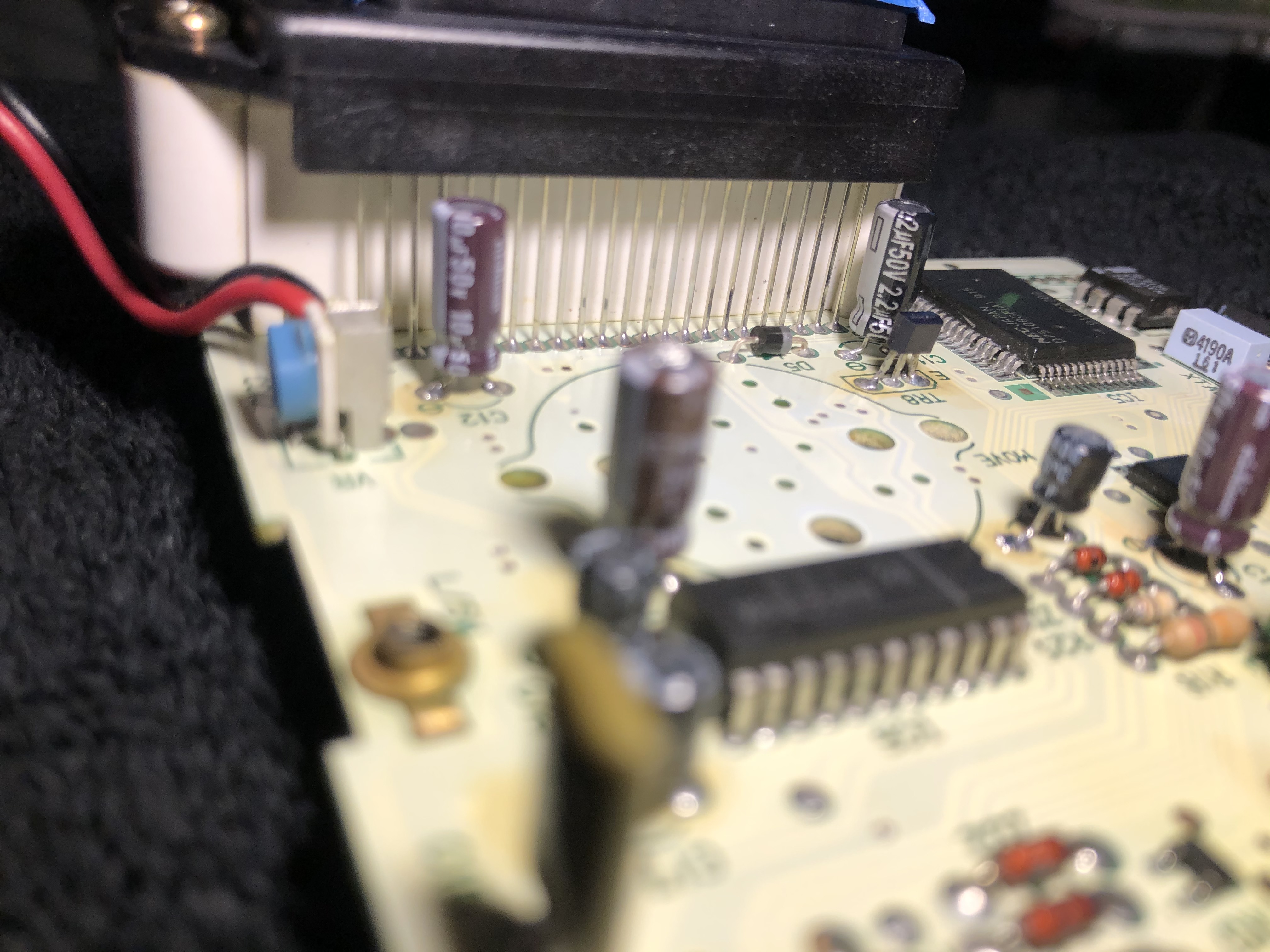
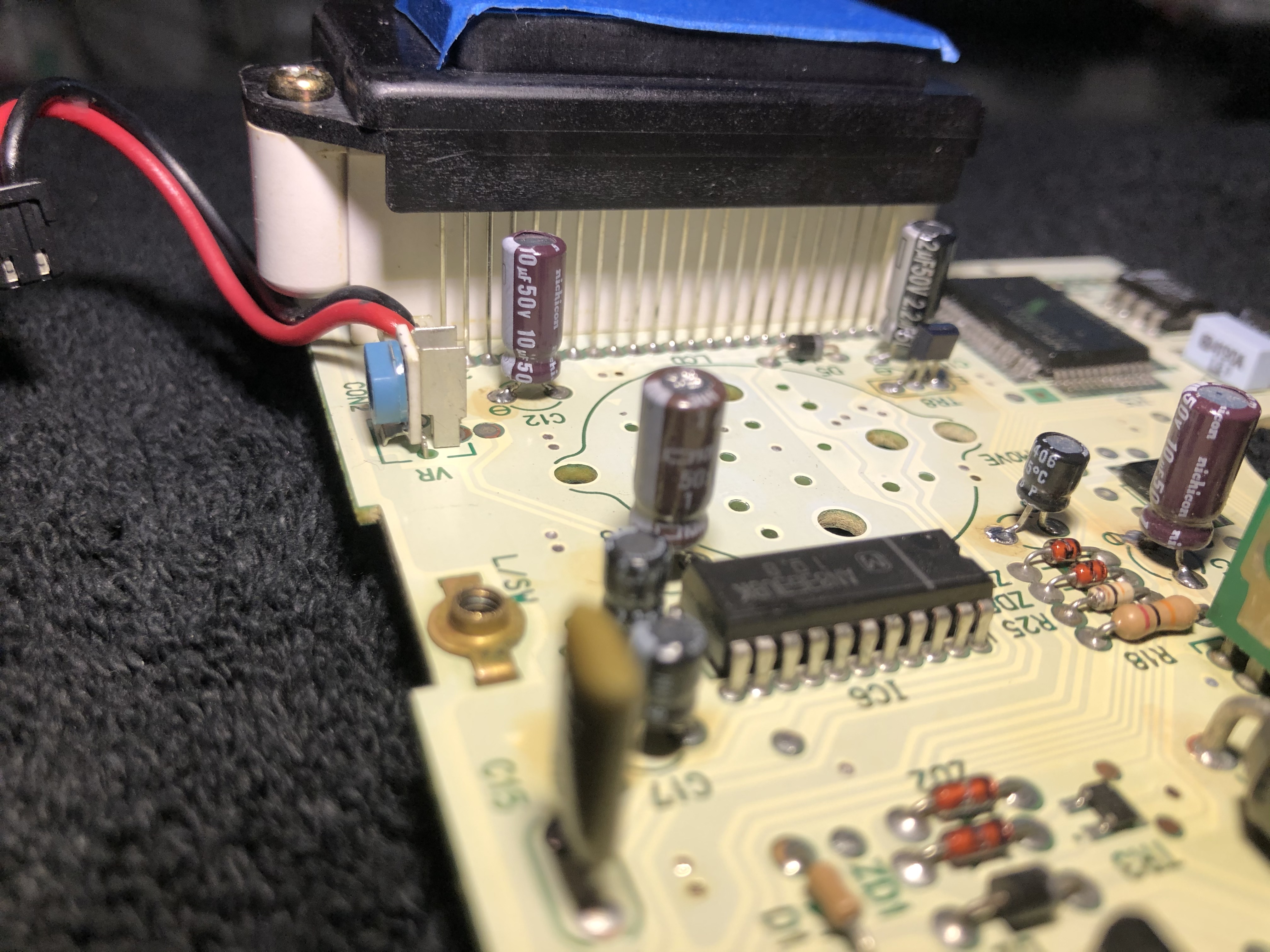
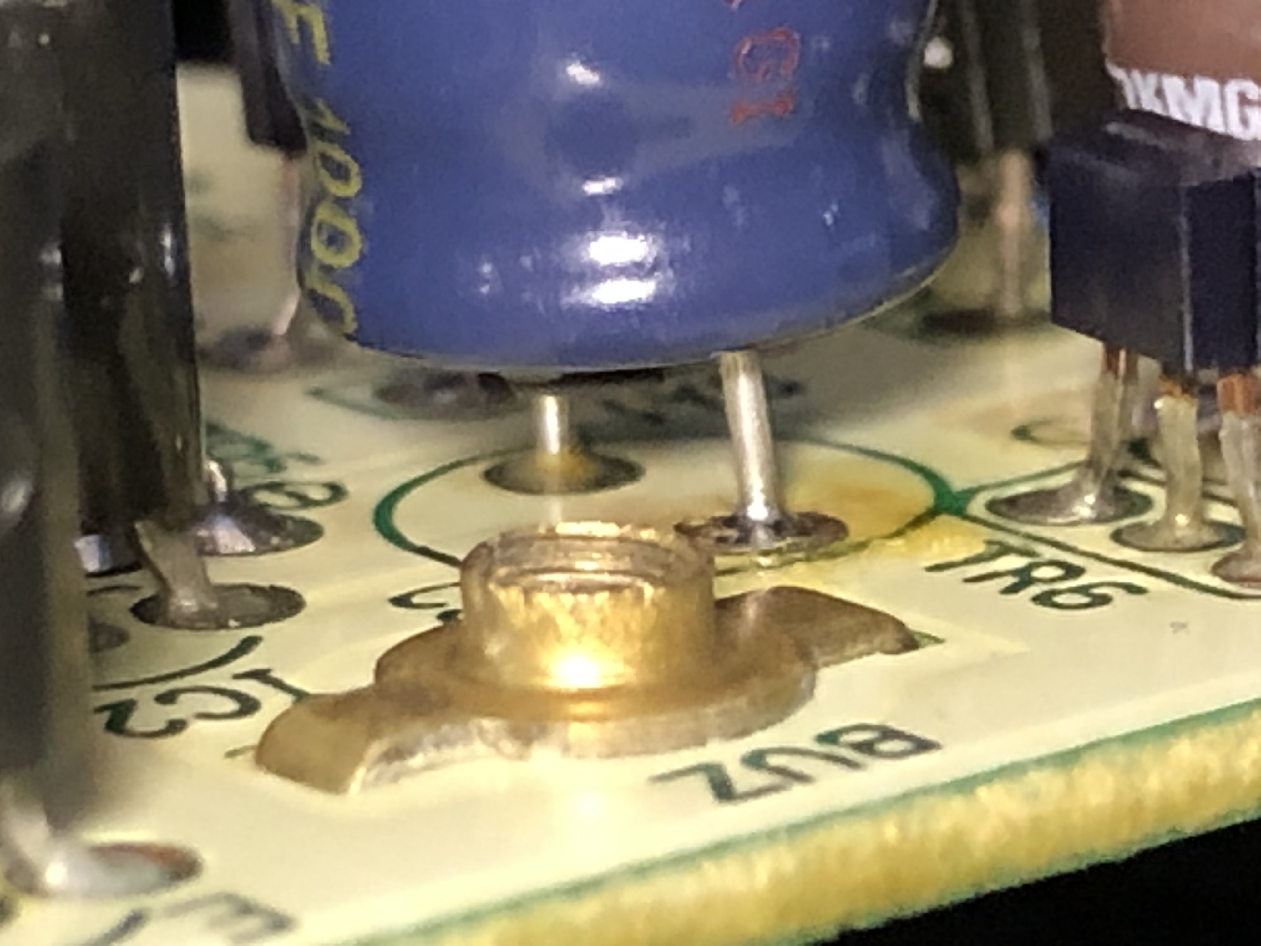
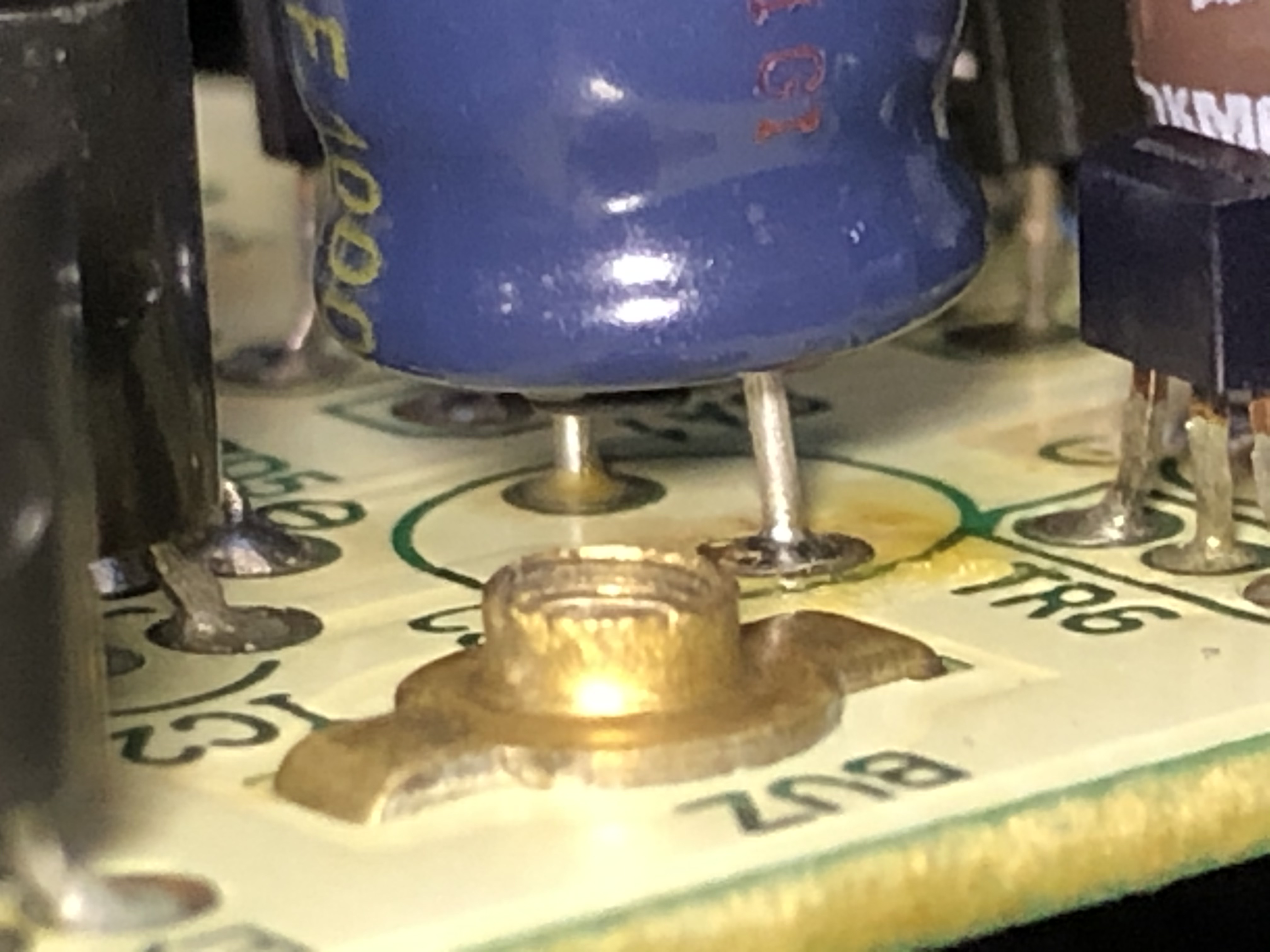
Some additional TR7 and DA1, because they are of heightened concern for me above almost anything else. I feel like they should be replaced, or perhaps removed thoroughly cleaned and reworked.


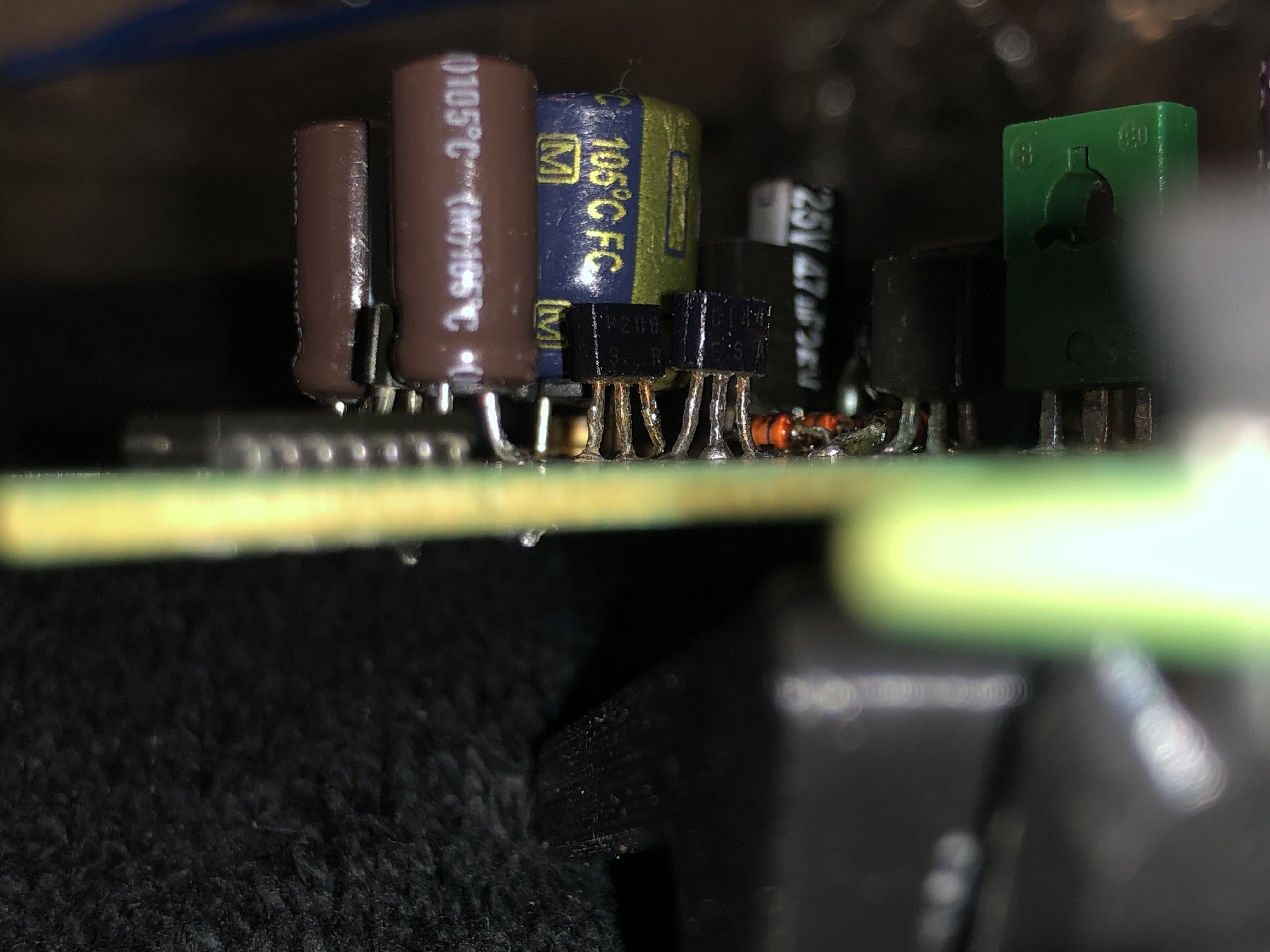

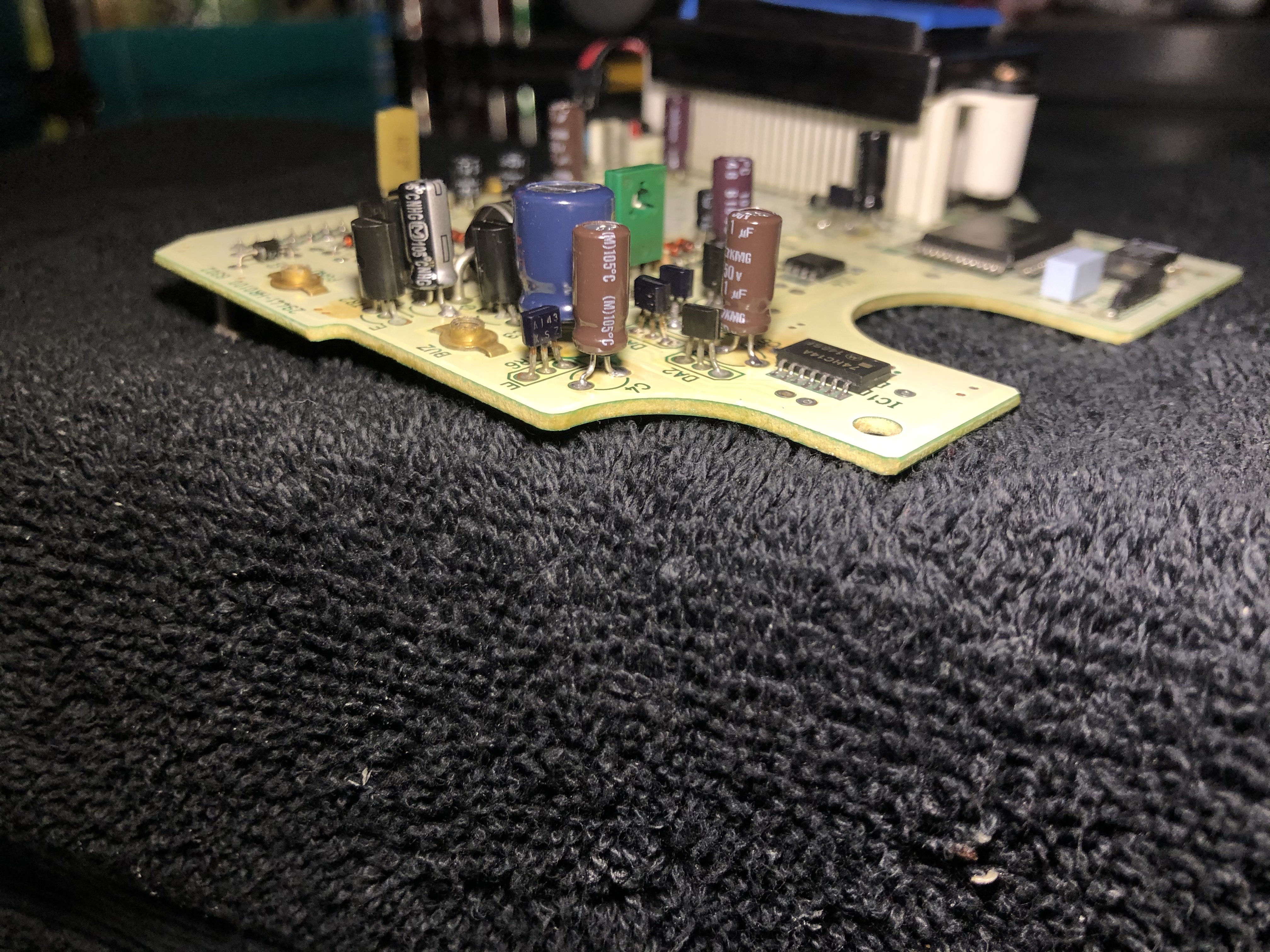
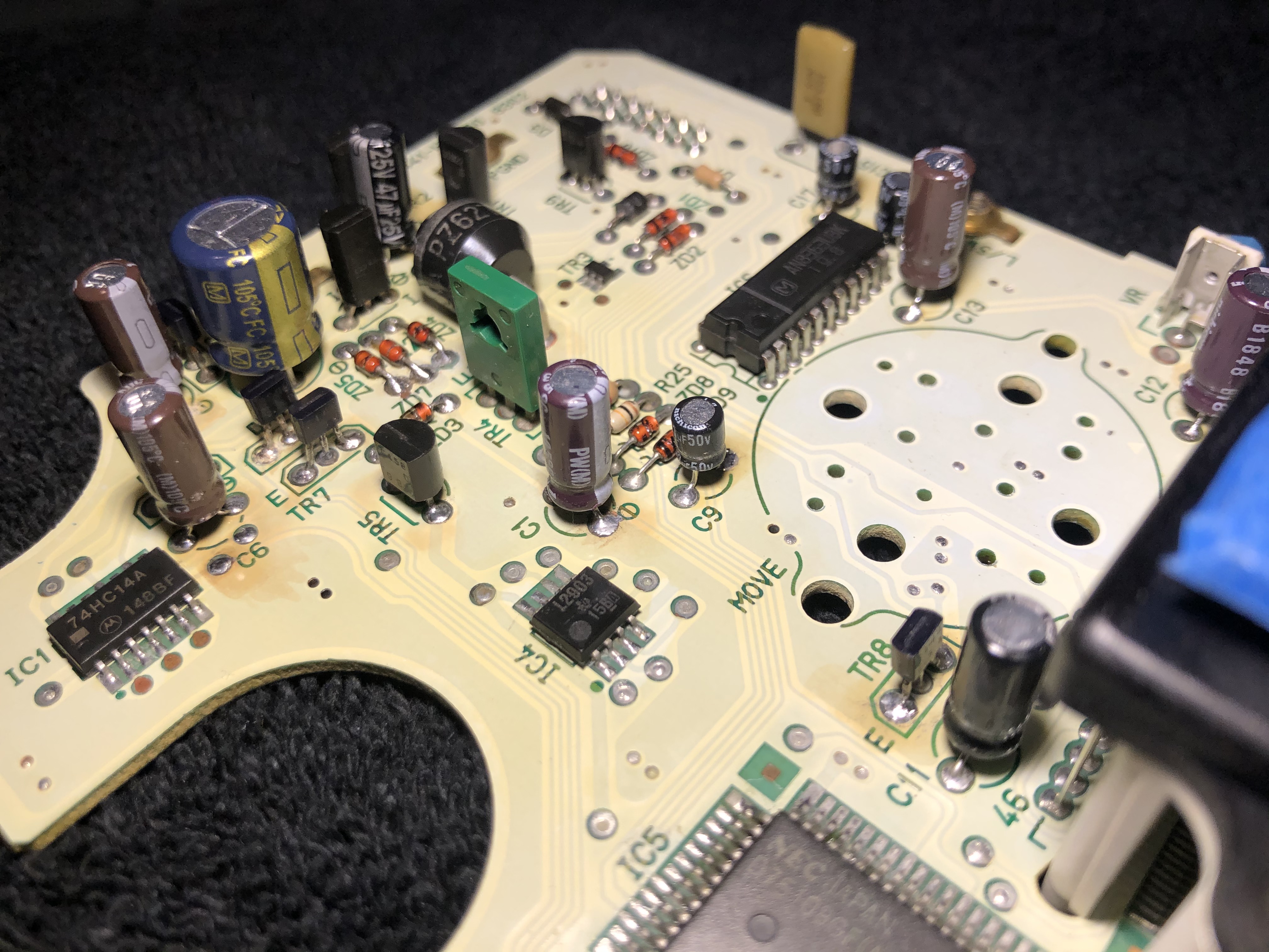
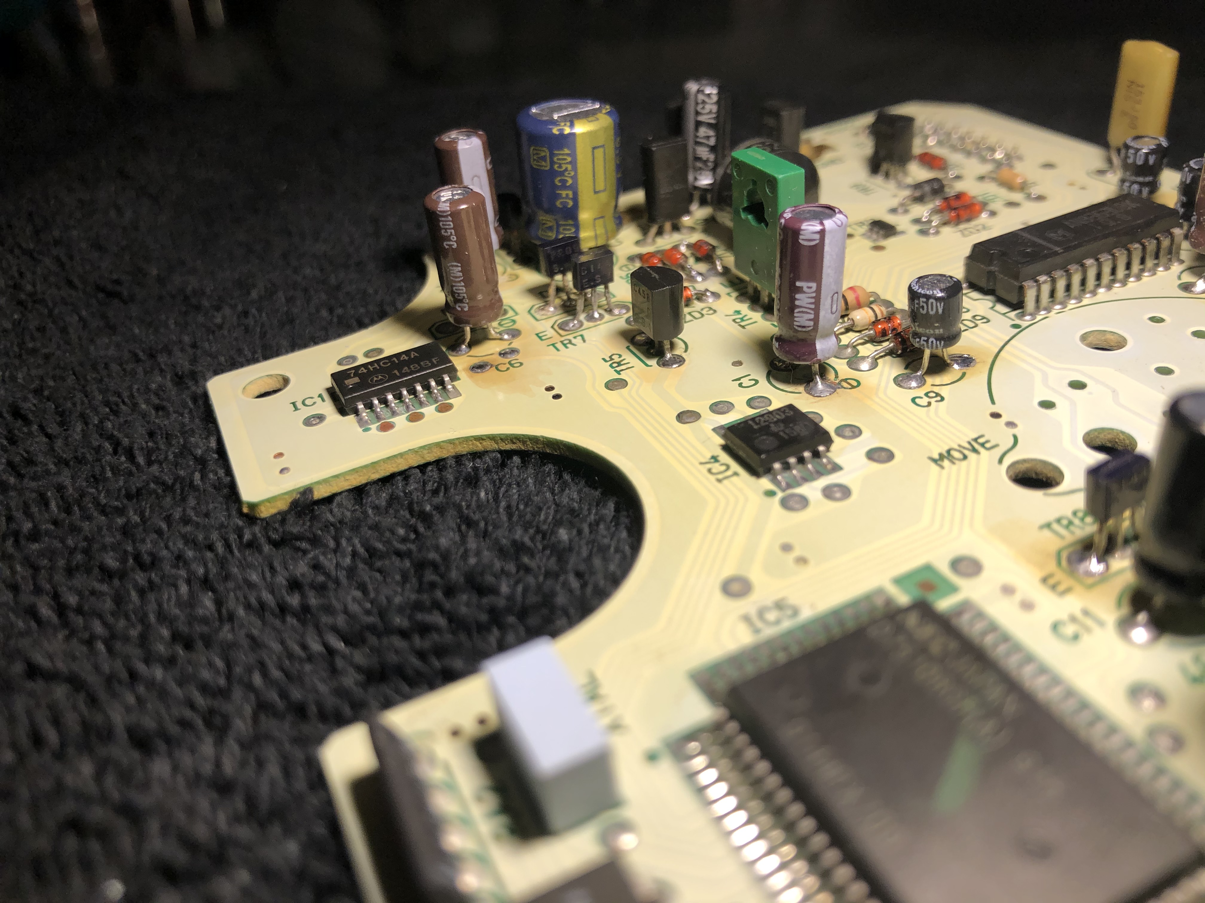
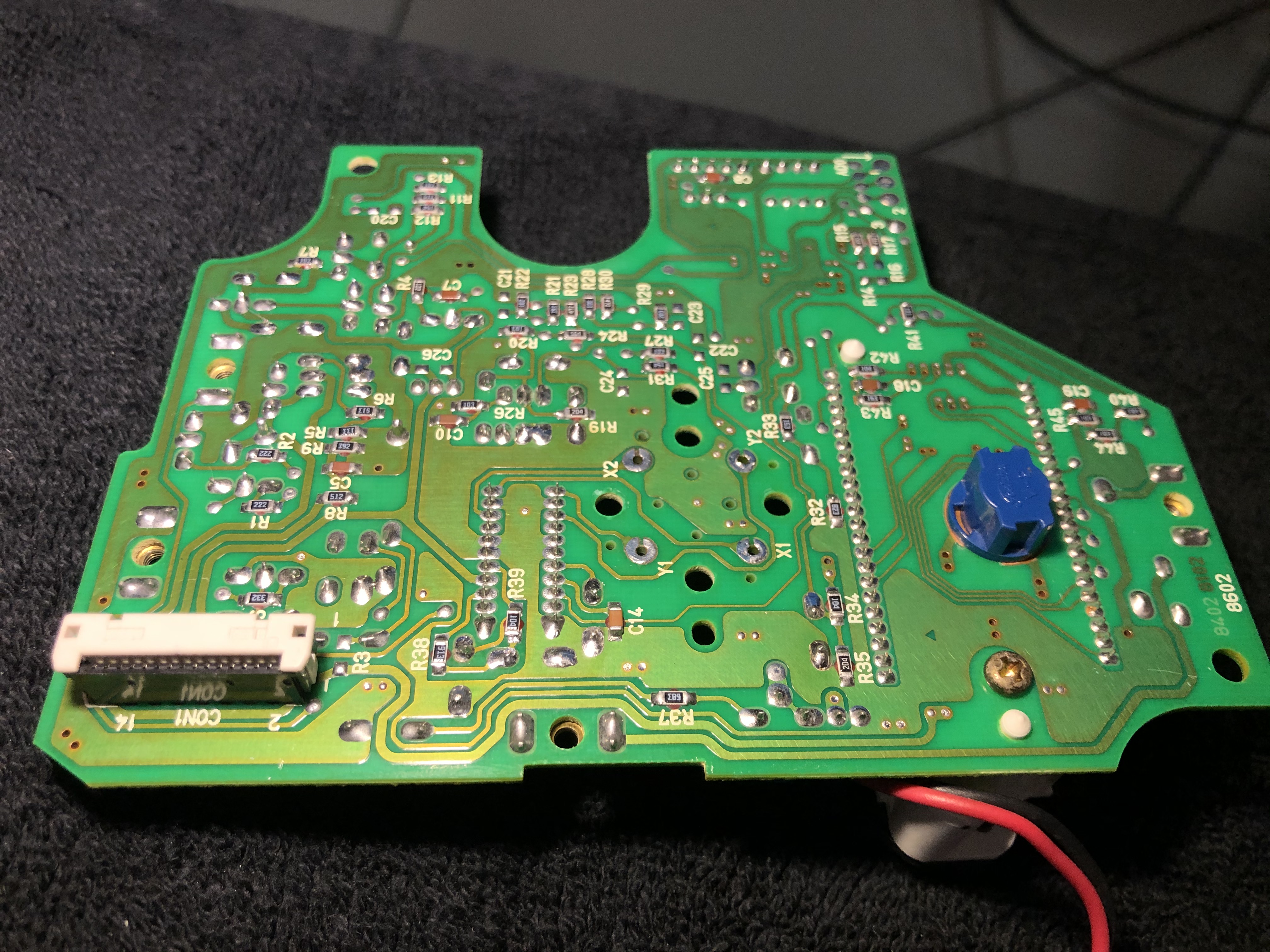
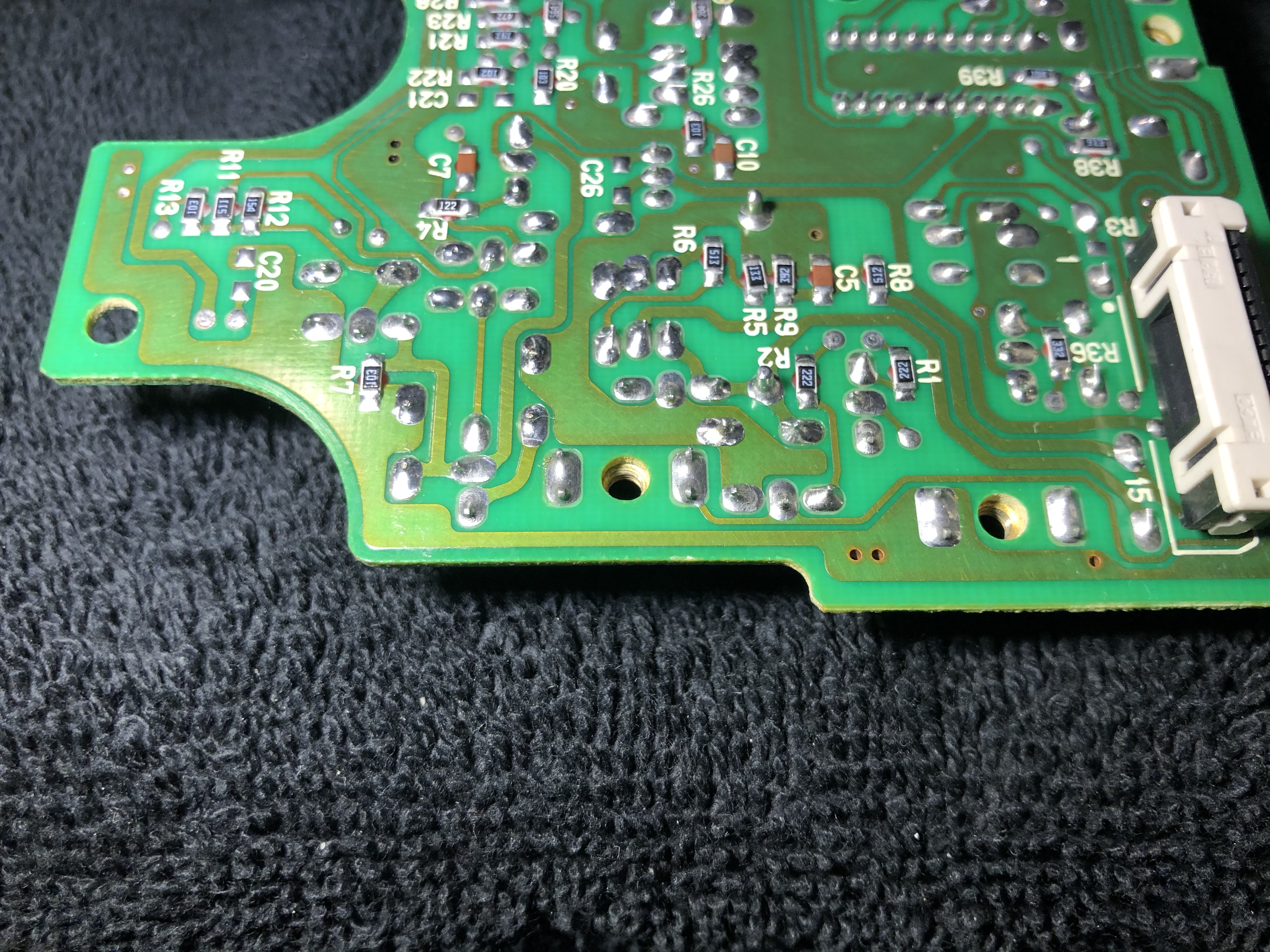
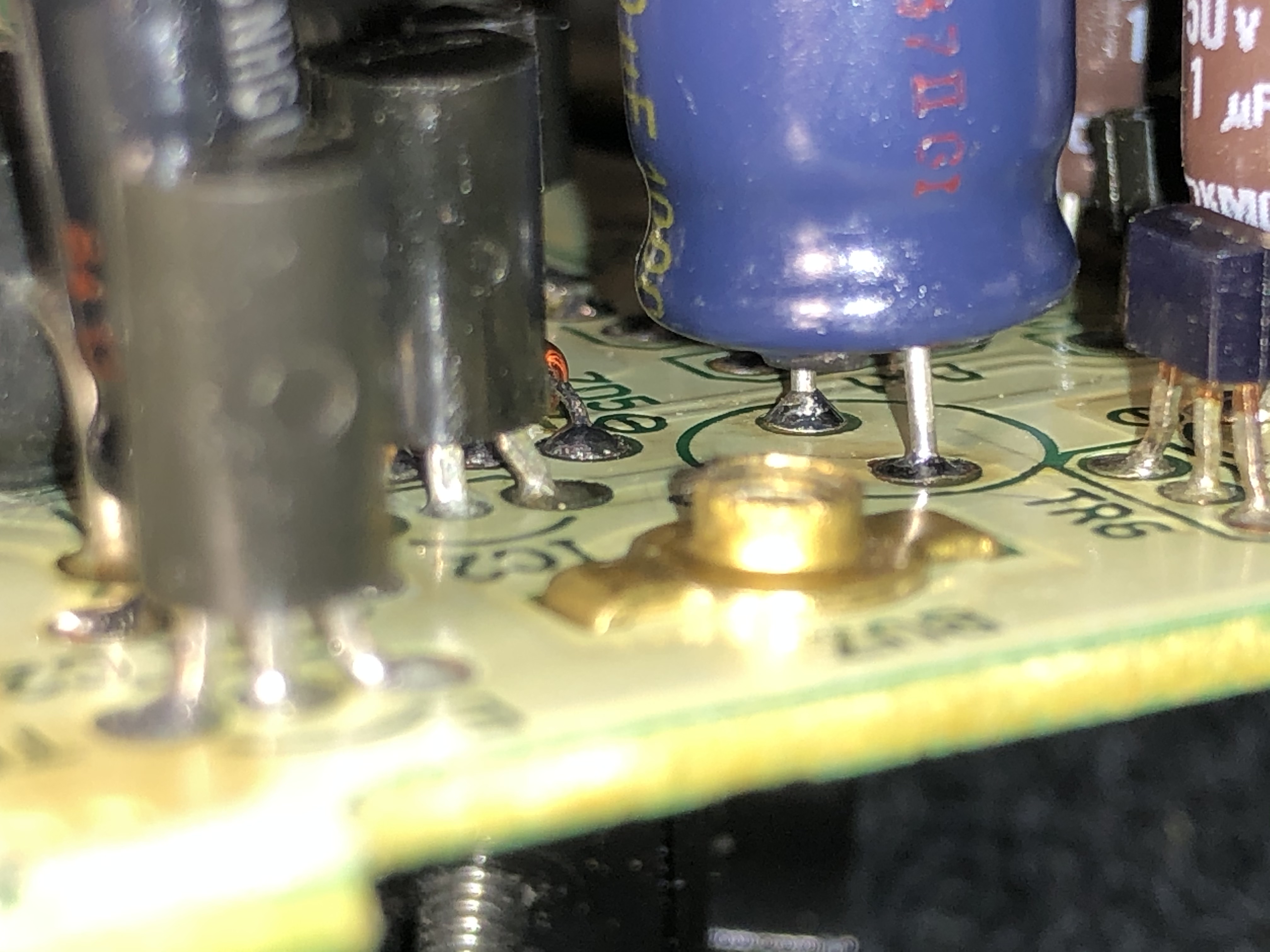
Test that side of C9 with a DMM. Have one lead touch the leg above the solder joint then touch the other lead to another joint along the ground plane (on the back side). It should measure a dead short. If it measures fine then don't mess with it.
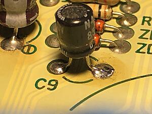
Is that flux on around the positive leg of C3? Clean it off with some isopropyl alcohol. That positive leg of C3 looks very similar to C9. Test that positive leg of C3 in the same manner as C9. Except put the second lead on the emitter of TR6 (labeled as "E"). Again, if it reads a dead short then leave it be.
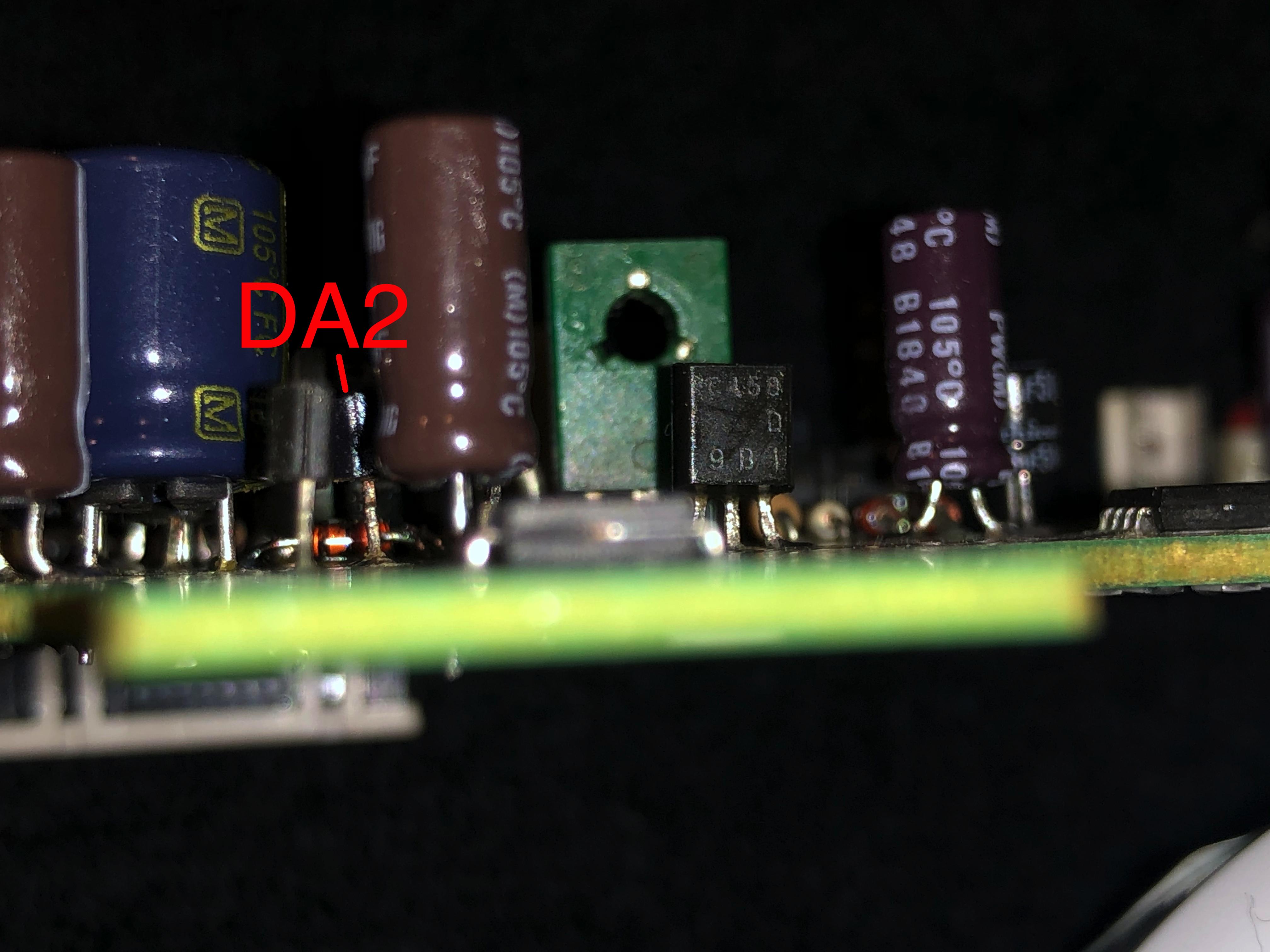
I swear, my eyes are playing tricks on me. Take a second look at your first photo of C3. The legs of DA1 look extraordinarily thin. That may interference with C6. Whatever you do, don't play with DA1. If the legs are the same thickness as DA2 then don't worry about it. Unless absolutely necessary, do not mess with the legs of any other component on this board, especially those components that surround C3.
If everything tests good then you may go forward with the testing phase.
To test, partially assemble the instrument cluster. Place the clear lens on the face of the cluster. Don't forget to plug in your speedo cable at CON1. Otherwise you will have a dead speedo, odo, and tach. You can temporarily rest the cluster (without the hood) on top of the steering wheel column. Take deliberate steps to turn the ignition cylinder through each position - ACC and ON. Your odo should display its reading when the ignition is in the ON position (and engine not running). It may take several seconds because the capacitors have to charge. If it doesn't turn on yet, then that's fine. Just note it. While the ignition switch is in the ON position, pay special attention to the speedo board. You are looking for the "magic smoke". If you see/hear something burn then immediately shut the car down. Do your best to note where the magic smoke comes from. That is just a precaution - it shouldn't be necessary but always be vigilant and have a plan for a smoke check.
If everything appears to be fine then go ahead and start up the car. Allow it to warm up then test for the over-rev buzzer. Pay attention to the needles on your tach and speedo. Does the speedo needle follow the tach? Remember, that was noted during one of your videos. Does the RPM needle match your PFC? Do you no longer hear the over-rev buzzer above 2,500 RPM? Can you see your odometer? If everything looks good then shut it down so you may properly reassembly the instrument cluster to the hood. Once things are back together then go ahead and give it a low-speed (25-35 MPH) test run. Verify that your speedometer and odometer work. Don't forget to check the tripometer too! It (the trip meter) would be reset to 0 miles anyway. Drive a 1mi loop for this quick test.
Is that flux on around the positive leg of C3? Clean it off with some isopropyl alcohol. That positive leg of C3 looks very similar to C9. Test that positive leg of C3 in the same manner as C9. Except put the second lead on the emitter of TR6 (labeled as "E"). Again, if it reads a dead short then leave it be.
I swear, my eyes are playing tricks on me. Take a second look at your first photo of C3. The legs of DA1 look extraordinarily thin. That may interference with C6. Whatever you do, don't play with DA1. If the legs are the same thickness as DA2 then don't worry about it. Unless absolutely necessary, do not mess with the legs of any other component on this board, especially those components that surround C3.
If everything tests good then you may go forward with the testing phase.
To test, partially assemble the instrument cluster. Place the clear lens on the face of the cluster. Don't forget to plug in your speedo cable at CON1. Otherwise you will have a dead speedo, odo, and tach. You can temporarily rest the cluster (without the hood) on top of the steering wheel column. Take deliberate steps to turn the ignition cylinder through each position - ACC and ON. Your odo should display its reading when the ignition is in the ON position (and engine not running). It may take several seconds because the capacitors have to charge. If it doesn't turn on yet, then that's fine. Just note it. While the ignition switch is in the ON position, pay special attention to the speedo board. You are looking for the "magic smoke". If you see/hear something burn then immediately shut the car down. Do your best to note where the magic smoke comes from. That is just a precaution - it shouldn't be necessary but always be vigilant and have a plan for a smoke check.
If everything appears to be fine then go ahead and start up the car. Allow it to warm up then test for the over-rev buzzer. Pay attention to the needles on your tach and speedo. Does the speedo needle follow the tach? Remember, that was noted during one of your videos. Does the RPM needle match your PFC? Do you no longer hear the over-rev buzzer above 2,500 RPM? Can you see your odometer? If everything looks good then shut it down so you may properly reassembly the instrument cluster to the hood. Once things are back together then go ahead and give it a low-speed (25-35 MPH) test run. Verify that your speedometer and odometer work. Don't forget to check the tripometer too! It (the trip meter) would be reset to 0 miles anyway. Drive a 1mi loop for this quick test.
Test that side of C9 with a DMM. Have one lead touch the leg above the solder joint then touch the other lead to another joint along the ground plane (on the back side). It should measure a dead short. If it measures fine then don't mess with it.
Is that flux on around the positive leg of C3? Clean it off with some isopropyl alcohol. That positive leg of C3 looks very similar to C9. Test that positive leg of C3 in the same manner as C9. Except put the second lead on the emitter of TR6 (labeled as "E"). Again, if it reads a dead short then leave it be.
I swear, my eyes are playing tricks on me. Take a second look at your first photo of C3. The legs of DA1 look extraordinarily thin. That may interference with C6. Whatever you do, don't play with DA1. If the legs are the same thickness as DA2 then don't worry about it. Unless absolutely necessary, do not mess with the legs of any other component on this board, especially those components that surround C3.
I am including new side shots of DA1 and TR7 from approximately similar positioning, trying to highlight this leg.
If everything tests good then you may go forward with the testing phase.
To test, partially assemble the instrument cluster. Place the clear lens on the face of the cluster. Don't forget to plug in your speedo cable at CON1. Otherwise you will have a dead speedo, odo, and tach. You can temporarily rest the cluster (without the hood) on top of the steering wheel column. Take deliberate steps to turn the ignition cylinder through each position - ACC and ON. Your odo should display its reading when the ignition is in the ON position (and engine not running). It may take several seconds because the capacitors have to charge. If it doesn't turn on yet, then that's fine. Just note it. While the ignition switch is in the ON position, pay special attention to the speedo board. You are looking for the "magic smoke". If you see/hear something burn then immediately shut the car down. Do your best to note where the magic smoke comes from. That is just a precaution - it shouldn't be necessary but always be vigilant and have a plan for a smoke check.
If everything appears to be fine then go ahead and start up the car. Allow it to warm up then test for the over-rev buzzer. Pay attention to the needles on your tach and speedo. Does the speedo needle follow the tach? Remember, that was noted during one of your videos. Does the RPM needle match your PFC? Do you no longer hear the over-rev buzzer above 2,500 RPM? Can you see your odometer? If everything looks good then shut it down so you may properly reassembly the instrument cluster to the hood. Once things are back together then go ahead and give it a low-speed (25-35 MPH) test run. Verify that your speedometer and odometer work. Don't forget to check the tripometer too! It (the trip meter) would be reset to 0 miles anyway. Drive a 1mi loop for this quick test.
Leave the solder joints alone for now. If there any issues then we may need to tidy them up. The reasons for the hesitation are: heat cycling components and playing with a solder joint. If there is a good mechanical bond and electrical bond then it should be fine.
Let me know how your project turns out!
Let me know how your project turns out!
To test, partially assemble the instrument cluster. Place the clear lens on the face of the cluster. Don't forget to plug in your speedo cable at CON1. Otherwise you will have a dead speedo, odo, and tach. You can temporarily rest the cluster (without the hood) on top of the steering wheel column. Take deliberate steps to turn the ignition cylinder through each position - ACC and ON. Your odo should display its reading when the ignition is in the ON position (and engine not running). It may take several seconds because the capacitors have to charge. If it doesn't turn on yet, then that's fine. Just note it. While the ignition switch is in the ON position, pay special attention to the speedo board. You are looking for the "magic smoke". If you see/hear something burn then immediately shut the car down. Do your best to note where the magic smoke comes from. That is just a precaution - it shouldn't be necessary but always be vigilant and have a plan for a smoke check.
The odometer does not read at the ON position even after several seconds in the ON position, Sounds like this was expected, or at least not surprising?
If important, the odometer did work "Normally" before disassembly, and was lit and active with No issues of intermittent operation before as seems to be common from searching briefly on the topic.
I recorded the ACC and ON procedure if there is any detail you wish to know or have clarified.
As far as I can tell all typical functionality except the odometer is operational.
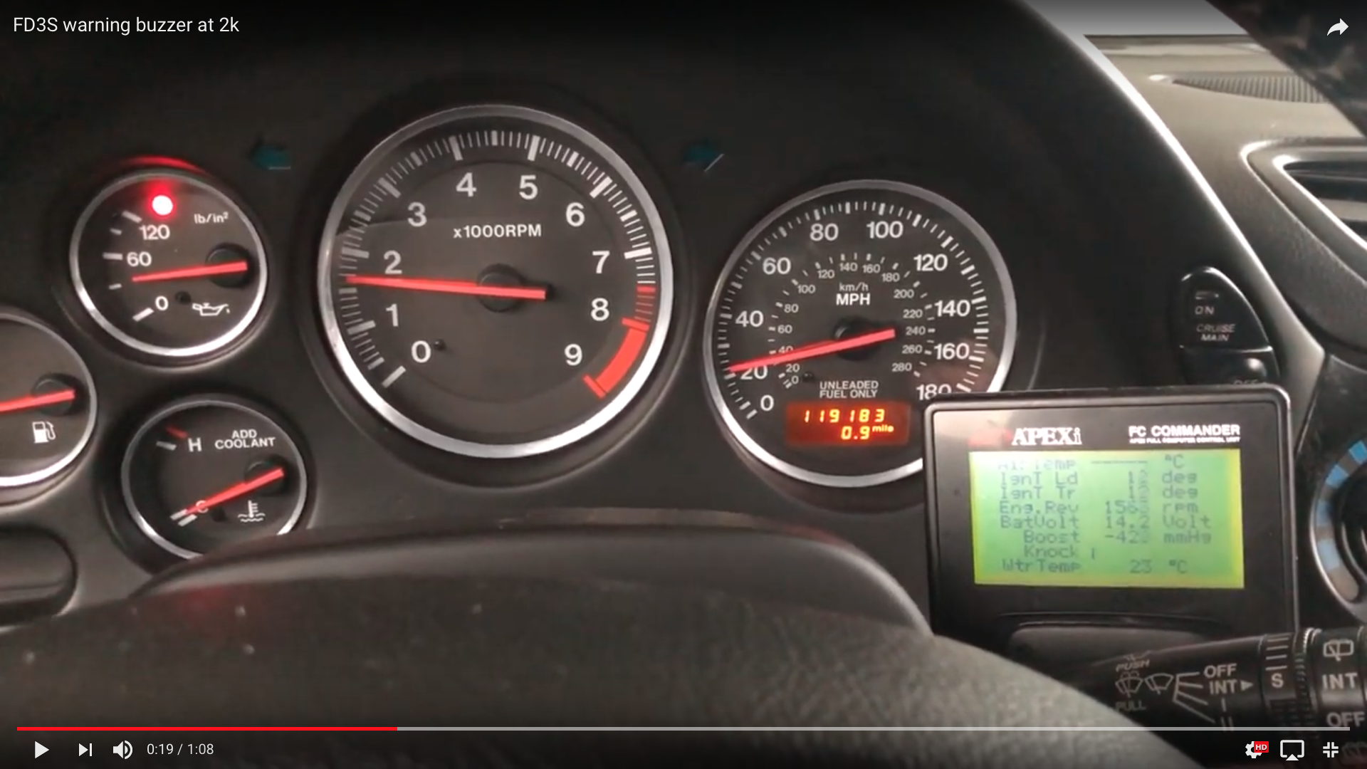
No over rev buzzer detected at 2k as before, or in the cruising RPM range above 2k, can test activation point if/when requested. (to remove doubt if you recall, I did make a pigtail plug for my buzzer while repairing, this was plugged in if it was a question)
Tach appears to follow PFC closely as before.
If everything appears to be fine then go ahead and start up the car. Allow it to warm up then test for the over-rev buzzer. Pay attention to the needles on your tach and speedo. Does the speedo needle follow the tach? Remember, that was noted during one of your videos. Does the RPM needle match your PFC? Do you no longer hear the over-rev buzzer above 2,500 RPM? Can you see your odometer? If everything looks good then shut it down so you may properly reassembly the instrument cluster to the hood. Once things are back together then go ahead and give it a low-speed (25-35 MPH) test run. Verify that your speedometer and odometer work. Don't forget to check the tripometer too! It (the trip meter) would be reset to 0 miles anyway. Drive a 1mi loop for this quick test.
I still cannot see my odometer after a 15 min warm up and a short 5 minute drive.
The speedo appears to be ~correct, as I conveniently have a Radar speed sign just down the street from me despite being in a very rural area, assuming acuracy would at all be in question. Sweeps through the range as would be normal and expected as does the Tach.
*Assuming you might see this late at night around the time of posting as it appears you get notifications, please do not trouble yourself with replying, just overly excited that it appears to have been successful so far!
Incredibly grateful you are willing to expend the time and effort to detail something so meticulously one on one!
THANK YOU!

Last edited by rotarypower101; Feb 29, 2020 at 03:03 AM.
Well, what the hell do you know...,was it just the Backlight...
Somehow it went out between making that video a few days ago and now, while Not in use...
What are the chances of that happening Before, and Not After I have reassembled everything!!!
Am I interpreting that correctly? The segment display digits could not be seen before swapping over the gas gauge bulb to test.
Or are the digits perhaps not illuminating as brightly? They appear daylight readable bright in my daytime "before" photo, yet only as intense as the backlight in the night photo. But is not readable unless the lights are on to activate backlighting.
I can’t think of anything that would have caused the bulb to go out, I am a big proponent of cutting battery power before plugging and unplugging anything. As well as I did cycle positive battery power while all plugged in on the advice of another thread.
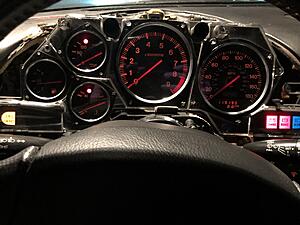
The other daylight "Before" shots of the odometer working and tonight After changing out the bulb in the dark.
Somehow it went out between making that video a few days ago and now, while Not in use...
What are the chances of that happening Before, and Not After I have reassembled everything!!!
Am I interpreting that correctly? The segment display digits could not be seen before swapping over the gas gauge bulb to test.
Or are the digits perhaps not illuminating as brightly? They appear daylight readable bright in my daytime "before" photo, yet only as intense as the backlight in the night photo. But is not readable unless the lights are on to activate backlighting.
I can’t think of anything that would have caused the bulb to go out, I am a big proponent of cutting battery power before plugging and unplugging anything. As well as I did cycle positive battery power while all plugged in on the advice of another thread.
The other daylight "Before" shots of the odometer working and tonight After changing out the bulb in the dark.
Last edited by rotarypower101; Feb 29, 2020 at 11:56 AM.
That is great news to hear! Everything appears to be working now. Thanks for sharing your results!
The backlight bulbs can become intermittent. Measure the suspect backlight bulbs - they should read a short. You may have to ensure the bulbs fit well into the sockets on the cluster and they make contact with the flexprint. You may clean the copper contacts of the flex print with a rubber eraser and then some isopropyl alcohol.
How are your backlights working now? It was a little difficult to understand your problem with the odometer. Is it readable during the daytime and night? Even with the lights off, you should be able to see a backlight around the odo. The LCD, itself, has a backlight function that is independent from the light switch and also independent from the numerical readout.
Over the next few days, do not disconnect the battery from the car (at either terminal or both). Verify the odometer is working without any issues. If your FD has cruise control then verify that it can maintain a constant speed. It shouldn't hunt for the target speed. For example, cruise set to 40 MPH. A hunting cruise control problem would surge up to 45 MPH, pause at 40, then drop to 35 MPH. The system would continue to cycle until you stop it.
Once you are confident that your speedo is working well, then you may replace those capacitors in the tachometer and CPU#2. Please remember to do them one at a time just in case there are any issues. This way, you know 1 circuit may be causing a problem instead of 2 or 3. Follow the logic you used to repair the speedo. Tackle one electrical problem at a time.
I am happy to help; I only played a small roll but you did all the work. You should be exceptionally proud to fix your speedo board!
How are your backlights working now? It was a little difficult to understand your problem with the odometer. Is it readable during the daytime and night? Even with the lights off, you should be able to see a backlight around the odo. The LCD, itself, has a backlight function that is independent from the light switch and also independent from the numerical readout.
To clarify, I don't think the operation of the Odometer was working correctly when I plugged the cluster in last night.
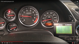
Initially when everything was plugged in, with the headlights off, the odometer looked completely dark.(I soon noticed the segment display was Very dimly lit leading me to think it could simply be the backlight) I think you can see this clearly near the end of the included video.
Checked the backlight screw in bulb, and it was not illuminating. Swapped the bulb to a known working one, and with the lights on, it illuminates the backlight bulb. (great I can see my odometer at night)
The first photo was to show I could see the odometer in bright daylight before, and specifically without the backlight, the second photo to show I could see it with the backlight to prove the segment display was operational.
I neglected to show evidence that the odometer did not show the segment display while lights were off.
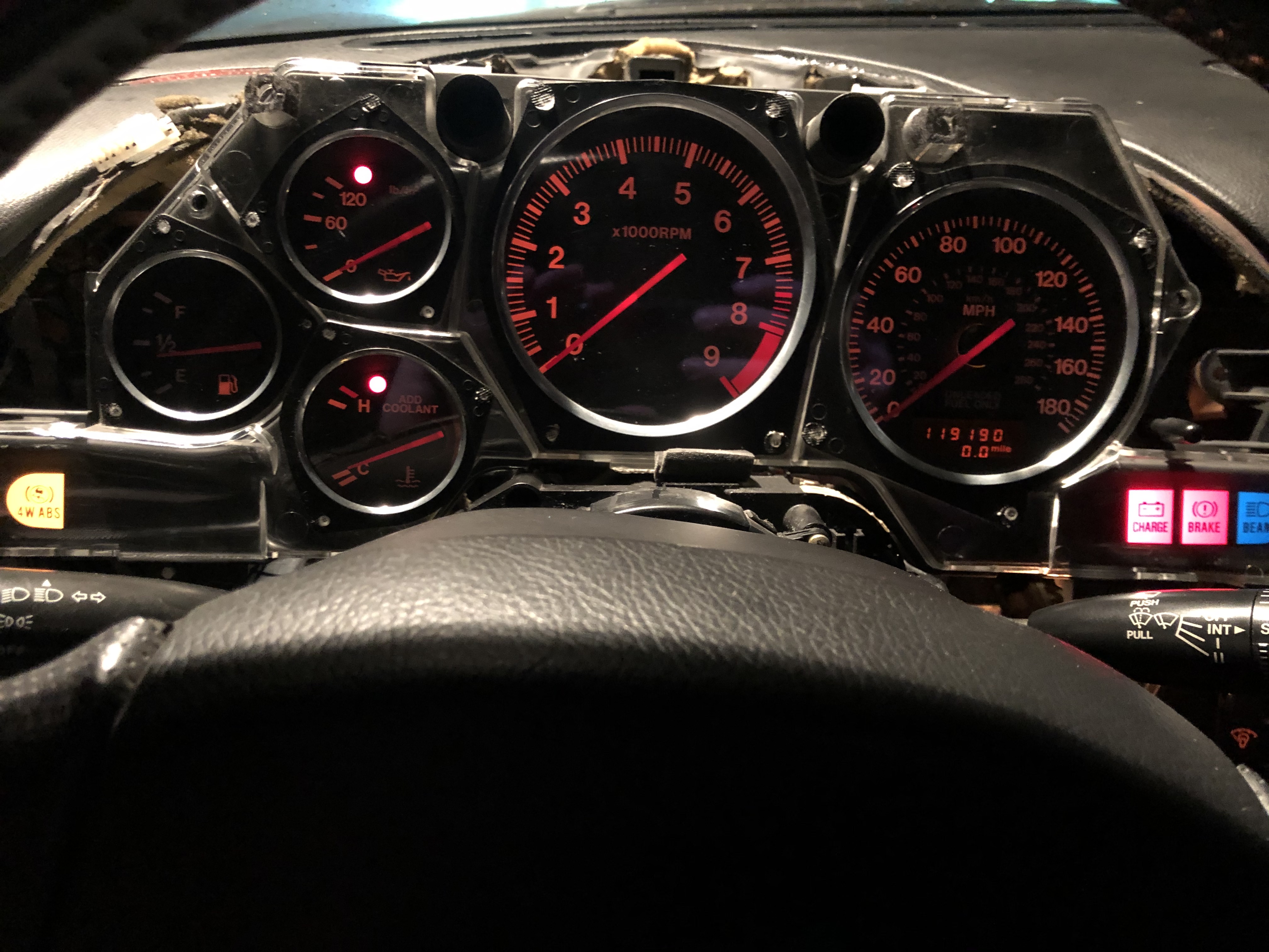
This is what the cluster looked like when started, and light switch off
You can just barely make out the illuminated segments, under what I believe should be a high power mode for the segments (while the lights are off)
Something has changed though, because I believe the segments are "high power" illuminating normally now with no changes. Perhaps a capacitor needed time to charge?
I cleaned all the bulb contacts and wiped all the bulb lenses clean, and I believe the cluster is now currently working as expected. Even the "bad bulb" once the spring contactors were sprung back out.
Any thoughts on why there was a delay in the normal "bright illumination" of the segmented display, why would it take so long to become active?
Unfortunately I have disconnected the cruise control (space limitations), but if it would help validate, I could reconnect it. As far as I can tell Normal operation has been restored fully, the needle does not hunt at all, very linear and fluid for both RPM and Velocity as well as very stable at a steady state.
Any preventative maintenance in the cluster area I can plan to do before reassembly becomes the next step?
Believe me, you have been a bigger help than you realize, that is my main roadblock, information and guiding experience.
I feel I can do almost anything if I have a confident experienced hand to guide the Correct way forward.
Last edited by rotarypower101; Feb 29, 2020 at 05:41 PM.
You are very welcome! I'm glad to help. That is why I curate the speedo threads - to unlock its many mysteries and help other members who are willing to give it a shot.
I account capacitor charge times for the dim/no LCD illumination problem. Now, which capacitor controls that - well, that's something I haven't figured out yet.
If you choose to reconnect your cruise control then that's up to you. Based upon your initial video, description, and photos, I'd say you did an excellent job at fixing your speedo and over-rev buzzer alarm!
I also wish to point out that your odometer still recorded mileage between the before and after photos. The odo was 119,183 in the first picture then it read 119,190 in the second picture. You did see the odo and tripometer move after those photos were taken, right?
As I stated before, don't disconnect the battery from the car and put a few miles on it during this coming week. You want to see how it reacts under normal driving conditions. Give the electronics some time to adjust to the new tolerances of brand new components. Take this analogy - you just replaced older vital organs with new ones. You need to verify the body will adjust to the new organs.
In the meantime, you could investigate that pesky low oil level light. Otherwise, button it up, have a cigar, and a bourbon and coke!
For completeness here is a quick video showing its, I think, fully corrected operation.
How long would you advise to monitor the cluster disassembled ? Rough amount of miles and hours of run time?
If you will notice, I did solve the oil level light. There seems to be something not right with the duplicated (I have 2 stock level sensors tied into the same oil level warning system) auxiliary oil level sensor I am using for my 2 stroke oil reserve. my assumption is that it is jammed open, but it is a bit of a chore to dig into without some other associated task... So I simply unplugged it and labeled the plug with a note to check and repair/replace whatever the issue might be.
Thanks for sharing the brief video. Good job on the oil level light. It looks like you have a fully working instrument cluster now. I noted your tripometer works. I didn't see the odo increment but I can infer that it works from your previous photos.
You could reassemble the cluster to the hood then reinstall. You could monitor it until you feel confident that it will not cause any problems. There is no hard or fast time/mileage to monitor it. As an example, I'm on an "extended test cycle" for my odo! That may be my superstition because if I call it "fixed" then that's when it will fail.
You could reassemble the cluster to the hood then reinstall. You could monitor it until you feel confident that it will not cause any problems. There is no hard or fast time/mileage to monitor it. As an example, I'm on an "extended test cycle" for my odo! That may be my superstition because if I call it "fixed" then that's when it will fail.

Thread
Thread Starter
Forum
Replies
Last Post