93 FD3S Auto to Manual swap, step by step.
 01-30-13, 06:20 PM
#26
20B/5 Speed/JC!
iTrader: (2)

Join Date: Jul 2007
Location: Sahuarita, AZ
Posts: 406
Likes: 0
Received 0 Likes
on
0 Posts
If you don't care to have your nuetrel safety switch working, which I didn't, you really only have to make 2 seperate splices. That's if you're planning to keep your stock auto harnesses.
I don't have the pictures on me now since I'm at work, but the FSM will. But essentially you only need to concern yourself with the biggest connecter coming from the engine bay area, your starter wire should be plug and play.
For the big connector, if you take a look you will notice 2 wires are noticeably bigger than the others. IIRC, they are both on the bottom row on opposite corners of the plug. Splice those 2 together.
Now for you reverse lights, you'll be concentrating on the 2 wires on the top row, all the way to the right. I think they are brown, and brown/black. When you're looking at the connector make sure the clip part is on top. Those 2 wires you will need to dyke and splice into your factory reverse sensor coming from the trans, there will be 2 wires. It doesn't matter which wire splices into which, as long both wires have a partner.
 01-31-13, 04:51 AM
#27
thanks a ton , thats pretty much exactly what i needed to know
If you don't care to have your nuetrel safety switch working, which I didn't, you really only have to make 2 seperate splices. That's if you're planning to keep your stock auto harnesses.
I don't have the pictures on me now since I'm at work, but the FSM will. But essentially you only need to concern yourself with the biggest connecter coming from the engine bay area, your starter wire should be plug and play.
For the big connector, if you take a look you will notice 2 wires are noticeably bigger than the others. IIRC, they are both on the bottom row on opposite corners of the plug. Splice those 2 together.
Now for you reverse lights, you'll be concentrating on the 2 wires on the top row, all the way to the right. I think they are brown, and brown/black. When you're looking at the connector make sure the clip part is on top. Those 2 wires you will need to dyke and splice into your factory reverse sensor coming from the trans, there will be 2 wires. It doesn't matter which wire splices into which, as long both wires have a partner.
I don't have the pictures on me now since I'm at work, but the FSM will. But essentially you only need to concern yourself with the biggest connecter coming from the engine bay area, your starter wire should be plug and play.
For the big connector, if you take a look you will notice 2 wires are noticeably bigger than the others. IIRC, they are both on the bottom row on opposite corners of the plug. Splice those 2 together.
Now for you reverse lights, you'll be concentrating on the 2 wires on the top row, all the way to the right. I think they are brown, and brown/black. When you're looking at the connector make sure the clip part is on top. Those 2 wires you will need to dyke and splice into your factory reverse sensor coming from the trans, there will be 2 wires. It doesn't matter which wire splices into which, as long both wires have a partner.
01-31-13, 06:14 PM
#28
20B/5 Speed/JC!
iTrader: (2)
Join Date: Jul 2007
Location: Sahuarita, AZ
Posts: 406
Likes: 0
Received 0 Likes
on
0 Posts
No problem!
I would seriously consider doing this swap again in the States since auto's are metric crap ton cheaper than 5 speeds, and often less abused.
IMO I think the hardest thing about the whole swap was locating all the parts needed.
I would seriously consider doing this swap again in the States since auto's are metric crap ton cheaper than 5 speeds, and often less abused.
IMO I think the hardest thing about the whole swap was locating all the parts needed.
01-31-13, 07:33 PM
#29
thats exactly why i bought mine, that and it is RHD , the car had been babied since day one and was in top notch shape internally and externally , with the entire swap my only concerns were to do with the wiring , but next winter ill be pulling out the hole dash and the harness/ cluster and swapping everything out for manual ! lol i should really of made a build thread , oh well
02-05-13, 05:00 AM
#31
20B/5 Speed/JC!
iTrader: (2)
Join Date: Jul 2007
Location: Sahuarita, AZ
Posts: 406
Likes: 0
Received 0 Likes
on
0 Posts
It's fairly useless, unless you change the fittings to the ones your engine oil cooler uses since they're different fittings, same type cores. I think ultimately it may be easier to just source a stock dual oil cooler set up with the associated lines, I did that with mine.
02-07-13, 06:10 AM
#32
ok! ill be doing that then! , thanks for the help
It's fairly useless, unless you change the fittings to the ones your engine oil cooler uses since they're different fittings, same type cores. I think ultimately it may be easier to just source a stock dual oil cooler set up with the associated lines, I did that with mine.
02-09-13, 02:21 AM
#33
Junior Member

Join Date: Mar 2006
Location: Key West, FL
Posts: 39
Likes: 0
Received 0 Likes
on
0 Posts
Hello,
I'm in the middle of my auto to manual swap. I've read all of the threads. I have two questions that were not addressed. The electrical question may have been addressed with pics about 8 years ago, but the hyperlinks are all dead at this time.
I plan on redoing the step by step list when I'm completely done to include the questions that I've run into that I didn't see answers to.
So, here are my 2 questions:
Background: I have a 1994 RX7 FD3 automatic. All of the harnesses are automatic.
I've removed everything for the tranny swap and I am waiting on a few parts to arrive.
2 questions:
#1 Question - Electrical:
There are approximately 5 electrical connector plugs on the autotranny and the same number on the car. My new manual tranny has 4 connectors and the majority have different plugs.
Do I need to connect all of the automatic plugs on the car's harness to the manual tranny connectors?
-If not, which ones will not need to be connected.
-If I do not need to connect some of the plugs, is it necessary to ground the unused plugs?
Any recommendations on connecting the nuetral switch and the clutch switch to the clutch pedal assembly?
#2 QUESTION - AT oil cooler:
-I have removed all of the AT cooler system. (AT cooler, all AT hoses)
I now have two nipples with no hose connected to them on the lower side of the radiator. The nipples were connected to the AT oil cooler hoses. Do I need to cap them or can I just leave them? I notice that there is a hose connecting the radiator to the air/water separator. If I leave the nipples un capped, will this cause any troubles with the air/water separation?
I'm following up the my question above for future AT to MT transmission swappers.
**Thank you to those that have helped out.
Here is some helpful info. I'm taking the info directly from the FD shop manual (page Z-72, Z-34, ) and cross referencing it with the connections that I've just completed and tested on my car after the swap.
The auto harness on your car will have the following connectors:
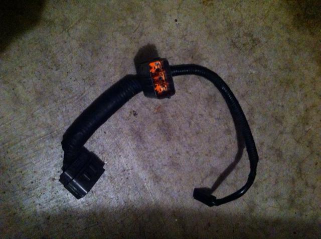
1) Park / Neutral Switch (large grey 9 pin connector with an orange center) (You'll modify this connector during the swap.
2) Vehicle Speed Pulse Generator (black rectangular connector with a yellow center) This looks like it has 4 medium sized pins and 2 tiny pins. The connector only actually uses 3 of these pins and it'll have 3 wires going to it. (This is a direct plug and play for your MT tranny and this provides info to your speedometer)
3) Vehicle Speed Sensor: Black flat 3 prong connector ( you won't use this, tape the end up with electrical tape and zip tie it out of the way.
4) Selenoid Valve (EC-AT) connector: Black 8 pin connector with yellow center (you will not use this)
On the new MT transmission you should have the following sensors/connectors:
A) Neutral Switch (2 wires) (not used)
B) 1-2 Switch (4 wires) (not used)
C) Reverse sensor: black female 2 pin connector with yellow center and 2 green wires (needs to me modified: see below)
D) Speed Sensor (Directly connects to AT harness on car)
** If your MT Tranny doesn't have the 1-2 switch or neutral switch, that's ok as long as the holes are plugged.
To connect the MT tranny to the AT harness:
1) Connect black speedometer connector (plug and play). #2 above on the AT harness to #D above on the MT tranny. Speedometer sensor is on right side of MT tranny and the sensor looks like a black cylinder that is approx 2" long.
2) Modify the reverse sensor #C above on the MT tranny and connect it #1 above ( park / neutral switch) on the AT harness. (This will make your back up lights work and make the "R" on your dash light up when in reverse.
Recommendation: Cut the black plug off of the end of the reverse sensor #C. Install a 1/4" male spade connector to the end of each green wire from #C.
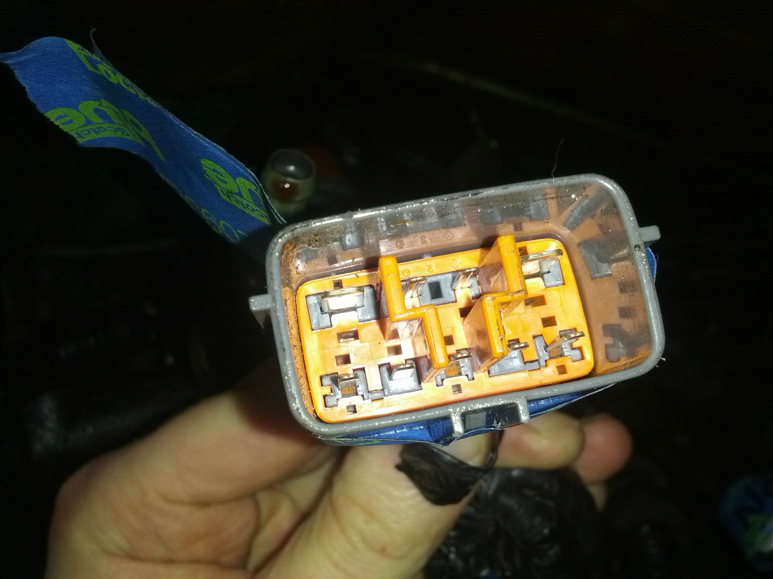
Cut the wires from the 2 and 7 (page k-28 of manual) pins on the Park/Neutral Switch (#1 above). Pin 2 is a Brown with a black stripe and pin 7 is yellow with a blue stripe.
[If the colors don't match, then when you're looking at the plug from the end of the plug and the two large connectors are on the bottom, then you need the top right two wires.
Connect a 1/4" female spade connector to the end of each of the two wires.
3) Starter Interlock switch connection or jumper. There are two options here
Option A) This setup will be like a stock FD and you will be required to depress the clutch pedal to start the car.
-This option requires you to have a starter interlock switch mounted on your clutch pedal assembly. The starter interlock switch is a white rectangular looking box with a plunger and a short black wire coming off of it. The interlock switch is mounted on the left upper side of the clutch pedal assembly.
-Run two 12 gauge wires from the clutch pedal assembly area up into the dash above the pedal, under the radio section of your vehicle and down through the stick shift hole down to the transmission. I put the wire inside 1/4" or 3/8" wire loom to protect it.
Note: you need approximately 5-6' of wire x 2
-Connect an insulated Female 12 gauge 1/4" spade connector (yellow colored) to both ends of both wires. (Note: its important to use the right sized wire and connectors for this to ensure that you get enough juice through this circuit and back to your starter to start the vehicle.)
-Plug two connectors into the pale spade connectors on the starter interlock switch. Plug the other end of the cables into the # 8 and #9 pins on the Park / neutral connector (#1 above). These are the largest pins on the large grey connector with an orange center. The pins are interchangeable because order doesn't matter for this.
Option B) Jumper the park / neutral switch (#1 above) at the connector. This option does not require you to depress the clutch pedal to start the car, but if you have the car in gear and you turn the key, the car will lurch forward if the clutch isn't depressed.
-Cut 3" of 12 gauge wire. Connect an insulated 1/4" female spade connector (yellow colored) to each end of the wire. Plug the ends of the jumper into the #8 and #9 pin on the Park/neutral switch plug (#1 above). Again, these are the large pins in the connector.
I hope that this helps.
Chips
02-09-13, 02:27 AM
#34
Junior Member
Join Date: Mar 2006
Location: Key West, FL
Posts: 39
Likes: 0
Received 0 Likes
on
0 Posts
Ok, I've connected my main wires, installed my tranny, test driven it and everything works.
I have the 2 more electrical questions to complete this swap fully.
1) How do I get the "hold" light to stop flashing.
-I've been reading the electrical diagrams and I am planning on jumpering the unused "hold" light connector by the stick shift, cutting a wire that goes to the "hold" lamp in the dash or ?????
02-09-13, 02:44 AM
#36
Junior Member
Join Date: Mar 2006
Location: Key West, FL
Posts: 39
Likes: 0
Received 0 Likes
on
0 Posts
Continuing on:
Any recommendations on the "hold" light issue?
2) I want to connect the clutch switch on the clutch pedal assembly. I've read that by connecting this the ECU will know when the clutch is depressed and it will increase the idle speed to prevent the car from dying at stop lights when the A/C is on. I've also read that depressing the clutch will also disengage the cruise control.
- I've reviewed the wiring diagrams (pages Z-26, Z-34, Z-108) in the 1994 FD shop manual and I believe that I have to do the following, but I want to verify this with someone before I start tapping / cutting wires.
-It looks like I need to make a "Y" shaped cable with 3 legs. The first leg should run to Pin G on the cruise control , the 2nd leg should run to Pin "1Q" on the ECU and the third leg should go to a terminal on the clutch switch (mounted on the clutch pedal assembly).
-A second wire should be run from ground to the second terminal on the clutch switch.
Then, when you depress the clutch pedal, this grounds the connection and sends a signal to both the ECU and the cruise control computer.
***This is how I read the wiring diagram, but one previous user said connect pin "1Q" on the ECU to the clutch switch and the other wire to a continuous 12 v source.
***A second user said to connect Pin G on the cruise control to the clutch switch.
***I'm getting conflicting info. Can anybody provide some clarity?
Thanks again!
02-09-13, 02:49 AM
#37
Junior Member
Join Date: Mar 2006
Location: Key West, FL
Posts: 39
Likes: 0
Received 0 Likes
on
0 Posts
Thanks for your reply. I"m going to try to figure it out first with my AT cluster and if that doesnt' work I'll look for a MT cluster
thanks!
02-09-13, 03:22 AM
#38
20B/5 Speed/JC!
iTrader: (2)
Join Date: Jul 2007
Location: Sahuarita, AZ
Posts: 406
Likes: 0
Received 0 Likes
on
0 Posts
No worries man, what you're doing now is going to be of great help to someone in the future. Unfortunately I can only answer so much because I didn't want the neutral safety switch, I didn't have cruise control from the factory, I switched tach's, and I went with a Power FC.
04-21-13, 11:30 AM
#39
I'm following up the my question above for future AT to MT transmission swappers.
**Thank you to those that have helped out.
Here is some helpful info. I'm taking the info directly from the FD shop manual (page Z-72, Z-34, ) and cross referencing it with the connections that I've just completed and tested on my car after the swap.
The auto harness on your car will have the following connectors:
1) Park / Neutral Switch (large grey 9 pin connector with an orange center) (You'll modify this connector during the swap.
2) Vehicle Speed Pulse Generator (black rectangular connector with a yellow center) This looks like it has 4 medium sized pins and 2 tiny pins. The connector only actually uses 3 of these pins and it'll have 3 wires going to it. (This is a direct plug and play for your MT tranny and this provides info to your speedometer)
3) Vehicle Speed Sensor: Black flat 3 prong connector ( you won't use this, tape the end up with electrical tape and zip tie it out of the way.
4) Selenoid Valve (EC-AT) connector: Black 8 pin connector with yellow center (you will not use this)
On the new MT transmission you should have the following sensors/connectors:
A) Neutral Switch (2 wires) (not used)
B) 1-2 Switch (4 wires) (not used)
C) Reverse sensor: black female 2 pin connector with yellow center and 2 green wires (needs to me modified: see below)
D) Speed Sensor (Directly connects to AT harness on car)
** If your MT Tranny doesn't have the 1-2 switch or neutral switch, that's ok as long as the holes are plugged.
To connect the MT tranny to the AT harness:
1) Connect black speedometer connector (plug and play). #2 above on the AT harness to #D above on the MT tranny. Speedometer sensor is on right side of MT tranny and the sensor looks like a black cylinder that is approx 2" long.
2) Modify the reverse sensor #C above on the MT tranny and connect it #1 above ( park / neutral switch) on the AT harness. (This will make your back up lights work and make the "R" on your dash light up when in reverse.
Recommendation: Cut the black plug off of the end of the reverse sensor #C. Install a 1/4" male spade connector to the end of each green wire from #C.
Cut the wires from the 2 and 7 (page k-28 of manual) pins on the Park/Neutral Switch (#1 above). Pin 2 is a Brown with a black stripe and pin 7 is yellow with a blue stripe.
[If the colors don't match, then when you're looking at the plug from the end of the plug and the two large connectors are on the bottom, then you need the top right two wires.
Connect a 1/4" female spade connector to the end of each of the two wires.
3) Starter Interlock switch connection or jumper. There are two options here
Option A) This setup will be like a stock FD and you will be required to depress the clutch pedal to start the car.
-This option requires you to have a starter interlock switch mounted on your clutch pedal assembly. The starter interlock switch is a white rectangular looking box with a plunger and a short black wire coming off of it. The interlock switch is mounted on the left upper side of the clutch pedal assembly.
-Run two 12 gauge wires from the clutch pedal assembly area up into the dash above the pedal, under the radio section of your vehicle and down through the stick shift hole down to the transmission. I put the wire inside 1/4" or 3/8" wire loom to protect it.
Note: you need approximately 5-6' of wire x 2
-Connect an insulated Female 12 gauge 1/4" spade connector (yellow colored) to both ends of both wires. (Note: its important to use the right sized wire and connectors for this to ensure that you get enough juice through this circuit and back to your starter to start the vehicle.)
-Plug two connectors into the pale spade connectors on the starter interlock switch. Plug the other end of the cables into the # 8 and #9 pins on the Park / neutral connector (#1 above). These are the largest pins on the large grey connector with an orange center. The pins are interchangeable because order doesn't matter for this.
Option B) Jumper the park / neutral switch (#1 above) at the connector. This option does not require you to depress the clutch pedal to start the car, but if you have the car in gear and you turn the key, the car will lurch forward if the clutch isn't depressed.
-Cut 3" of 12 gauge wire. Connect an insulated 1/4" female spade connector (yellow colored) to each end of the wire. Plug the ends of the jumper into the #8 and #9 pin on the Park/neutral switch plug (#1 above). Again, these are the large pins in the connector.
I hope that this helps.
Chips
So do I just go with the pinout and ignore the colors?
04-23-13, 06:02 AM
#40
Junior Member
Join Date: Mar 2006
Location: Key West, FL
Posts: 39
Likes: 0
Received 0 Likes
on
0 Posts
Simply put (referring to the big grey plug) just use the two biggest wires. Regardless of color.
It'll be obvious, because 2 wires are much larger than the rest.
If You get stuck, PM me with your email I'll send you some pictures that I took when I did my swap
It'll be obvious, because 2 wires are much larger than the rest.
If You get stuck, PM me with your email I'll send you some pictures that I took when I did my swap
04-23-13, 06:12 AM
#41
Junior Member
Join Date: Mar 2006
Location: Key West, FL
Posts: 39
Likes: 0
Received 0 Likes
on
0 Posts
Here's some more info for your project.
To get rid of the flashing hold light you'll have to access the main CPU by the passengers foot area. It's a 8" x 8" x 1" metal box (silver colored). Attached to that box are 2 smaller boxes. One is silver and one is black. Disconnect and remove both. You don't need either and disconnecting them will get rid of the flashing light.
To get rid of the flashing hold light you'll have to access the main CPU by the passengers foot area. It's a 8" x 8" x 1" metal box (silver colored). Attached to that box are 2 smaller boxes. One is silver and one is black. Disconnect and remove both. You don't need either and disconnecting them will get rid of the flashing light.
04-23-13, 06:15 AM
#42
Junior Member
Join Date: Mar 2006
Location: Key West, FL
Posts: 39
Likes: 0
Received 0 Likes
on
0 Posts
I also kept my AT dash cluster. The only difference is that your tach will show a red line at 7000 RPMs (automatic) but you can actually go up to 8000 for your redline. Everything works correctly, you just have to remember that you can safely go up to 8000 RPMs.
05-22-13, 11:11 PM
#44
hi there
im about to dive right into all this this tomorrow for rewiring my auto harness on my new manual tranny , one thing i had to ask is my FD is a rhd one , and my previous one was a manual and i could start it with out pushing the clutch in , so i take it i dont have a neutral safety switch? and just curious with just the starter wired in and nothing else would the car start and run? you just would not have any reverse lights or speed censors or anything
if you have some pictures on hand ,my email is s.roland@live.ca if you could send some my way i would really appreciate it
thanks and take care for now
I'm following up the my question above for future AT to MT transmission swappers.
**Thank you to those that have helped out.
Here is some helpful info. I'm taking the info directly from the FD shop manual (page Z-72, Z-34, ) and cross referencing it with the connections that I've just completed and tested on my car after the swap.
The auto harness on your car will have the following connectors:
1) Park / Neutral Switch (large grey 9 pin connector with an orange center) (You'll modify this connector during the swap.
2) Vehicle Speed Pulse Generator (black rectangular connector with a yellow center) This looks like it has 4 medium sized pins and 2 tiny pins. The connector only actually uses 3 of these pins and it'll have 3 wires going to it. (This is a direct plug and play for your MT tranny and this provides info to your speedometer)
3) Vehicle Speed Sensor: Black flat 3 prong connector ( you won't use this, tape the end up with electrical tape and zip tie it out of the way.
4) Selenoid Valve (EC-AT) connector: Black 8 pin connector with yellow center (you will not use this)
On the new MT transmission you should have the following sensors/connectors:
A) Neutral Switch (2 wires) (not used)
B) 1-2 Switch (4 wires) (not used)
C) Reverse sensor: black female 2 pin connector with yellow center and 2 green wires (needs to me modified: see below)
D) Speed Sensor (Directly connects to AT harness on car)
** If your MT Tranny doesn't have the 1-2 switch or neutral switch, that's ok as long as the holes are plugged.
To connect the MT tranny to the AT harness:
1) Connect black speedometer connector (plug and play). #2 above on the AT harness to #D above on the MT tranny. Speedometer sensor is on right side of MT tranny and the sensor looks like a black cylinder that is approx 2" long.
2) Modify the reverse sensor #C above on the MT tranny and connect it #1 above ( park / neutral switch) on the AT harness. (This will make your back up lights work and make the "R" on your dash light up when in reverse.
Recommendation: Cut the black plug off of the end of the reverse sensor #C. Install a 1/4" male spade connector to the end of each green wire from #C.
Cut the wires from the 2 and 7 (page k-28 of manual) pins on the Park/Neutral Switch (#1 above). Pin 2 is a Brown with a black stripe and pin 7 is yellow with a blue stripe.
[If the colors don't match, then when you're looking at the plug from the end of the plug and the two large connectors are on the bottom, then you need the top right two wires.
Connect a 1/4" female spade connector to the end of each of the two wires.
3) Starter Interlock switch connection or jumper. There are two options here
Option A) This setup will be like a stock FD and you will be required to depress the clutch pedal to start the car.
-This option requires you to have a starter interlock switch mounted on your clutch pedal assembly. The starter interlock switch is a white rectangular looking box with a plunger and a short black wire coming off of it. The interlock switch is mounted on the left upper side of the clutch pedal assembly.
-Run two 12 gauge wires from the clutch pedal assembly area up into the dash above the pedal, under the radio section of your vehicle and down through the stick shift hole down to the transmission. I put the wire inside 1/4" or 3/8" wire loom to protect it.
Note: you need approximately 5-6' of wire x 2
-Connect an insulated Female 12 gauge 1/4" spade connector (yellow colored) to both ends of both wires. (Note: its important to use the right sized wire and connectors for this to ensure that you get enough juice through this circuit and back to your starter to start the vehicle.)
-Plug two connectors into the pale spade connectors on the starter interlock switch. Plug the other end of the cables into the # 8 and #9 pins on the Park / neutral connector (#1 above). These are the largest pins on the large grey connector with an orange center. The pins are interchangeable because order doesn't matter for this.
Option B) Jumper the park / neutral switch (#1 above) at the connector. This option does not require you to depress the clutch pedal to start the car, but if you have the car in gear and you turn the key, the car will lurch forward if the clutch isn't depressed.
-Cut 3" of 12 gauge wire. Connect an insulated 1/4" female spade connector (yellow colored) to each end of the wire. Plug the ends of the jumper into the #8 and #9 pin on the Park/neutral switch plug (#1 above). Again, these are the large pins in the connector.
I hope that this helps.
Chips
**Thank you to those that have helped out.
Here is some helpful info. I'm taking the info directly from the FD shop manual (page Z-72, Z-34, ) and cross referencing it with the connections that I've just completed and tested on my car after the swap.
The auto harness on your car will have the following connectors:
1) Park / Neutral Switch (large grey 9 pin connector with an orange center) (You'll modify this connector during the swap.
2) Vehicle Speed Pulse Generator (black rectangular connector with a yellow center) This looks like it has 4 medium sized pins and 2 tiny pins. The connector only actually uses 3 of these pins and it'll have 3 wires going to it. (This is a direct plug and play for your MT tranny and this provides info to your speedometer)
3) Vehicle Speed Sensor: Black flat 3 prong connector ( you won't use this, tape the end up with electrical tape and zip tie it out of the way.
4) Selenoid Valve (EC-AT) connector: Black 8 pin connector with yellow center (you will not use this)
On the new MT transmission you should have the following sensors/connectors:
A) Neutral Switch (2 wires) (not used)
B) 1-2 Switch (4 wires) (not used)
C) Reverse sensor: black female 2 pin connector with yellow center and 2 green wires (needs to me modified: see below)
D) Speed Sensor (Directly connects to AT harness on car)
** If your MT Tranny doesn't have the 1-2 switch or neutral switch, that's ok as long as the holes are plugged.
To connect the MT tranny to the AT harness:
1) Connect black speedometer connector (plug and play). #2 above on the AT harness to #D above on the MT tranny. Speedometer sensor is on right side of MT tranny and the sensor looks like a black cylinder that is approx 2" long.
2) Modify the reverse sensor #C above on the MT tranny and connect it #1 above ( park / neutral switch) on the AT harness. (This will make your back up lights work and make the "R" on your dash light up when in reverse.
Recommendation: Cut the black plug off of the end of the reverse sensor #C. Install a 1/4" male spade connector to the end of each green wire from #C.
Cut the wires from the 2 and 7 (page k-28 of manual) pins on the Park/Neutral Switch (#1 above). Pin 2 is a Brown with a black stripe and pin 7 is yellow with a blue stripe.
[If the colors don't match, then when you're looking at the plug from the end of the plug and the two large connectors are on the bottom, then you need the top right two wires.
Connect a 1/4" female spade connector to the end of each of the two wires.
3) Starter Interlock switch connection or jumper. There are two options here
Option A) This setup will be like a stock FD and you will be required to depress the clutch pedal to start the car.
-This option requires you to have a starter interlock switch mounted on your clutch pedal assembly. The starter interlock switch is a white rectangular looking box with a plunger and a short black wire coming off of it. The interlock switch is mounted on the left upper side of the clutch pedal assembly.
-Run two 12 gauge wires from the clutch pedal assembly area up into the dash above the pedal, under the radio section of your vehicle and down through the stick shift hole down to the transmission. I put the wire inside 1/4" or 3/8" wire loom to protect it.
Note: you need approximately 5-6' of wire x 2
-Connect an insulated Female 12 gauge 1/4" spade connector (yellow colored) to both ends of both wires. (Note: its important to use the right sized wire and connectors for this to ensure that you get enough juice through this circuit and back to your starter to start the vehicle.)
-Plug two connectors into the pale spade connectors on the starter interlock switch. Plug the other end of the cables into the # 8 and #9 pins on the Park / neutral connector (#1 above). These are the largest pins on the large grey connector with an orange center. The pins are interchangeable because order doesn't matter for this.
Option B) Jumper the park / neutral switch (#1 above) at the connector. This option does not require you to depress the clutch pedal to start the car, but if you have the car in gear and you turn the key, the car will lurch forward if the clutch isn't depressed.
-Cut 3" of 12 gauge wire. Connect an insulated 1/4" female spade connector (yellow colored) to each end of the wire. Plug the ends of the jumper into the #8 and #9 pin on the Park/neutral switch plug (#1 above). Again, these are the large pins in the connector.
I hope that this helps.
Chips
Last edited by scotty R; 05-22-13 at 11:15 PM.
05-23-13, 04:06 PM
#47
OK I went to attempt this step, and got a bit confused. So I'm looking at the plug, and the top 2 on the right are the ones I want. So I look at the colors, and they are not as you described. Oh well....but then I looked on the opposite side (looking at the plug, top left) and those two are brown/black and yellow/blue.
So do I just go with the pinout and ignore the colors?
So do I just go with the pinout and ignore the colors?
Again, the only other wiring change required was to jump the starter with the two big wires, or you can run them up through the cutout to your clutch switch.
Whenever I get time, maybe this long weekend, I'll be going through the steps with my comments for little tricks that made the swap easier for me to do.
05-23-13, 07:20 PM
#48
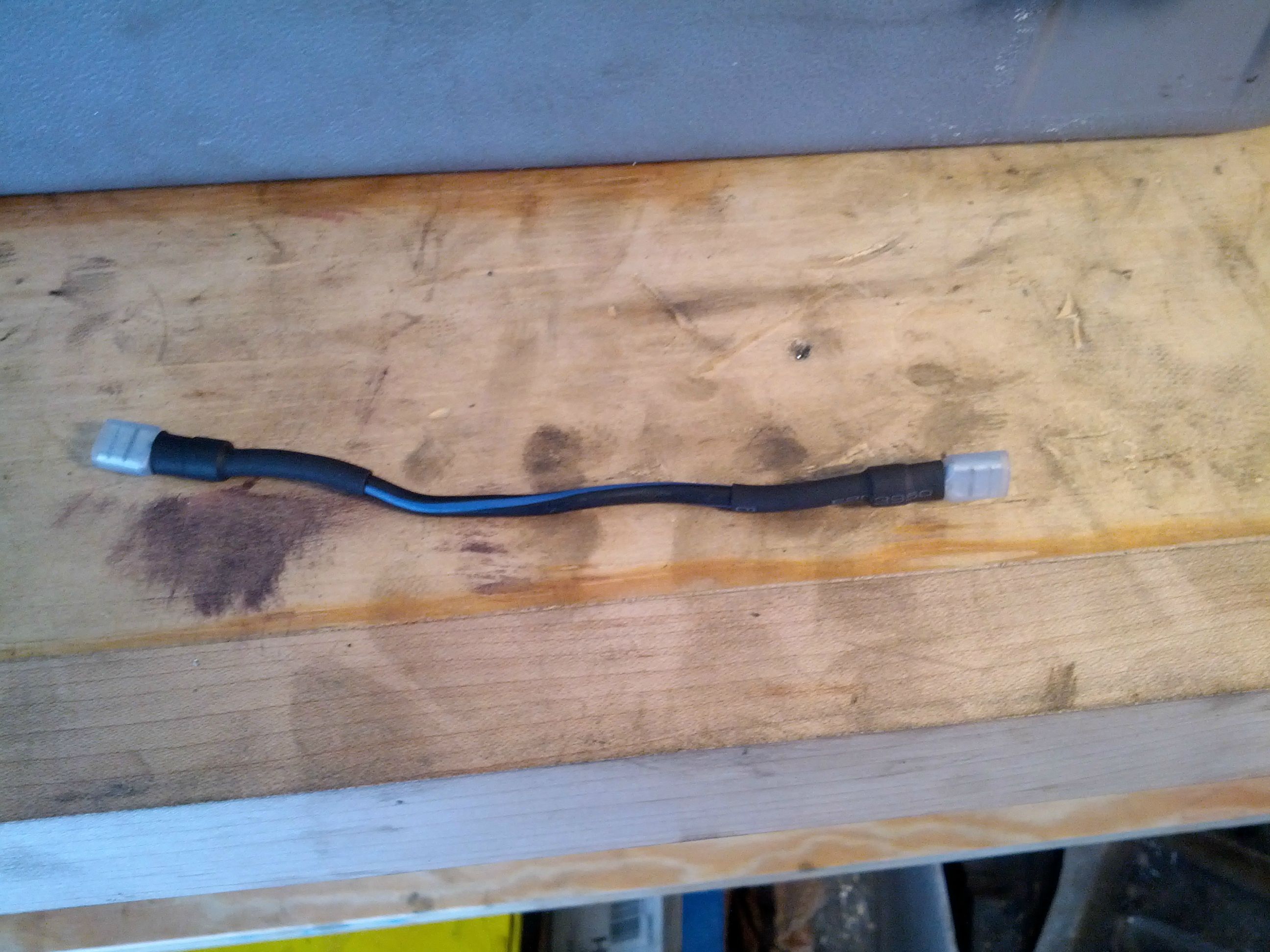
is this the wire you are talking about with the starter to jump it?
also how do you do this and where do you connect it to , i had to buy an aftermarket starter and the only connection was with the ground and single plug, would it make a difference since my car is a RHD model not a US spec one
any help would be great
thanks

also how do you do this and where do you connect it to , i had to buy an aftermarket starter and the only connection was with the ground and single plug, would it make a difference since my car is a RHD model not a US spec one
any help would be great
thanks
Finished my swap a little while ago and am answering my own question for future users. When you look at the plug end (wires coming out the back) and the larger wires are on the bottom, you want the TOP LEFT two wires, which were brown/black and yellow/blue for the reverse lights.
Again, the only other wiring change required was to jump the starter with the two big wires, or you can run them up through the cutout to your clutch switch.
Whenever I get time, maybe this long weekend, I'll be going through the steps with my comments for little tricks that made the swap easier for me to do.
 05-23-13, 10:21 PM
#50
ok , would i go to a auto zone to buy the these plugs and wire ? and does that that hole plug just plug onto the starter after? and is the big connector in your pic the big one coming down from the top on the right or is it the one i posted in my pic and you just split them up and used one connector .
thanks again
thanks again
Last edited by scotty R; 05-23-13 at 10:31 PM.