
2 sensors in back of the coolent filler neck


Thread Starter
Rotary Enthusiast
Joined: Mar 2002
Posts: 1,430
Likes: 0
From: Tuscaloosa, AL
2 sensors in back of the coolent filler neck
There are 2 sensors in the back of the coolent filler neck and I was wondering what they are for , The is also one in the front. Which is which, water temp, water level, fans??

Actually the one in the front is the coolant level sensor, the two in the back are the fan switch(thermoswitch) and the other is the coolant temp sensor for the ecu, not for the gauge. I forget which one is witch.
Originally posted by 93redFD
so do I need to pull one out and re-thread it for a after-market water temp guage?
so do I need to pull one out and re-thread it for a after-market water temp guage?
Thread Starter
Rotary Enthusiast
Joined: Mar 2002
Posts: 1,430
Likes: 0
From: Tuscaloosa, AL
The autometer has a 1/2 inch pipe thread, it will need drilling, nut know biggy. We will be drilling it tomorow, and putting the motor back in the car. I have to get a few other things though(studs,nut, bolts ect..damn engine builder) . The sensor in the back bottom of the water pump housing doesnt have anything to connect to it, will this be ok?
Trending Topics
Originally posted by 93redFD
The autometer has a 1/2 inch pipe thread, it will need drilling, nut know biggy. We will be drilling it tomorow, and putting the motor back in the car. I have to get a few other things though(studs,nut, bolts ect..damn engine builder) . The sensor in the back bottom of the water pump housing doesnt have anything to connect to it, will this be ok?
The autometer has a 1/2 inch pipe thread, it will need drilling, nut know biggy. We will be drilling it tomorow, and putting the motor back in the car. I have to get a few other things though(studs,nut, bolts ect..damn engine builder) . The sensor in the back bottom of the water pump housing doesnt have anything to connect to it, will this be ok?
http://66.216.67.51/product.asp?0=212&1=270&3=390
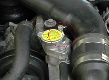
If so, there is no drilling required. You remove the hex bolt on top of the housing and insert there (I installed mine there not too long ago). Here's a pic, but not of mine:
As far as the sensor on the back bottom, that's the switch to turn the fans on. If you have done the fan mod, it's probably not a problem. If you don't have the fan mod, you might want to get that connected.
Thread Starter
Rotary Enthusiast
Joined: Mar 2002
Posts: 1,430
Likes: 0
From: Tuscaloosa, AL
I was told that it was best and most accurate to put the sensor on behind the the thermostat becuase it would only read accurate when the thernostat was open(before the thermostate). any opinions?
Originally posted by 93redFD
I was told that it was best and most accurate to put the sensor on behind the the thermostat becuase it would only read accurate when the thernostat was open(before the thermostate). any opinions?
I was told that it was best and most accurate to put the sensor on behind the the thermostat becuase it would only read accurate when the thernostat was open(before the thermostate). any opinions?
Take a read here:
https://www.rx7club.com/forum/showth...threadid=74058
https://www.rx7club.com/forum/showth...hreadid=179123
A good discussion here:
https://www.rx7club.com/forum/showth...hreadid=187766
Good luck!

ok, i hate to ask a question that you've prob heard a zillion times but i've searched and i havent found the right answer to my problem.. but since this thread is similar, i might as well bring it back from the dead and ask here instead of making another thread.
anyway
i have a nordskog LED digital temp gauge, coming out of the back of the gauge is 4 wires, red, black, purple, and blue..
in the instructions, it said the red is the 12 volts, black is ground, purple is for dim (optional) and blue is to temp sender..
all my understands for these wires are ok except for that blue wire which needs to go to the temp sender..
now this gauge didnt come with any threaded nipple or anything.. now my question(s) are, where would be the best place to put this blue wire and how, should i put it in a new location? how can i connect this thus being only a single wire?
please help
thank you and sorry for the long post and bringing this thread back
PV = nRT
Joined: Jan 2003
Posts: 2,250
Likes: 0
From: New Zealand (was California)
Do not remove that thermosensor. It is used by the ECU.
The single black/red wire one is the thermoswitch used by the fan relays.
There are 3 seperate systems essentially.
1. Control (ECU, fuel injection, etc) sensors.
2. Cooling system/Fan control - the thermo-switch and relays.
3. Warning system (the water temp gauge, located towards the rear of the engine on the left).

Rotary Freak
Joined: Jan 2002
Posts: 2,360
Likes: 0
From: Overland Park, KS
Originally posted by ulost2my7
ok, i hate to ask a question that you've prob heard a zillion times but i've searched and i havent found the right answer to my problem.. but since this thread is similar, i might as well bring it back from the dead and ask here instead of making another thread.
anyway
i have a nordskog LED digital temp gauge, coming out of the back of the gauge is 4 wires, red, black, purple, and blue..
in the instructions, it said the red is the 12 volts, black is ground, purple is for dim (optional) and blue is to temp sender..
all my understands for these wires are ok except for that blue wire which needs to go to the temp sender..
now this gauge didnt come with any threaded nipple or anything.. now my question(s) are, where would be the best place to put this blue wire and how, should i put it in a new location? how can i connect this thus being only a single wire?
please help
thank you and sorry for the long post and bringing this thread back
~Luke
Vagina Junction
Joined: Mar 2001
Posts: 1,838
Likes: 0
From: Seattle, WA
Since the stock guage is virtually useless (even moreso if you're adding an aftermarket guage), I'm recommending pulling the sensor on the block and replacing it with whatever sender your guage comes with. Leave the old one hanging if you want, it'll still move up a little, and your new guage will have the most accurate readout possible.
Last edited by Hyperite; Apr 8, 2004 at 12:51 AM.
Vagina Junction
Joined: Mar 2001
Posts: 1,838
Likes: 0
From: Seattle, WA
Good point, I'll stop suggesting that then.... would the side hex bolt on the housing work? I don't have an airpump, and my sender is too tall to fit under the filler cap with the necessary adapter, but does the side one go into the coolant as well?
Vagina Junction
Joined: Mar 2001
Posts: 1,838
Likes: 0
From: Seattle, WA
Well, the oil filter location is the temperature going into the engine, not out. Also, it's very hard to get out....VERY hard.
I opted for the side hex bolt with some adapters from Home Depot. The sensor isn't directly in the stream of things because of the adapters, but it's very close, and should be as accurate.
I opted for the side hex bolt with some adapters from Home Depot. The sensor isn't directly in the stream of things because of the adapters, but it's very close, and should be as accurate.
Last edited by Hyperite; Apr 9, 2004 at 11:45 PM.
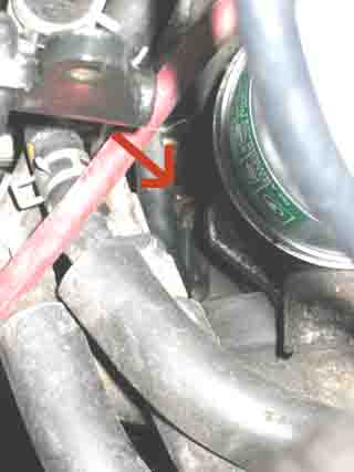
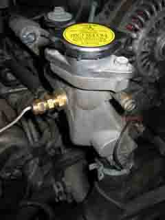
ok guys, i know im a pain in the *** but im doing this job this weekend so let me clear things up
i have the nordskog led digital temp gauge, i bought the sender too so i have everything..
can i place the sender here?
or here?
prob the same thing right? which job is easier?
i have the nordskog led digital temp gauge, i bought the sender too so i have everything..
can i place the sender here?
or here?
prob the same thing right? which job is easier?
PV = nRT
Joined: Jan 2003
Posts: 2,250
Likes: 0
From: New Zealand (was California)