When you click on links to various merchants on this site and make a purchase, this can result in this site earning a commission. Affiliate programs and affiliations include, but are not limited to, the eBay Partner Network.
1994 Airbag Diagnostic Module - System Down Fuse Size Help
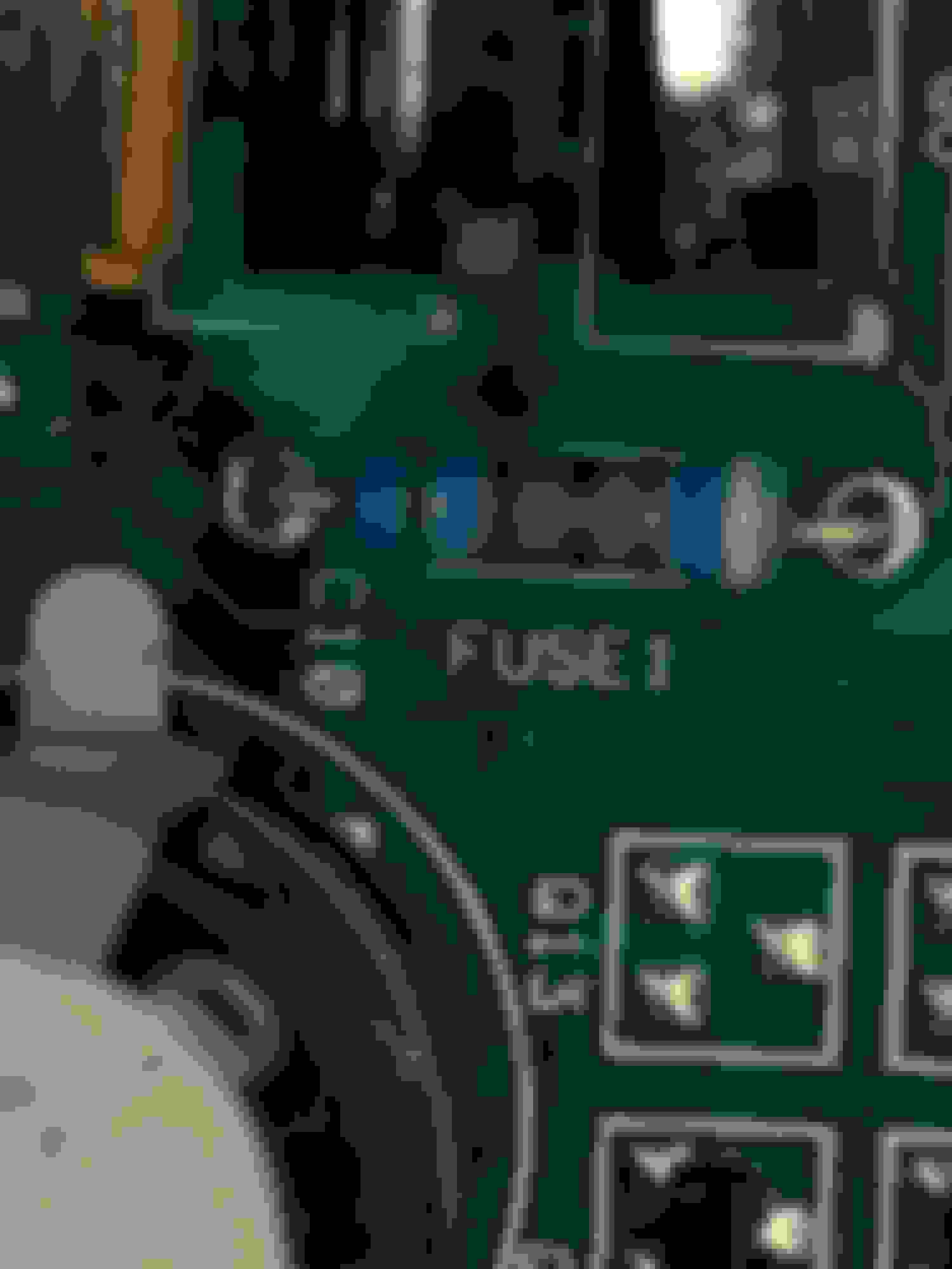
I get the 10 flashes from my airbag light on my 1994 RX-7. I have checked all the sensors per the manual, and replaced all of the capacitors on the airbag diagnostic module. Unfortunately, my system down fuse shows open, and I can�t tell the size of it from the colors. Anyone know more on these than I or have one they could measure?
The middle bands look gold to me, but that doesn�t jive with the resistor color charts. Gold can only be a tolerance or multiplier.
Not sure where to go next!
Just to add. This all started after hooking up the battery after a few months of sitting. This module and the security alarm board but the dust when I reconnected the battery. Old capacitors!
Fusible resistors normally use standard resistor color codes, but when this one failed the heat may have altered the colors a bit. In any case, the color bands will not tell you the fuse's value, just the resistance. Can you post a better picture?
From left to right:
1. Green = first significant figure is 5
2. ? = second significant figure is ?
3. Gold = multiplier 0.1
4. Gold = tolerance =+/- 5%
5: white = fusible
My best guess is that band 2 is blue = 6, so the component's resistance value is 5.6 Ohms +/- 5%. This is a "preferred" or standard (E24) resistor value. If band 2 is any of the other 9 colors, the resistor would have a non-standard value, which certainly is possible but not likely. Sorry I can't help you with the fuse's value. (Fuse values of 6 Watts and greater are usually printed on the resistor.)
Edit: the more I look at your pictures, the more I question my first guess. The second band may be brown rather than blue, for a 5.1 Ohm resistor. That is also a standard (E24) resistor value.
Last edited by Retserof; Jul 12, 2021 at 10:40 AM.
The author of that thread mistakenly identified the fusible resistor in his 1993 module as "1/4 Watt, 10 Amp". Another poster in that thread tried to correct him and said that "it is a 1/4-watt metal-film 10-ohm resistor, not a "10-amp" resistor." However, the color code for a 10 Ohm resistor is Brown/Black/Black for the first 3 bands, which does not match the bands on the fusible resistor shown in any of the photos. (Or, the 1993 module is not the same as the 1994 module.) He also gave a Digi-Key part number for what is a conventional 10 Ohm resistor, not a fusible resistor.
Last edited by Retserof; Jul 19, 2021 at 05:47 PM.
The pictures in that thread have the resistor that matches what OP has pictures of, but it doesn't have any other information that would be super helpful other than some burned circuit photos.
Since its a fusible resistor the last white band is just the fusible indicator. That leaves the remaining 4 bands to indicate the value. The colors I see are
1. Green
2. Brown
3. Gold
4. Gold
Which should come out to 5.1 Ohms 5%. The other thread has a decent res shot of the same resistor is in the other thread and the colors appear match (green, brown, gold, gold) when I zoom and enhance.
The '94s had a passenger airbag not found in the '93 so it would not be a surprise for the board to be different and the fusible resistor of a different value. Although I first thought it might be 5.6 Ohms, I agree that 5.1 Ohms is the correct resistance value, but the important value remains unknown - the fuse rating. All we can say for sure is that it is less than 6 watts, since the rating is not printed on it. Although it would probably work, it would be a mistake use a standard 5.1 Ohm resistor here -- it would be like replacing a fuse with a solid wire, eliminating the protection given by the fuse.
I vaguely recall that metal film fusible resistors are "preferred" when the power rating is 1 watt or less, but I can't think of any way to determine the rating of the OEM fuse without popping one for the fun of it.
Considering how close it is to other PCB components and how much heat fusable resistors can generate right before they pop, it seems like it would have to be on the lower side of less than 6 watts.