When you click on links to various merchants on this site and make a purchase, this can result in this site earning a commission. Affiliate programs and affiliations include, but are not limited to, the eBay Partner Network.
I will say that after seeing the pics and examining what needed to be done for the installation, that I would suggest doing things differently than what he did for connecting to the map wire. The way I will be doing it should make it much easier and it will keep your engine bay from looking sloppy. **This whole post is for Spirit R clusters though as the Mazdaspeed and 99 clusters don't have a boost gauge.**
Instead of going through all the trouble of getting a single wire out to the engine bay, I will be running both the power and ground wires over to the ecm. I will be tapping the same wire that he used in the engine bay but at the ecm instead. I will also be using one of the factory grounds at the ecm as well. This will keep everything nice and tidy.
Here is the wiring diagram which I've highlighted to show what I'm referring to.
Last edited by THE TECH; Sep 22, 2017 at 11:08 AM.
You won't be needing the later wiring diagram, what you need is the one for your car, just attach it to the same map sensor wire in the passenger footwell at the ECU plugs. I did this when I last fitted late clocks in an early car.
You won't be needing the later wiring diagram, what you need is the one for your car, just attach it to the same map sensor wire in the passenger footwell at the ECU plugs. I did this when I last fitted late clocks in an early car.
That's not what we're talking about. I already described above how to wire the map sensor.
So it looks like I might have a bad Spirit R cluster. When I got it and installed it (prior to hooking up the boost gauge) I noticed that not all the backlighting worked on the cluster. I didn't think much of it since I knew I was going to replace all the bulbs with leds so I figured I just had a bad bulb. Well after replacing all the bulbs with leds, the backlighting issue continues. I've tried swapping bulbs, tried swapping bulb holders, even pulled bulbs and holders off another cluster but nothing fixes it. I reinstalled both my Mazdaspeed one and oem one and they both light up perfectly. I don't really know what else to do at this point. I've tried checking continuity on the back of the cluster to as many points as possible and I can't immediately find any issues. I have noticed that there are some pin differences between the MS one and the Spirit one but no one else has brought up backlighting issues when installing these so I have somewhat ruled that out. Any help or insight would be appreciated.
I'd guess the damage is likely on the circuitry on the back. You might have to check continuity point to point for all the lighting until you find the break, then solder a replacement wire in would likely be the easiest long term fix.
I'd guess the damage is likely on the circuitry on the back. You might have to check continuity point to point for all the lighting until you find the break, then solder a replacement wire in would likely be the easiest long term fix.
I'm wondering if anyone who has installed one of these, Spirit R or just another one with the boost gauge, has had any of the same issues or had to do wiring to make it work? Reason why I ask is because when you look at the back of these units and compare the ones with the boost gauge to the one without, the pins for the plugs are not identical.
For instance in the following two plugs. The first one is the Spirit R. The second is the MS. You will notice that, for instance, the bottom right position shows ground on the Spirit R but is showing cruise on the MS one. Obviously, even is this isn't the issue with mine, there is likely another issue this is causing that I'm not aware of yet. I have wondered why my cruise control isn't working and this could be the case.
I've installed a '99 spec cluster on mine. Followed exactly how the write up is wired and my cruise control worked without any additional wiring.
On a side note, I since have installed Haltech ECU with terminated harness and GM 3 bar map sensor.
Has anyone ever figured out how to make the boost gauge work with the GM 3 bar sensor?
Would tapping on the signal wire work? Right now the boost gauge is all the way pegged when key on.
What year is your car? US spec?
My guess is that I just have a bad cluster.
As far as using yours with the GM sensor, the likely issue is that the oem sensor and the GM sensor use two different amounts of voltages to determine boost pressure.
As far as using yours with the gm sensor, the likely issue is that the oem sensor and the gm sensor use two different amounts of voltages to determine boost pressure.
1) On the spirit r cluster, the terminal marked ground is the cruise terminal on the original cluster as best I can see from your pictures. Have you changed the wire at that pin to chassis ground? If not I'm assuming that there is voltage coming into the cluster there and would explain the partial back lighting.
2) On the spirit r cluster, the pin between tam and bm is not used. What does it do on the other cluster?
One other observation: the oil level light is connected to 1A that was connected to the diagnostic module. This makes sense if the oil level light replaces the check engine light.
Vince
Last edited by Project88Turbo; Oct 9, 2017 at 10:01 PM.
1) On the spirit r cluster, the terminal marked ground is the cruise terminal on the original cluster as best I can see from your pictures. Have you changed the wire at that pin to chassis ground? If not I'm assuming that there is voltage coming into the cluster there and would explain the partial back lighting.
2) On the spirit r cluster, the pin between tam and bm is not used. What does it do on the other cluster?
One other observation: the oil level light is connected to 1A that was connected to the diagnostic module. This makes sense if the oil level light replaces the check engine light.
Vince
1) I haven't changed any pins yet as others seemed to have installed these clusters without doing anything and they have worked so I'm hesitant on doing anything like that yet especially when I can't tell if that has anything to do with the illumination issue at all.
2) Here are some more pics of the clusters. The MS ones are first and the Spirit R ones are after.
Last edited by THE TECH; Oct 10, 2017 at 08:47 AM.
Hey Matt
Before you saying anything in public that you have a "bad spirit r cluster", I have gone thru look at all your process and pics you taken and it seem you have fried and damage the circuitry board back. It seem like one of your wires you hook up which have damage it.
Now I'm not happy to see and say this, which you have really ruined one good spirit r cluster.
Not so good at all.
It appears that no matter how many times I tell you this, you aren't listening. THERE WERE NO MODIFICATIONS TO THE CLUSTER WHEN I INSTALLED IT!! THE LIGHTS DID NOT WORK WHEN I RECEIVED IT! THIS IS PRIOR TO ANY WIRES BEING CONNECTED TO IT FOR THE BOOST GAUGE! THE WIRES FOR THE BOOST GAUGE HAVE NOTHING TO DO WITH THE LIGHTING.
Hey Matt
Before you saying anything in public that you have a "bad spirit r cluster", I have gone thru look at all your process and pics you taken and it seem you have fried and damage the circuitry board back. It seem like one of your wires you hook up which have damage it.
Now I'm not happy to see and say this, which you have really ruined one good spirit r cluster.
Not so good at all.
I'll be happy to take the blame when you can explain to everyone here how you know that I "fried and damaged the circuitry board" when I did nothing to it when I first installed it. The wiring was not done until I took it out to replace the bulbs when I assumed it was just a bad bulb.
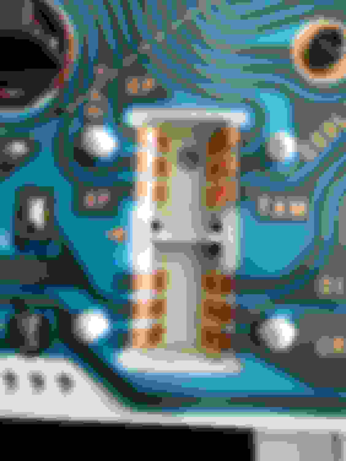
Look at the cluster circuitry back from your pic you taken it have some burn mark to it.
I have look carefully and taken pics of the cluster before I sent it out to you.
It could easily short circuit and damage the cluster when you first plug it in not correctly.
Look at the cluster circuitry back from your pic you taken it have some burn mark to it.
I have look carefully and taken pics of the cluster before I sent it out to you.
It could easily short circuit and damage the cluster when you first plug it in not correctly.


 .
.