When you click on links to various merchants on this site and make a purchase, this can result in this site earning a commission. Affiliate programs and affiliations include, but are not limited to, the eBay Partner Network.
Hi Guy's I just stumbled across this thread and must say I am very impressed with he CAD work on show. I also work in design. mainly for composite tooling so I know exactly what goes into to as I have done a number of parts for my own cars over the years!
I was wondering slightly cheekily if anyone would be willing to share a CAD model of the E-shaft for a 13B engine? I am toying with something in my head but need something to pla with and short of cutting one to pieces a CAD model would be ideal. I would also be interested in housing, irons and rotors if my thought looks like it might work. Just to get things spacially right. What is the deal with the 4 rotor design/build I must find that thread! PM me if you prefer.
I am more than happy to share all the models I have created. Ill throw out the disclaimer that I have told everyone else ive shared with. I made these parts as close as I could using calipers and other tools but there are undoubtedly some errors so dont expect them to be close enough to send to a shop for machining.
That being said, shoot me a PM and I can share all files with you.
Does anyone have files that are pretty close on dimensions? I am looking to build a set for our next project. I have some ideas for doing a set in aluminum using steel inserts on the tips for wear resistance. Thank you.
Good news everyone. I now work at a company that has a FARO arm. Granted, I do not have the experience or skills that 3dmagicmike does but its a start!
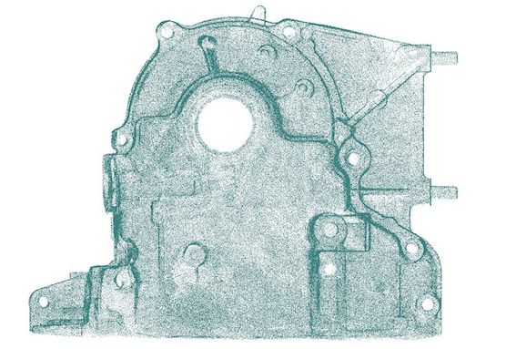
This project hit a brick wall when I finished the "easy" parts and got to parts like the front iron, front cover, water pump etc. I am not sure how long it will take me to make solid models but I am compiling a collection of point clouds of all the engine parts. I will FARO scan the parts I have already modeled as well as other parts. The old parts can be tweaked or remodeled using the scans.
P.S. If anyone has any advise or experience reverse engineering from a point cloud I would love to hear it. The local FARO arm rep things 3dmagicmike is using geomagic software, not sure how much that helps in generating solid models. As far as I know it is still a very manual process and the points are basically for reference only.
Where are you saving all these models? I have a David 3d SLS scanner I could get some point clouds from. I have so of my own models I work from but I only worry about specific items not the whole housing or iron.
I have all the files saved to a google drive. If anyone is interested shoot me a PM. If anyone else is willing to generate point clouds of parts I have yet to scan that would be a HUGE help. Granted we will have to model them after that but its a great starting point!
Awesome thread guys, I have access to an SLM at work (basically a metal printing laser), I regularly prototype in Ti64, Al variants, some Cobalt Chromium and regular steels.
I have always wanted to print then machine to tolerance some Ti housings and rotors, given the mechanical properties I like the potential; at first glance I have concerns around thermal cycling and the apex seals but nothing that can�t be simulated and run with some CFD.
Anyway - my question, how accurate are these drawings? Has anyone machined, tolerances, results?
This is awesome stuff.. Anyone know the exact upper and lower dowel locations relative to the center line of the E-shaft and what the theoretical nominal value of the dowel land bores is supposed to be?