
SPAL FAN-PWN install e-fan controller

Thread Starter
Drive.
Joined: Oct 2002
Posts: 1,676
Likes: 1
From: Washington, North Carolina
SPAL FAN-PWN install e-fan controller
Ok, just got this in this afternoon, and planning on wiring it up tomorrow.
Got a couple questions.
Where are the best places to tap into all of the following locations and if you know it, what are the wire colors for an 88tII?
1) Ignition- can I tap into this under the bay anywhere, or do i need to go through the firewall to the steering column?
2)Air conditioning input (+12v when ignition is on)
3) OEM temp sensor (variable voltage)
What's the best way to test the water temps of my car....according to what I've read...I have to set 2 fan speeds...one for 50% @ "X" temperature and then a second 100% duty @ "X" temperature. What 2 temperatures should I use, and how/where are the best places to check this temperature?
Joined: Feb 2001
Posts: 29,798
Likes: 128
From: London, Ontario, Canada
As the wiring diagrams in the Factory Service Manual will tell you (links to download in the FAQ)...
Black/yellow wire at the leading or trailing coil. But it really depends on where you put the controller. If I'm not mistaken the thick black/white wire at the ignition switch and associated harness is IGN on the inside of the car. Check the manual to be sure.
Magnetic clutch wire.
ECU temp sensor at back of water pump housing. Check the manual for the colours at the ECU or on the harness.
Originally Posted by X-JaVeN-X
1) Ignition- can I tap into this under the bay anywhere, or do i need to go through the firewall to the steering column?
2)Air conditioning input (+12v when ignition is on)
3) OEM temp sensor (variable voltage)
Thread Starter
Drive.
Joined: Oct 2002
Posts: 1,676
Likes: 1
From: Washington, North Carolina
I'm asking because I'm a noob, and these online manuals take FOREVER to try to browse through, and I don't have a hardcopy to look at. Also, the wiring diagrams don't exactly show me where the wires are located in the bay.
Anyway, once all of this is wired up, where is the best place to check temperatures for my hi and low settings? What temps should I shoot for? Where can I pick up a temperature probe at? Autoparts store maybe?
Anyway, once all of this is wired up, where is the best place to check temperatures for my hi and low settings? What temps should I shoot for? Where can I pick up a temperature probe at? Autoparts store maybe?
Joined: Feb 2001
Posts: 29,798
Likes: 128
From: London, Ontario, Canada
The manuals should be downloaded and saved to your computer locally so you can refer to them when you work on the car. The Haynes also has condensed wiring diagrams that are easier to read. Both manuals tell you exactly where the wire is located. After the colour code there is another code in brackets that looks like (F), (EM) etc. That is the harness where the wire is found. F = front (body). EM = emissions (fuel injection), E = engine, etc. This is listed in the FSM.
Most people set the fan to come on around 190 degrees. Then set the high setting to something like 205 or 210. I would assume you will be pulling temp information from the stock ECT that the ECU uses.
Most people set the fan to come on around 190 degrees. Then set the high setting to something like 205 or 210. I would assume you will be pulling temp information from the stock ECT that the ECU uses.
Thread Starter
Drive.
Joined: Oct 2002
Posts: 1,676
Likes: 1
From: Washington, North Carolina
Originally Posted by Aaron Cake
The manuals should be downloaded and saved to your computer locally so you can refer to them when you work on the car. The Haynes also has condensed wiring diagrams that are easier to read. Both manuals tell you exactly where the wire is located. After the colour code there is another code in brackets that looks like (F), (EM) etc. That is the harness where the wire is found. F = front (body). EM = emissions (fuel injection), E = engine, etc. This is listed in the FSM.
Most people set the fan to come on around 190 degrees. Then set the high setting to something like 205 or 210. I would assume you will be pulling temp information from the stock ECT that the ECU uses.
Most people set the fan to come on around 190 degrees. Then set the high setting to something like 205 or 210. I would assume you will be pulling temp information from the stock ECT that the ECU uses.
As far as the "stock ECT that the ECU uses"...what exactly do you mean? Is there a way to check the actual temperatures. I assume where the sensor is a variable voltage...does a certain voltage correspond with a certain temperature?
I need to know the temperature so that I can set the low/high settings for the spal unit, but right now, I have nothing but the stock gauge...which of course doesn't show me a number. How would you suggest checking an accurate temperature?
Joined: Feb 2001
Posts: 29,798
Likes: 128
From: London, Ontario, Canada
Oh, I see what you mean. I'm sure there is a voltage/temperature conversion chart around somewhere for that sensor as it is a standard Bosch sensor but I don't know where that is. Is there a cheap aftermarket temp gauge that you can use? Get a crappy mechanical gauge and temporarily install the sender in the upper rad hose. Really, if you have an e-fan (or are messing with the cooling system in any way) you should already have an aftermarket temp gauge.
Thread Starter
Drive.
Joined: Oct 2002
Posts: 1,676
Likes: 1
From: Washington, North Carolina
Originally Posted by Aaron Cake
Oh, I see what you mean. I'm sure there is a voltage/temperature conversion chart around somewhere for that sensor as it is a standard Bosch sensor but I don't know where that is. Is there a cheap aftermarket temp gauge that you can use? Get a crappy mechanical gauge and temporarily install the sender in the upper rad hose. Really, if you have an e-fan (or are messing with the cooling system in any way) you should already have an aftermarket temp gauge.
I wonder if I can just take like a temperature probe...like you'd use for testing intenal temps of food (i just happen to have one of those for grilling...haha)...and just dip it to get a quick reading.
Trending Topics
I'm a boost creep...
Joined: Jan 2002
Posts: 15,608
Likes: 8
From: Auckland, New Zealand
The S4's linear temp gauge can still be used to set it up, you just have to remember where the gauge normally sits and set the fan to come on when it starts to rise above this. That's the normal way to set up an e-fan.
Thread Starter
Drive.
Joined: Oct 2002
Posts: 1,676
Likes: 1
From: Washington, North Carolina
....I thought about doing it that way...but I had heard the stock gauges weren't that good...or maybe that was just the s5 gauges...I dunno, maybe you can clear that up for me. Crap keeps coming up so I still haven't installed it yet...but I'll be sure to post back when it's done.
I'm a boost creep...
Joined: Jan 2002
Posts: 15,608
Likes: 8
From: Auckland, New Zealand
The S5 temp gauge only has three positions, so it can't be used safely for this. The S4's gauge is linear, so as long as you're familiar with where it normally sits then it can be used. It's no big deal if the temp increases a bit before the fan turns on, as long as the fan stops the temp from increasing further it's doing its job.

Lives on the Forum
Joined: Feb 2001
Posts: 26,664
Likes: 23
From: n
Just tap off the water temp sensor off the side of the engine.
This is the same sensor the gauge uses.
This is the sensor that is right next to the oil pressure sensor.
It doesn't matter how the resistance chart looks, as the FAN-PWM just looks at the resistance (voltage?) of the wire and then triggers how you set it.
-Ted
This is the same sensor the gauge uses.
This is the sensor that is right next to the oil pressure sensor.
It doesn't matter how the resistance chart looks, as the FAN-PWM just looks at the resistance (voltage?) of the wire and then triggers how you set it.
-Ted
Thread Starter
Drive.
Joined: Oct 2002
Posts: 1,676
Likes: 1
From: Washington, North Carolina
Well, it's all wired up except for the actual temperature sensor wire, and the A/C wire.
Ted, I was wondering if I could use that sensor you're talking about. It's just the single wire sensor that's between the oil pedastal and spark plug right?
Do you guys know the color of the wire for the A/C compressor that I need to tap into? I *think* i've found the one I need to tap into...it's black. My a/c needs to be recharged however, so I don't think the compressor is kicking on.
Lives on the Forum
Joined: Feb 2001
Posts: 26,664
Likes: 23
From: n
Originally Posted by X-JaVeN-X
Well, it's all wired up except for the actual temperature sensor wire, and the A/C wire.
Ted, I was wondering if I could use that sensor you're talking about. It's just the single wire sensor that's between the oil pedastal and spark plug right?
Ted, I was wondering if I could use that sensor you're talking about. It's just the single wire sensor that's between the oil pedastal and spark plug right?
It's a single wire.
-Ted
Lives on the Forum
Joined: Feb 2001
Posts: 26,664
Likes: 23
From: n
I just wanted to reply as a follow-up...
My trusty J.C.Whitney electric fan finally kicked the bucket the other week.
Prior to that, for the past month, it was making a rattling noise whenever the FAN-PWM would kick in.
It finally died, and when it did it totally seized.
I was lucky I got the FC parked before the temps got too high (230F according to my water temp gauge).
I got a temporary replacement electric fan, and I was disappointed when I found out the FAN-PWN was not working (no green light) when I plugged in the new fan.
I was kinda pissed I had killed an $80 fan controller, but I can't blame the unit for dying with a seized fan.
I had then remembered the stupid thing was fused, so I checked the fuse.
Lo and behold, the 30A fuse was blown.
I ran out to get some spare 30A fuses, and this fixed everything.
Thank god for fuses, and it looks like the Spal FAN-PWM can withstand an electric fan totally seizing up!
-Ted
Joined: Feb 2001
Posts: 29,798
Likes: 128
From: London, Ontario, Canada
Has anyone else besides RETed and X-JaVeN-X tried this controller and had success/failure?
I'm rather sick of the on/off nature of my electric fan and would like to make it operate more like the stock clutch fan.
I've seen this controller demonstrated at car shows but do not have any first hand experience with it. Reliable?
The wiring in my car is neat and tidy and I'd rather not start tearing it apart to install something else without first hearing if it's actually worth installing.
Lives on the Forum
Joined: Feb 2001
Posts: 26,664
Likes: 23
From: n
Mines is still kicking...even after surviving one dead e-fan.
I'm about to change over from a single 16" puller to the Spal / B-Cool twin 11" pullers soon...
The only other option is that Flex-A-Lite VSC controller...
It uses that blasted push-probe-into-rad-core crap though.
http://www.flex-a-lite.com/auto/html/vsc.html
-Ted
I'm about to change over from a single 16" puller to the Spal / B-Cool twin 11" pullers soon...
The only other option is that Flex-A-Lite VSC controller...
It uses that blasted push-probe-into-rad-core crap though.
http://www.flex-a-lite.com/auto/html/vsc.html
-Ted
Joined: Feb 2001
Posts: 29,798
Likes: 128
From: London, Ontario, Canada
That Flex-A-Lite controller does not look like a very high quality piece. Something that seems to be very common with Flex-A-Lite. No weather tight connectors, crappy probe, plastic case, etc. In other words yuck.
Good to know the SPAL unit is still working. Based on their wiring diagrams it should be easy to add to my car with only the addition of one ground wire in the harness. Of course it still means unlooming the whole damn thing...
Good to know the SPAL unit is still working. Based on their wiring diagrams it should be easy to add to my car with only the addition of one ground wire in the harness. Of course it still means unlooming the whole damn thing...
Joined: Feb 2001
Posts: 29,798
Likes: 128
From: London, Ontario, Canada
Has anyone else had major problems "programming" this controller?
I finally installed mine last weekend but have had no luck making it operate as designed.
I've connected it to the stock ECT sensor and set my high and low points. I've tried several settings for each, but currently they are at 78 and 96/98. The result is the fan seems to run at high speed all the time.
Been talking with a Spal tech these past few days and he's trying to be very helpful. However he's really only given me one suggestion; that my wiring is to blame because of poor grounds. This is not the case.
So does anyone have one working properly using the stock ECT? What are your high and low points?
Ted, I assume you are using a Haltech/GM sensor?
Lives on the Forum
Joined: Feb 2001
Posts: 26,664
Likes: 23
From: n
Mine runs fine...
Actually, I've got mine tapped into a temp sender for my SPI water temp gauge.
The sender doesn't look like anything fancy, but it's not a GM unit.
It's a single-lead sensor, so the sensor grounds through it's body.
You sure that "ECT" sensor acts like a thermistor and not a tempurature switch?
If it's a temperature switch, then it would act like how you described. :P
-Ted
Last edited by RETed; May 10, 2008 at 05:15 AM.
Joined: Feb 2001
Posts: 29,798
Likes: 128
From: London, Ontario, Canada
It's the stock Denso ECT sensor that's connected to the Microtech, so it should be compatible.
The tech has indicated that it's not necessarily a grounding problem, but an issue with the length of my ground wire from the unit. He has suggested that it should be grounded as close to the unit as possible to minimize voltage offset. As in, cut the connector off the Weatherpack and connect to chassis with a ring terminal. As much as this makes me physically ill, I will be trying it today.
If the unit is really this sensitive to ground wire length, it is improperly designed and I'm going to make it very clear to Spal (as well as the other issues I have observed) that any electronics designer worth his salt would have isolated the inputs, or at the very least used a separate signal and power ground.
Now I did manage to make the thing work once, and it did work very well. The low speed fan drew very little current while the minimal airflow through the rad was enough to keep the car at a steady temp. Unlike the e-fan and it's "up and down" nature.
Joined: Feb 2001
Posts: 29,798
Likes: 128
From: London, Ontario, Canada
I'm using the single white wire as the instructions say when using an OEM sensor.
On Saturday I tried shortening the ground. The wire from the unit was cut before the Weatherpack connector and grounded to a clean spot on the chassis with a ring terminal, stainless steel bolt and appropriate dielectric grease. After recalibrating again (the neighbours must love me for all this idling in the driveway) everything appeared to be working. When driving the car later on, the fan stayed at low speed (low set to 80/82, high set to 96/98) and the temperature remained rock solid at 86 degrees.
So it appears the problem was the long ground. Which begs the question, if Spal knew their unit was so sensitive to grounds, why is the included harness nearly 4 feet long? To include such a harness would be a pretty good indication to the installer that the harness could actually be used. And the root cause of the problem is that the designer mixed signal and power grounds. Any first year EE knows this is a big no-no, doubly so when taking inputs from another circuit. Which leads to the fact that the temp sensor inputs are not isolated. Simply isolating the input would solve all these problems.
Regardless, the unit works and I am quite happy with the result, but not necessarily the pain in the *** I had to go through to make it work. The fan operates as it should on low speed 99% of the time, coolant and oil temps are far more steady then with the on/off relay controlled fan, and current draw is less then 5A to idle the fan.


If I bought one of these things, could I tap it into the wire for my autometer coolant temp gauge (single wire sensor) installed in my waterpump housing? How do I figure out how to set it up? It sounds like it's a pain.
I want to get rid of the stock clutch fan and this seems better than just switching the fan at one temperature from my Power FC.
I want to get rid of the stock clutch fan and this seems better than just switching the fan at one temperature from my Power FC.
Ok I am reading through the instructions on how to wire this thing up:
http://www.spalusa.com/fans/automate...ts/FAN-PWM.pdf
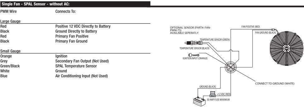
I am looking at page 5 of the document (pdf page 4), single fan SPAL sensor w/o A/C, which is what I would run (except the sensor would be my autometer wire). There are 4 grounds listed:
1. Large gauge black: battery ground. I would probably just wire this to chassis because I relocated the battery. Shouldn't matter should it?
2. Primary fan black: that's just the ground for the fan itself, I'd probably ground it with the other large gauge black wire. I presume this thing doesn't require any other relays?
3. Temp sensor black, small gauge: Is this the one that is sensitive to length? Since I will be using a 1-wire sender, I guess it doesn't matter.
4. White wire, small gauge: this is another ground presumably for the control system itself. Once again, I am unclear which wire was giving you trouble. I was going to ground this to a separate location from the the large gauge ground wires.
Any input? Also, what fan are you using this with? Is it a single fan, dual fan, single speed, dual speed? I am trying to figure my whole e-fan setup so I can just do it correctly the first time. I currently have a T04S turbo with the HKS log manifold and custom TID (just a 90 degree elbow coming off the inlet) that required me to cut the stock fan shroud in the corner. It looks awful, and I've been meaning to get rid of it when I can work out a truly solid e-fan setup that will cool reliably and not have clearance issues.
http://www.spalusa.com/fans/automate...ts/FAN-PWM.pdf
I am looking at page 5 of the document (pdf page 4), single fan SPAL sensor w/o A/C, which is what I would run (except the sensor would be my autometer wire). There are 4 grounds listed:
1. Large gauge black: battery ground. I would probably just wire this to chassis because I relocated the battery. Shouldn't matter should it?
2. Primary fan black: that's just the ground for the fan itself, I'd probably ground it with the other large gauge black wire. I presume this thing doesn't require any other relays?
3. Temp sensor black, small gauge: Is this the one that is sensitive to length? Since I will be using a 1-wire sender, I guess it doesn't matter.
4. White wire, small gauge: this is another ground presumably for the control system itself. Once again, I am unclear which wire was giving you trouble. I was going to ground this to a separate location from the the large gauge ground wires.
Any input? Also, what fan are you using this with? Is it a single fan, dual fan, single speed, dual speed? I am trying to figure my whole e-fan setup so I can just do it correctly the first time. I currently have a T04S turbo with the HKS log manifold and custom TID (just a 90 degree elbow coming off the inlet) that required me to cut the stock fan shroud in the corner. It looks awful, and I've been meaning to get rid of it when I can work out a truly solid e-fan setup that will cool reliably and not have clearance issues.
Last edited by arghx; May 12, 2008 at 01:43 PM. Reason: added pic and questions