
She Followed Me Home, Honest

Batteries, we hate 'em.
Mine is 7 years old and needs replacement, too.
I finally got off my ***, revisited my trove of pics and used the fsm to figure out what the second hose feeding metered air is doing.
The primary duty is supplying air to the AWS solenoid, which I've deleted.
BUT, it also supplies air to the four OMP injection nozzles...and I still need those.
Fortunately, the new supply for those nozzles need not be as large as before, so the new setup I create will account for that.
Looks like I'll be pulling my intake sooner than expected.
I'm getting worried, things are going entirely too well.
Sprocket cranked right up and settled into a 1300 rpm cold idle this morning. Temps were in the 40's.
Ran perfectly and when fully warmed up...ran perfectly.
This can't be right.
I was travelling to my go-to plastic supplier to find some material for the new spacer I want to make. Before I left, I decided a 6" x 6" x 1" chunk of something like Delrin would be a good starting point. Walked in their door, went to the "cut off/scrap" bins and immediately found 30-40 blocks of black Delrin, the exact size I wanted. Because they are considered scrap, these chunks are simply sold by the pound...mine weighed 2 lbs and cost 5$.
It was too easy/serendipitous...this can't be right.


Joined: Mar 2001
Posts: 31,859
Likes: 3,243
From: https://www2.mazda.com/en/100th/
I'm getting worried, things are going entirely too well.
Sprocket cranked right up and settled into a 1300 rpm cold idle this morning. Temps were in the 40's.
Ran perfectly and when fully warmed up...ran perfectly.
This can't be right.
I was travelling to my go-to plastic supplier to find some material for the new spacer I want to make. Before I left, I decided a 6" x 6" x 1" chunk of something like Delrin would be a good starting point. Walked in their door, went to the "cut off/scrap" bins and immediately found 30-40 blocks of black Delrin, the exact size I wanted. Because they are considered scrap, these chunks are simply sold by the pound...mine weighed 2 lbs and cost 5$.
It was too easy/serendipitous...this can't be right.
Sprocket cranked right up and settled into a 1300 rpm cold idle this morning. Temps were in the 40's.
Ran perfectly and when fully warmed up...ran perfectly.
This can't be right.
I was travelling to my go-to plastic supplier to find some material for the new spacer I want to make. Before I left, I decided a 6" x 6" x 1" chunk of something like Delrin would be a good starting point. Walked in their door, went to the "cut off/scrap" bins and immediately found 30-40 blocks of black Delrin, the exact size I wanted. Because they are considered scrap, these chunks are simply sold by the pound...mine weighed 2 lbs and cost 5$.
It was too easy/serendipitous...this can't be right.
i even drove my new to me, 1980 MGB the ~200mile round trip, and not only did it run perfectly the whole time, i also got 30mpg!
Spacers?
We don't need no stinkin spacers!
As per usual, the project morphed overnight, one must never underestimate the power of the subconscious. The proposed spacer was only a way to get a secure pair of hose bungs (BAC & OMP bleeds) spliced into the space between the AFM and the throttle body. The modified plastic elbow is too awkwardly shaped and lacks sufficient wall thickness where I need it.
Last night I decided to fully commit to the project and cut up my only remaining stock elbow and modify it like the first one. I think I can do a better fitting job and no longer want the bung holes already drilled in the first version.
Cutting the elbow also made it easier to trace out the flange onto the spacer blank.
Before turning in I was just staring at the bits, planning a line of attack.
Making the rough outline of the spacer is relatively simple but making a nice looking, finished piece is tough given my lack of tools.
Sometimes it's a burden knowing how to use machine tools but lacking access to them, my handwork always suffers in comparison to machine work.
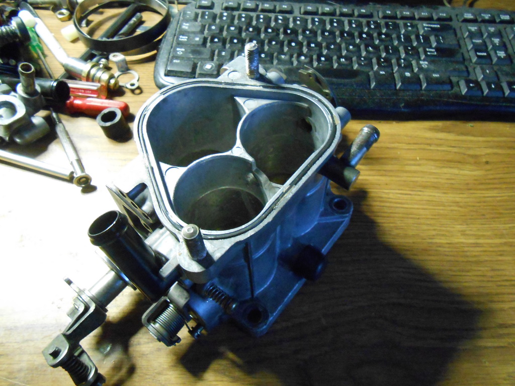
I woke up realizing that I already had a spacer...the entire back half of the throttle body.
With the secondary plates/shaft removed, most of the casting now serves only to mount the TPS and thermowax. There are some nice thick aluminum walls I can drill into, in fact I can use the outer throttle shaft hole (facing radiator) as is, no drilling required.
The size of the BAC feed is fixed by the size of the bung on the valve, so I'll just use the stock elbow from the original intake tube.
The second feed was originally sized to provide for the OMP injectors and the AWS, but with the AWS gone, I'm thinking this can be reduced in size to maybe 3/8" (from 5/8")...just guessing/hoping here. The original distribution spider for this hose (which I can only see in pictures as it's currently hidden under the exten mani) will be replaced by one of my own creation (I do still have a lathe, which is useful) and that can be made for any hose I want.
I need to go study the throttle body in situ, make sure there are no obstructions/complications I'm not seeing here at the desk and then strip my #3 backup body for machining.
I've resisted this so far but with two other complete bodies for reference, it'll be OK.
The problem is what to do about all the crappy looking linkage pieces and springs.
Ideally they'd be tumbled and chromated but naturally, I can do neither, so I guess they get cleaned and then decide.
The body should be black, I think.
I can leave the running setup intact for most of this process, so that's good.
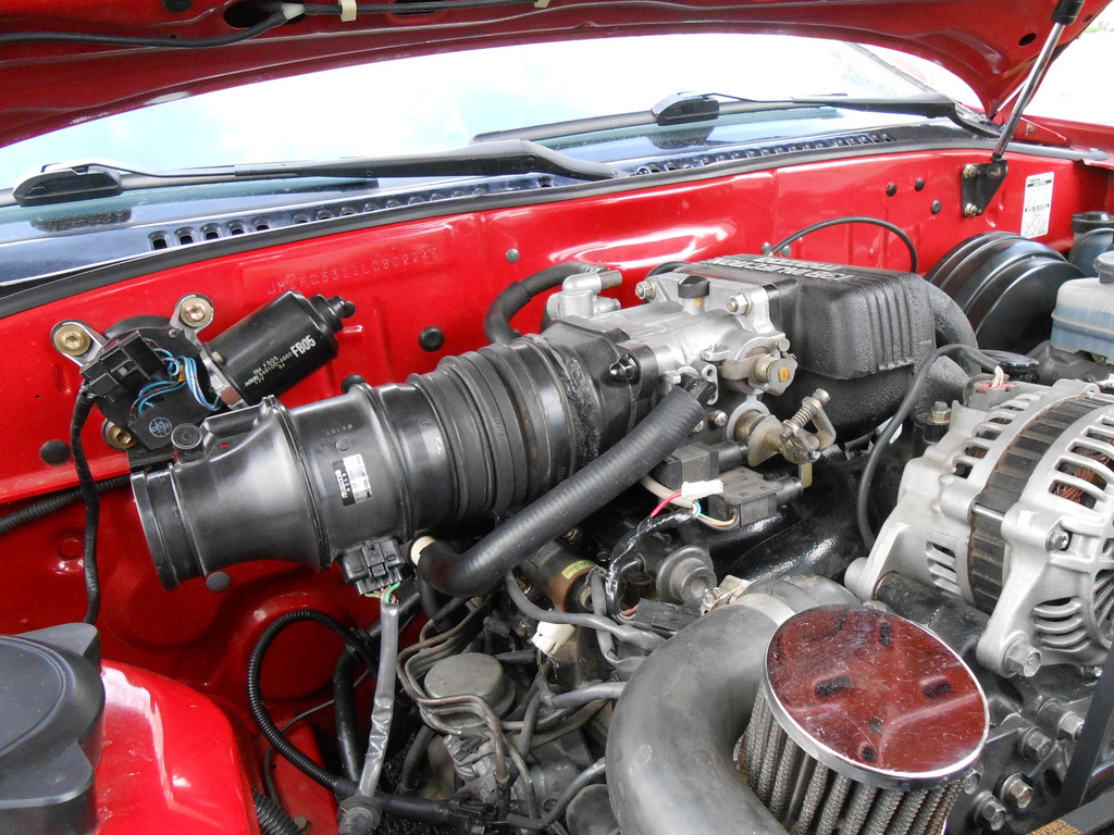
Meanwhile, there's another issue the eagle eyed may have already noticed.
The windshield washer reservoir- keystone of the original bay design- had to be deleted to make room for the air filter.
I have yet to see if it can be nicely repositioned or whether I'll need to find a whole new one, but it will be replaced.
Because streetcar.
We don't need no stinkin spacers!
As per usual, the project morphed overnight, one must never underestimate the power of the subconscious. The proposed spacer was only a way to get a secure pair of hose bungs (BAC & OMP bleeds) spliced into the space between the AFM and the throttle body. The modified plastic elbow is too awkwardly shaped and lacks sufficient wall thickness where I need it.
Last night I decided to fully commit to the project and cut up my only remaining stock elbow and modify it like the first one. I think I can do a better fitting job and no longer want the bung holes already drilled in the first version.
Cutting the elbow also made it easier to trace out the flange onto the spacer blank.
Before turning in I was just staring at the bits, planning a line of attack.
Making the rough outline of the spacer is relatively simple but making a nice looking, finished piece is tough given my lack of tools.
Sometimes it's a burden knowing how to use machine tools but lacking access to them, my handwork always suffers in comparison to machine work.
I woke up realizing that I already had a spacer...the entire back half of the throttle body.
With the secondary plates/shaft removed, most of the casting now serves only to mount the TPS and thermowax. There are some nice thick aluminum walls I can drill into, in fact I can use the outer throttle shaft hole (facing radiator) as is, no drilling required.
The size of the BAC feed is fixed by the size of the bung on the valve, so I'll just use the stock elbow from the original intake tube.
The second feed was originally sized to provide for the OMP injectors and the AWS, but with the AWS gone, I'm thinking this can be reduced in size to maybe 3/8" (from 5/8")...just guessing/hoping here. The original distribution spider for this hose (which I can only see in pictures as it's currently hidden under the exten mani) will be replaced by one of my own creation (I do still have a lathe, which is useful) and that can be made for any hose I want.
I need to go study the throttle body in situ, make sure there are no obstructions/complications I'm not seeing here at the desk and then strip my #3 backup body for machining.
I've resisted this so far but with two other complete bodies for reference, it'll be OK.
The problem is what to do about all the crappy looking linkage pieces and springs.
Ideally they'd be tumbled and chromated but naturally, I can do neither, so I guess they get cleaned and then decide.
The body should be black, I think.
I can leave the running setup intact for most of this process, so that's good.
Meanwhile, there's another issue the eagle eyed may have already noticed.
The windshield washer reservoir- keystone of the original bay design- had to be deleted to make room for the air filter.
I have yet to see if it can be nicely repositioned or whether I'll need to find a whole new one, but it will be replaced.
Because streetcar.
Joined: Mar 2001
Posts: 31,859
Likes: 3,243
From: https://www2.mazda.com/en/100th/
the S4 and FD both use a 6mm hose for the OMP injectors, so great idea, just put the hose where the secondary throttle plates are and call it good!

Where does your windshield washer reservoir live? If it's different in S5s than S4s, you might like the S4 location. It lives up under the fender and behind the bumper completely out of sight. You'd have to drill a hole in your ABS cover thing, but paint the lid black to match the ABS (or find one at the yard), and I think it'd look at least as good as factory.
They are the same and I still have the stocker...which I dislike for two reasons:
-Impossible to check the level easily, and
-The rubber gasket sealing the fill neck to the tank leaks.
I hope to rework the mount for the unit I just removed and find a clever spot for it, hopefully, near where it was.
Temporarily I have bigger fish to fry.
-Impossible to check the level easily, and
-The rubber gasket sealing the fill neck to the tank leaks.
I hope to rework the mount for the unit I just removed and find a clever spot for it, hopefully, near where it was.
Temporarily I have bigger fish to fry.
It's easy to check the level: when the light comes on while you're throwing it into a corner, it's time to refill! :-) I don't know anything about the rubber gasket on the fill neck though. I haven't had the thing out yet.
Joined: Mar 2001
Posts: 31,859
Likes: 3,243
From: https://www2.mazda.com/en/100th/
i found your thermowax spec, �X���b�g���̃����e�i���X
How interesting.
Wish my throttle body looked like that.
According to that chart (mm of thermowax extension>temp), mine is right on the button.
I installed the two hose bungs on the throttle body, the big one (BAC) in old shaft hole (considerably enlarged (watch out drilling that, the bronze bush is very grabby!) and the smaller one (oil injector feed) on the top (not my first choice but the best hose routing).
The body I'm working with has no thermowax linkage, that will be transferred over from the body in use now. Before I did that there were errands to run, car ran beautifully.
Right up till I pulled in the lot at home and she went crazy.
Coasted into a space, popped the hood and see the intake laying on the manifold...the glue joint on my adaptor failed, it just fell apart.
Great, I'd just cut/glued my last original part, using the exact same technique.
Today I'll go visit the plastic supplier, see what he says.
TBH, I'd always worried about the glue joint, the whole assembly hangs and there's a lot of leverage/force cantilevered off it. I had even imagined a mechanical support mechanism, but only in the context of "oh, that might be nice in the future".
The future is now, apparently.
Actually, I don't think it will be necessary, I just need a better adhesive.
And I knew things were going too well.
"When life hands you lemons, look for the silver lining".
Today's niblet of philosophy is just how it worked for me.
I didn't even use the "purdy" throttle body pictured above.
Early AM found me in the lot, pulling the throttle body, getting ready to swap over the thermowax assembly to the newly bunged ("purty") body in the pic above.
It occurred to me though that it might be easier to just add the large bung to the shaft hole and leave the thermowax in place...if I could get away with just one feed.
A quick trip to Ace Racing fixed me right up.
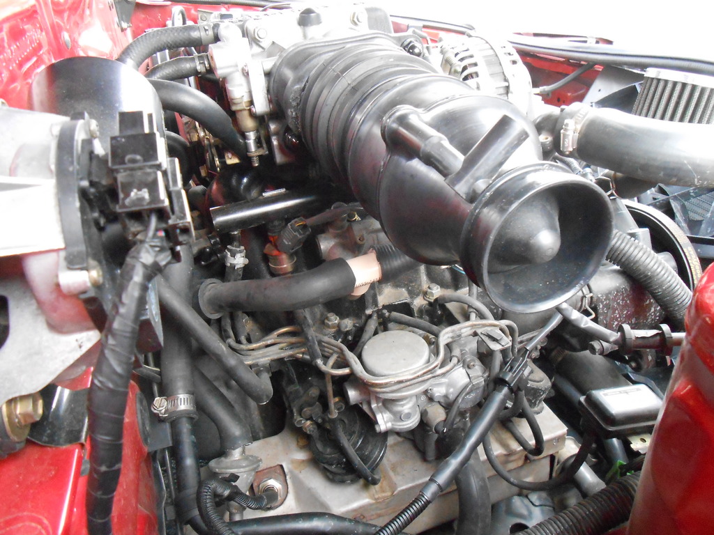
Ace provided a plumbing "tee" ($.79!) that fit the BAC port without modification or adhesive and suddenly, one port on the throttle body could feed both devices. It was easy.
And it works!
The second "improved" elbow/adaptor is in these pics, even though it's probably destined to fail at the glue joint like the first one did. I went back to the plastics place where I was told that basically, this plastic could not be reliably glued, some sort of mechanical fastening would have to happen.
I have some thoughts but will be living on the edge till I figure something out.
We have a storm moving in and I was under pressure to get Sprocket running again, so pics and descriptions are fragmented now but future shots will better show what I did.
Important thing is, she still runs.
Today's niblet of philosophy is just how it worked for me.
I didn't even use the "purdy" throttle body pictured above.
Early AM found me in the lot, pulling the throttle body, getting ready to swap over the thermowax assembly to the newly bunged ("purty") body in the pic above.
It occurred to me though that it might be easier to just add the large bung to the shaft hole and leave the thermowax in place...if I could get away with just one feed.
A quick trip to Ace Racing fixed me right up.
Ace provided a plumbing "tee" ($.79!) that fit the BAC port without modification or adhesive and suddenly, one port on the throttle body could feed both devices. It was easy.
And it works!
The second "improved" elbow/adaptor is in these pics, even though it's probably destined to fail at the glue joint like the first one did. I went back to the plastics place where I was told that basically, this plastic could not be reliably glued, some sort of mechanical fastening would have to happen.
I have some thoughts but will be living on the edge till I figure something out.
We have a storm moving in and I was under pressure to get Sprocket running again, so pics and descriptions are fragmented now but future shots will better show what I did.
Important thing is, she still runs.
Interesting thought, and I'm sure you've already gone here, but vacuum signal is uniform based on the source... How many other tees could be plumbed in to get rid of how many other annoying little vacuum lines? On my s4 there are three vacuum lines right there on the front of the manifold that all come and go to and from very similar places. Why not split the smaller two off the larger one, and minimize points of failure? There are only a very few places to pull vacuum from for different signal types/strengths, so of the 14' of vacuum line in the engine compartment, how many are actually necessary?
Truthfully, I've only briefly pondered the vac system, primarily because it's so well hidden and has always worked.
Besides, an overhaul would require I understand the whole setup and to date, that hasn't been necessary.
Replacing all the vac lines isn't really all that onerous and isn't frequently necessary, I'm not sure what serious modification would achieve to justify the effort.
You're more technically oriented than I, many/most of my projects are triggered by aesthetic concerns and so far, the vacuum system hasn't crossed the threshold.
Back to the intake...
I must confess that I've painted myself into a literal as well as figurative corner.
None of my long curated mental images of the corner airbox were detailed enough to describe exactly where the air was sourced. I had idly toyed with several ideas, all of which I now realize involve cutting metal and frankly, I'm not that committed yet.
I've been running a cone filter, completely unshrouded, for two years without noticeable problems, so the airbox can wait. Of more immediate concern is the adaptor I made and the fact it will probably fall apart soon. At the (reluctant) recommendation of the plastics guy I used a big ole soldering iron and tried to "weld" the joint. It's visible in the pics if you look.
I am not at all sold on the result but it might hold up long enough to explore options.
Especially if I rig some support for the outside end of the AFM, keep the weight from hinging on the glue joint.
She's running really well though, well enough to keep me motivated and moving forward.
The point of the vacuum system modification would be simply to reduce the number of vacuum lines and other PPFs. Those are the sorts of rubbers that like to get brittle when exposed to any amount of heat, time, or both and turn to slime if exposed to oil or other hydrocarbons. As many are no doubt intimately aware, being situated where they are pretty much guarantees vacuum gremlins. Reducing the number of vacuum lines is just a PM sort of move.
As for the intake tube adapter thing, is it the part that's bolted to the throttle body or the part that attaches to that that's giving you trouble? If the former... You might see if you can learn some sort of free CAD software and find someone with a 3D printer who doesn't mind fooling around a bit (Felix maybe?). The filament is ABS, so it shouldn't be that bad a solution. If it's the latter, you have a lathe. A short little round slug of aluminum might live in a cutoff pile somewhere and be available for cheap. That with some silicon sleeves would look pretty trick in that engine bay of yours...
As for the intake tube adapter thing, is it the part that's bolted to the throttle body or the part that attaches to that that's giving you trouble? If the former... You might see if you can learn some sort of free CAD software and find someone with a 3D printer who doesn't mind fooling around a bit (Felix maybe?). The filament is ABS, so it shouldn't be that bad a solution. If it's the latter, you have a lathe. A short little round slug of aluminum might live in a cutoff pile somewhere and be available for cheap. That with some silicon sleeves would look pretty trick in that engine bay of yours...

The next move is to revisit the process used on the first attempt (currently sitting in two pieces on the desk) and see how it can be improved.
On a completely different tack...
Having spent considerable time working with the thermowax- trying to understand the concept and linkage- I've decided the FSM's instructions for setting it up are needlessly confusing and basically, bullshit.
The "official" method involves aligning a cam and a pin at various temps and trying to achieve that result was not fruitful. I even made a spacer for the adjustment screw to try and get the action described in the manual.
I finally realized that the whole process was ignoring the end point of the linkage system- the throttle stops.
All the wax system does is crack open the throttle plates when the coolant is cold and then allow them to rest on the stops when it's hot.
In my case, I wanted a cold idle of @1200rpm and when adjusted to provide it, the cam/pin was not where the manual said it would be, the cam never dropped off the pin.
Eventually I noticed that even though the pin/cam were not "right", the plates were actually resting on the stops long before the pin/cam finished their thing.
Once the stops are hit, it doesn't matter what the cam/pin are still doing, they no longer matter.
Only after ignoring the setup from the manual and working directly with the main adjusting screw (the one that contacts the pellet) while watching the throttle stop was I able to get the result I wanted.
Fine tuning then consists of little tweaks to the screw to cover the awkward transition as the thermosensor gets close to 160�. This is where the ECU thinks it's OK to switch from the cold start map to the normal running map and for a few moments idle can get rocky if the thermowax has fully disengaged (remember that "fully disengaged" has nothing to do with the pin/cam and everything to do with the throttle stops).
Holding the adjustment for a little longer covers this little transition until the engine is really ready to support a 750 rpm idle.
My description of this is lacking but hold the throttle body in hand and pour boiling/ice water in the thermowax and it becomes pretty obvious what's going on.
It's actually a cool system, just takes a while to figure out.
Of course, a perfectly working thermowax does me no good if the AFM can fall off the throttle body, so it's back to work I go.
Joined: Mar 2001
Posts: 31,859
Likes: 3,243
From: https://www2.mazda.com/en/100th/
Joined: Mar 2001
Posts: 31,859
Likes: 3,243
From: https://www2.mazda.com/en/100th/
The point of the vacuum system modification would be simply to reduce the number of vacuum lines and other PPFs. Those are the sorts of rubbers that like to get brittle when exposed to any amount of heat, time, or both and turn to slime if exposed to oil or other hydrocarbons. As many are no doubt intimately aware, being situated where they are pretty much guarantees vacuum gremlins. Reducing the number of vacuum lines is just a PM sort of move..
the second thing is that the rack as an assembly does various jobs, and some require vacuum and some require just a fresh air feed, some even require pressure, and then there is the PCV in there too. the point being if you put a vacuum/pressure gauge on the 3 hoses on the front of the intake, you'd find that there are three different signals.
later Mazda moved to a "black box" which has a single feed for vacuum, pressure, fresh air, and pcv, and then the outputs, so the number of hoses went from like 72 to 20 or something, and then of course even later, the non return fuel system, and drive by wire gets rid of more stuff, so then you only have 6 vacuum lines
i guess the third thing is that, if i had a dollar for every thread that was something like "i just removed my vacuum rack/emissions/hose job/rats nest and now the car does/or doesn't do whatever" i'd have several hundred dollars.
you let a sleeping dog lie afterall.