
S5 TII rats nest & solenoids

Thread Starter
Full Member
Joined: Jan 2010
Posts: 90
Likes: 6
From: Greece
S5 TII rats nest & solenoids
Hi all..
I got down to replacing some of the cracked vacuum tubes in my rats nest this evening and I found out that I have 4 solenoids instead of the 3 mentioned in the FSM. The extra one is of green plug colour. My motor is an S5 Turbo2.
I searched and searched again the fora.. At first I thought that it had an S4 turbo nest fitted, but that was not the case, since I traced the green solenoid lines and they were not going to the exhaust mainfold (no flap in mine anyway). This solenoid had 3 lines connected instead of two. One was hardline T-ed to the FPR together with the Orange solenoid, one was coming under the UIM and one was running to something like a vacuum chamber. Yes, I also have that thing. It is located in the right side of the engine bay as we look at it, right behind the headlight and the coils.
I live in Europe, so that's a european model.. It originally was fitted with the N380 ECU, which I replaced. No clue if this ECU can handle this nest.
Help... I was about to believe that I comprehended the nest, but now I'm back to zero. What are all these?
I got down to replacing some of the cracked vacuum tubes in my rats nest this evening and I found out that I have 4 solenoids instead of the 3 mentioned in the FSM. The extra one is of green plug colour. My motor is an S5 Turbo2.
I searched and searched again the fora.. At first I thought that it had an S4 turbo nest fitted, but that was not the case, since I traced the green solenoid lines and they were not going to the exhaust mainfold (no flap in mine anyway). This solenoid had 3 lines connected instead of two. One was hardline T-ed to the FPR together with the Orange solenoid, one was coming under the UIM and one was running to something like a vacuum chamber. Yes, I also have that thing. It is located in the right side of the engine bay as we look at it, right behind the headlight and the coils.
I live in Europe, so that's a european model.. It originally was fitted with the N380 ECU, which I replaced.
No clue if this ECU can handle this nest.Help... I was about to believe that I comprehended the nest, but now I'm back to zero. What are all these?

Does Greece have emission testing? If not, throw the solenoids out and delete the emissions.
You'll need to snap a picture of what you have so we have an idea . That'll help.
The green is usually the turbo solenoind .
You'll need to snap a picture of what you have so we have an idea . That'll help.
The green is usually the turbo solenoind .
Thread Starter
Full Member
Joined: Jan 2010
Posts: 90
Likes: 6
From: Greece
Yep we have smog test at idle and at 3000rpm...
I will take a picture in the day cause I put it back together and didn't take any already. Dumb me... It's nothing special though, just an extra green solenoid with 3 lines attached and connected straight to the hardlines..
I will take a picture in the day cause I put it back together and didn't take any already. Dumb me... It's nothing special though, just an extra green solenoid with 3 lines attached and connected straight to the hardlines..
Thread Starter
Full Member
Joined: Jan 2010
Posts: 90
Likes: 6
From: Greece
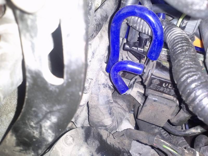
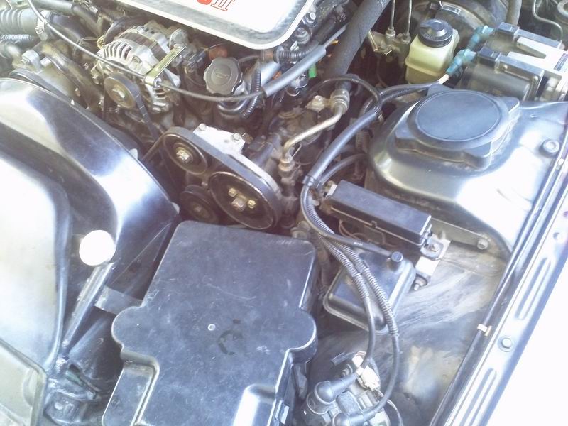
OK so this is the green solenoid..

Please ignore the adjacent one, it is just a replacement I made for my faulty ACV switching solenoid..
This is the other side of it..

It certainly is not turbo port related.
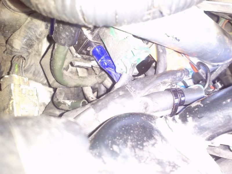
The wastegate duty cycle solenoid is removed since I have an EBC. You can see its hardlines open.
Here you can see the T and the check valve for the vaccum chamber..

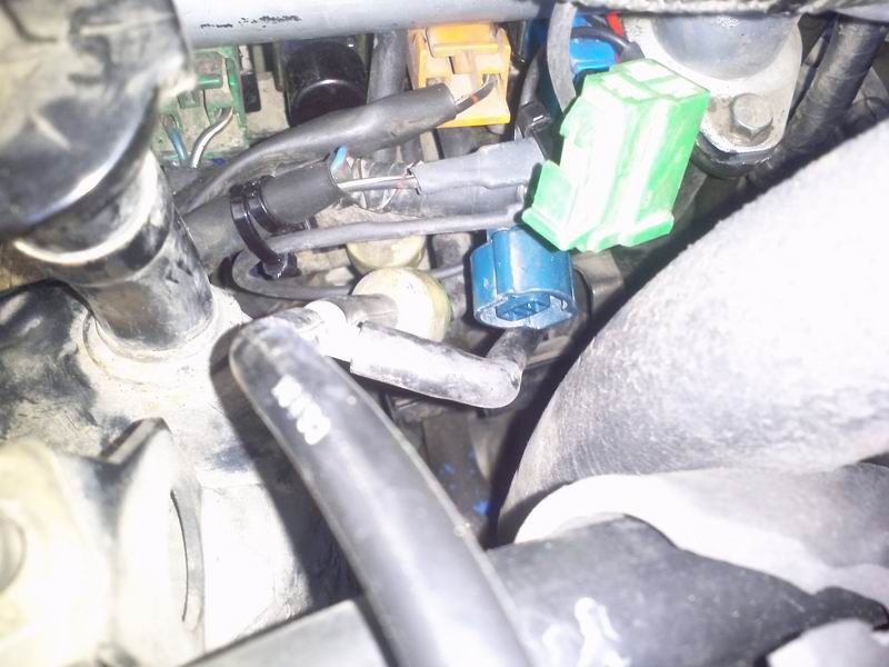
And here is the vacuum chamber itself..

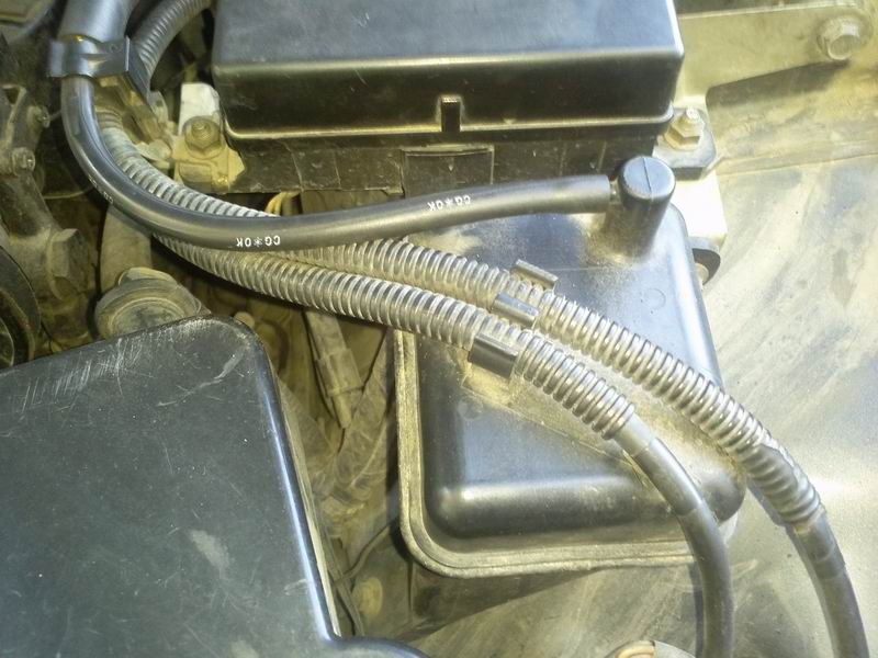
Finally an overview:

Help...
Please ignore the adjacent one, it is just a replacement I made for my faulty ACV switching solenoid..
This is the other side of it..
It certainly is not turbo port related.
The wastegate duty cycle solenoid is removed since I have an EBC. You can see its hardlines open.
Here you can see the T and the check valve for the vaccum chamber..
And here is the vacuum chamber itself..
Finally an overview:
Help...
Last edited by infernal; May 6, 2013 at 04:31 AM.

Trending Topics
Thread Starter
Full Member
Joined: Jan 2010
Posts: 90
Likes: 6
From: Greece
Sorry for the repost, I am not permitted to edit my former posts..
OK so this is the green solenoid..
Please ignore the adjacent one, it is just a replacement I made for my faulty ACV switching solenoid..
This is the other side of it..
It certainly is not turbo port related.
The wastegate duty cycle solenoid is removed since I have an EBC. You can see its hardlines open.
Here you can see the T and the check valve for the vaccum chamber..
And here is the vacuum chamber itself..
Finally an overview:
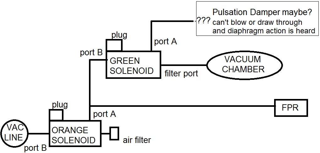
I also made a drawing of what I think I found out so far, so that I can help you help me. I may be wrong though..
Here it is:
Thanks for your time!
OK so this is the green solenoid..
Please ignore the adjacent one, it is just a replacement I made for my faulty ACV switching solenoid..
This is the other side of it..
It certainly is not turbo port related.
The wastegate duty cycle solenoid is removed since I have an EBC. You can see its hardlines open.
Here you can see the T and the check valve for the vaccum chamber..
And here is the vacuum chamber itself..
Finally an overview:
I also made a drawing of what I think I found out so far, so that I can help you help me.
I may be wrong though..Here it is:
Thanks for your time!


Joined: Mar 2001
Posts: 31,857
Likes: 3,243
From: https://www2.mazda.com/en/100th/
hmm interesting i see that green solenoid and vacuum tank are actually supposed to be on the EU S5, although the diagram isn't good enough to see what they are for.
the US and JDM cars don't have it, so i dunno what it does.
the US and JDM cars don't have it, so i dunno what it does.
Thread Starter
Full Member
Joined: Jan 2010
Posts: 90
Likes: 6
From: Greece
Oooops given that I have a JDM ECU installed, I might well not use any of those anymore..
Yes, I didn't find the courage to remove the UIM, but I plan to do so soon. Then we will know for sure what it does, if no input is made until then..
Yes, I didn't find the courage to remove the UIM, but I plan to do so soon. Then we will know for sure what it does, if no input is made until then..
Since you're using a non EU ECU, I'd set it up as an S5 TII. If it's a long block,
just use the solenoids it came with and disregard that vacuum tank.
If you're using an EBC, you will disable the solenoid valve.
Follow this :
Thread Starter
Full Member
Joined: Jan 2010
Posts: 90
Likes: 6
From: Greece
***UPDATE! If I saw correctly, my stock FPR has 2 vacuum lines, one before and one after the diaphragm, so maybe the green solenoid and the vacuum tank are connected to the extra port on the side of the injectors on the FPR?
So based on this, I made a new drawing..
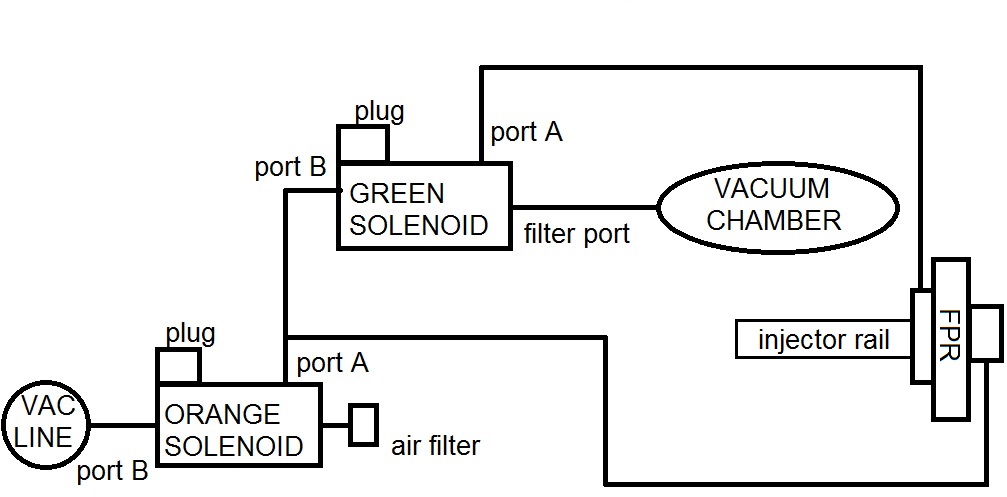
Could it be something like this?
Thanks again..
So based on this, I made a new drawing..
Could it be something like this?
Thanks again..
Last edited by infernal; May 8, 2013 at 02:56 PM. Reason: Added drawing...
I did some looking around and I think the top drawing you have is correct.
The vacuum line nearest fuel rail needs vacuum source only to assist in hot starts to alter fuel pressure.
The right side needs both vaccum / boost so as it is hooked up to orange is correct.
OR...you can eliminate the solenoids and use the manifold as vacuum or boost source for the FPR. It shouldn't affect emissions. Just another 25+ yr old part don't need to worry about.
Thread Starter
Full Member
Joined: Jan 2010
Posts: 90
Likes: 6
From: Greece
I'm back and hopefully got my hands on a removed hardline assembly for a few mins, so I figured out the pipework lol.
It goes like this:
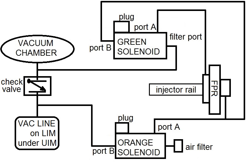
This is the final, correct layout.
So the green solenoid is for FPR control together with the orange one.. But what does it do?
First of all, does anyone know how a Fuel Pressure Regulator with 2 vac lines work? Should the two lines work as if the diaphragm is placed between them, I may have a clue..
VANHALEN, as far as I can see the green solenoid somehow ensures the inner vac fitting of the FPR always sees vacuum, even on boost. I don't know the use it makes of it, neither how a 2 line FPR works..
If anyone knows how a Fuel Pressure Regulator *with 2 vac fittings* works, please shed some light.
Thanks!
It goes like this:
This is the final, correct layout.
So the green solenoid is for FPR control together with the orange one.. But what does it do?
First of all, does anyone know how a Fuel Pressure Regulator with 2 vac lines work? Should the two lines work as if the diaphragm is placed between them, I may have a clue..
VANHALEN, as far as I can see the green solenoid somehow ensures the inner vac fitting of the FPR always sees vacuum, even on boost. I don't know the use it makes of it, neither how a 2 line FPR works..
If anyone knows how a Fuel Pressure Regulator *with 2 vac fittings* works, please shed some light.
Thanks!

Joined: Mar 2001
Posts: 31,857
Likes: 3,243
From: https://www2.mazda.com/en/100th/
if its pressure it lets them lower fuel pressure interdependently of the manifold pressure.
why they want to do this, and why only in europe is an unknown.
Thread Starter
Full Member
Joined: Jan 2010
Posts: 90
Likes: 6
From: Greece
Thanks for the input j9fd3s!
As I understand it:
The rail (EU extra) side gets [vacuum only] or [vacuum/pressure] determined by the green solenoid.
The other (normal) side is [vacuum/pressure] or [atmospheric] determined by the orange solenoid, as in all FCs.
When and under what conditions are those solenoids activated still remains a mystery, as I don't have a EUspec FSM and my original ECU is gone so I can't test their operation myself..

Thread
Thread Starter
Forum
Replies
Last Post
MidnightOwl
2nd Generation Specific (1986-1992)
1
Sep 25, 2015 10:24 PM