When you click on links to various merchants on this site and make a purchase, this can result in this site earning a commission. Affiliate programs and affiliations include, but are not limited to, the eBay Partner Network.
Hey guys, I'm in the process of prepping to re assemble the TB to the manifold, I took it out to degrease/clean the TB, and shoot some degreaser/compressed air into the thermowax in an attempt to free it up.
Long story short, I'm trying to read the vacc diagram online, and it seems to do a very good job from the intake manifold forward. Not so much for the throttle body lines. I've got the lines color coded in each picture below to where I believe they go, but if you guys could chime in and make sure i'm in the right direction, i'd appreciate it. (For the record, the colors I'm using have no relation whatsoever to the colors used on the hose routing diagram, I just picked those because they are easy to see in the photos)
Also worth mentioning is the car was originally an Auto, I did the transmission swap myself. It has the original Auto motor, tb, etc.
There is a third bung you cannot see (colored in green) as it is hidden by the bracket. Second bung (blue) goes to a bung under the TB itself, Yes I know the check valve broke. Damn old solid vac lines.
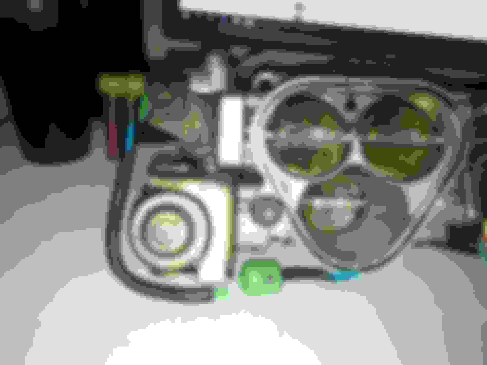
The other end of the blue line, you can see the Vacc line going to the bung under the TB in this picture. Take note of the far right, the orange and black question marks. I have no idea where those pair up.
Red to red, first vacc nipple on the TB i have going to this.
Lower left is the other part of the red vacuum line, as it is red. I have no idea where the end of that hose goes to, or where the vac line just laying on the manifold goes either. My money says they have to go to either the orange or black question mark bungs on the TB in the earlier photo. If someone could help clarify for me i'd greatly appreciate it.
Also, I noticed this while going through the whole manifold removal. Anyone have any idea where this guy is supposed to run to?
The bung in question here is the one with the black question marks, an arrow is pointing to it. <br/><br/>For reference, the BAC is top middle, and the purple line is the hose going to the BAC from the Intake pipe.
After tons of digging, I've come up with the homes for the regular vacc hoses, however I am still stumped at that Bung in the last photo.
Anyone mind pointing me in the right direction? I'v
e scoured the FSM and can't seem to find it in any diagrams, I'm sure I have to be overlooking it.
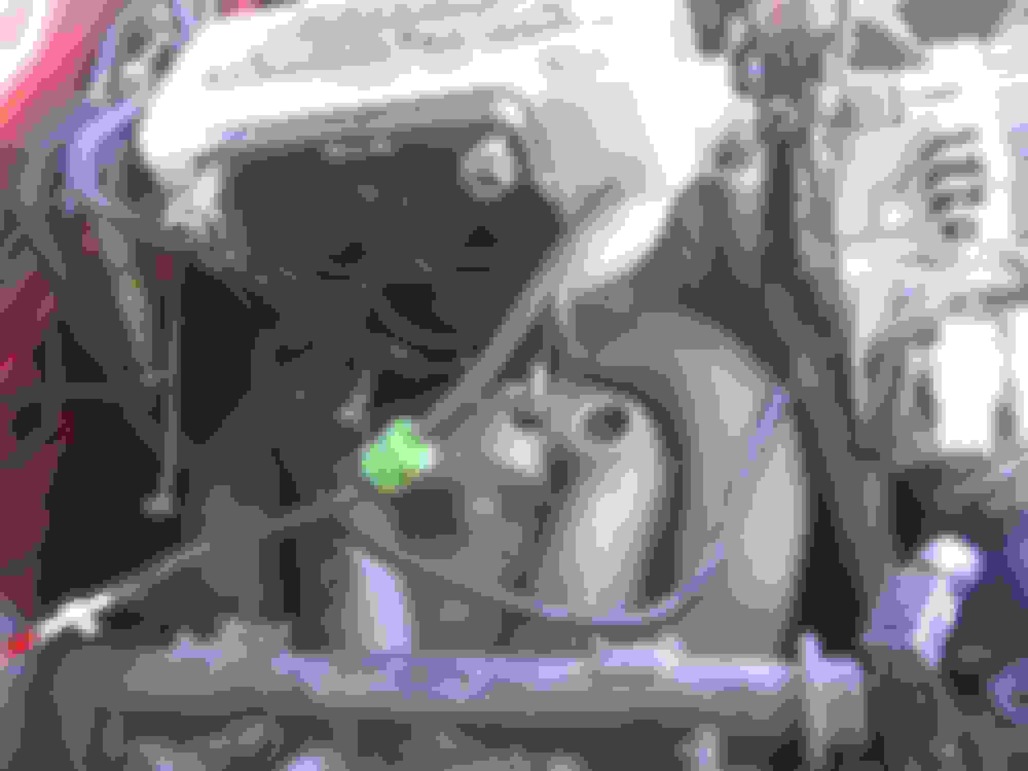
Better picture. You can see in this one the BAC valve, with the hose leading to the intake removed for greater clarity. The bung in question is circled in yellow. Anyone have any idea as to where it is supposed to route to?
After tons of digging, I've come up with the homes for the regular vacc hoses, however I am still stumped at that Bung in the last photo.
Anyone mind pointing me in the right direction? I'v
e scoured the FSM and can't seem to find it in any diagrams, I'm sure I have to be overlooking it.
Better picture. You can see in this one the BAC valve, with the hose leading to the intake removed for greater clarity. The bung in question is circled in yellow. Anyone have any idea as to where it is supposed to route to?
This pipe would go the the cold start assist pump located up by the charcoal canister. If your car doesn't have the small jug of green liquid next to the charcoal canister, then it was either removed or never installed at the factory. All S5 cars had this piece installed on the intake. It's just a check valve and can be safely removed and blocked off with a plate. Or you can leave it on... it doesn't do anything.