
S5 n/a Vacuume Hosing...


Thread Starter
Nekurd
Joined: Feb 2006
Posts: 1,129
Likes: 0
From: California
S5 n/a Vacuume Hosing...
Uhh... I got most of the from looking at the service manual but there are a few that werent covered or too hard to tell. So I was wondering if you forum-heads would help.
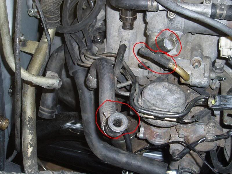
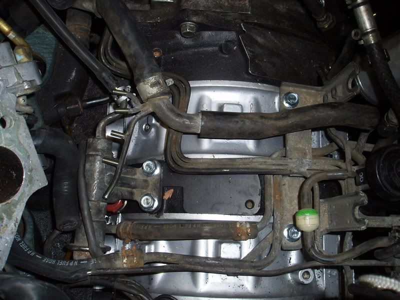
Where do these go?
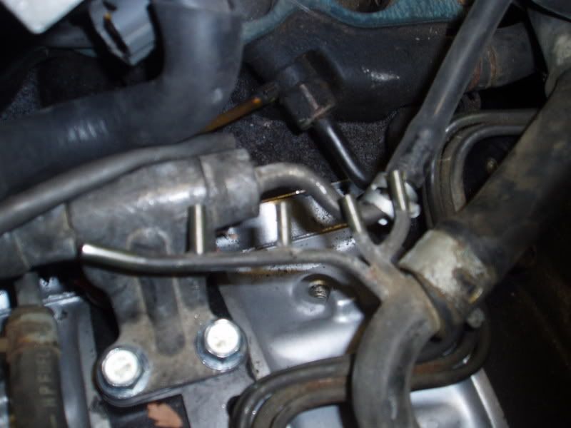
This?
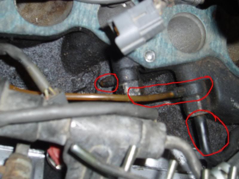
These too...
Cant forget these...
And lastly this...
Please help, I would like to finish the hosing so I can move on the the electrical part of the swap. Thanks
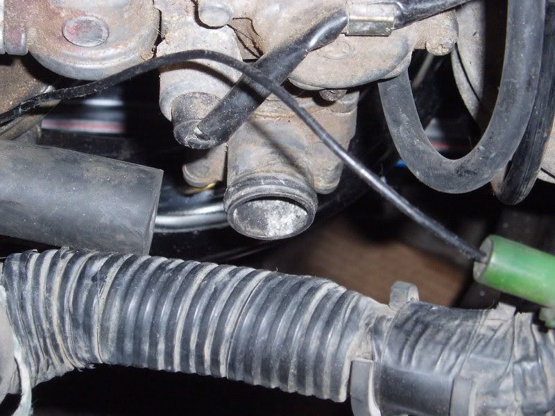
Where do these go?
This?
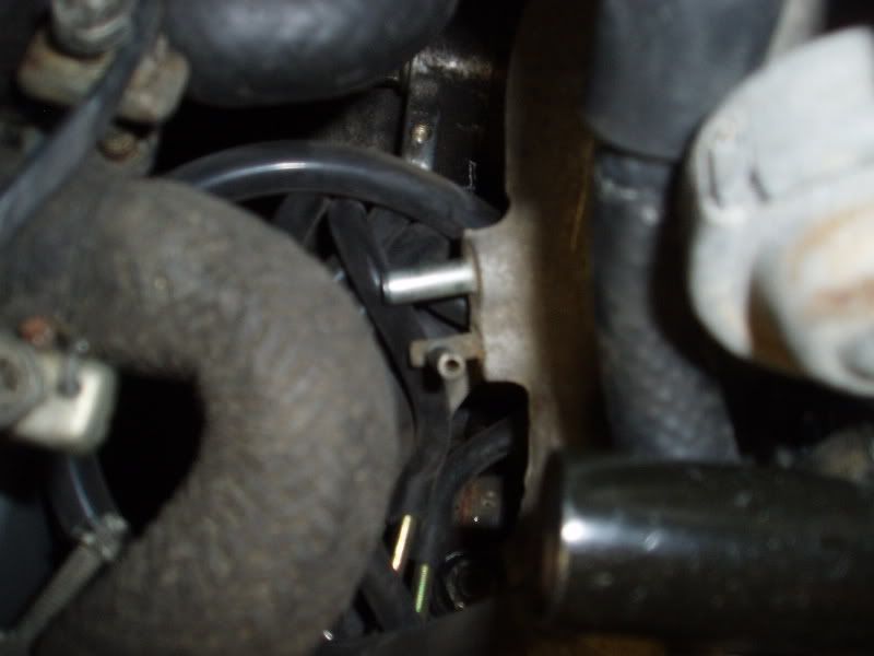
These too...
Cant forget these...
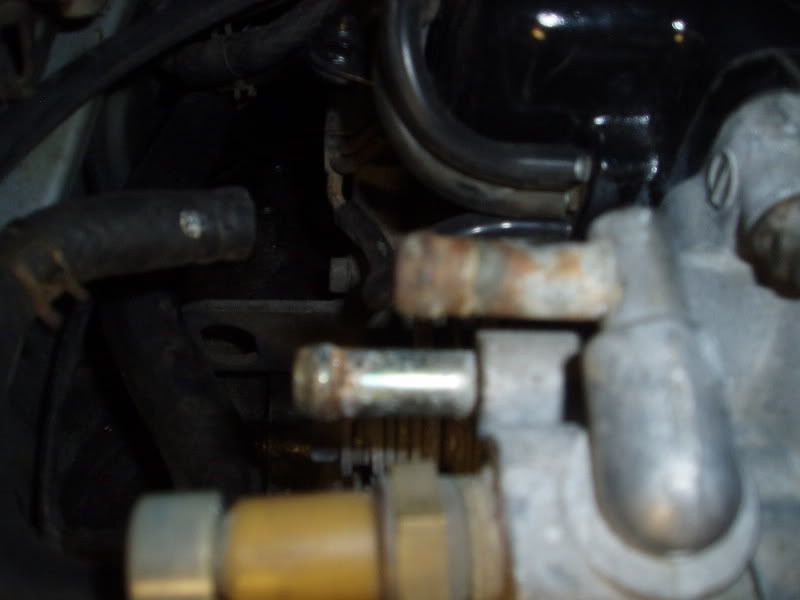
And lastly this...
Please help, I would like to finish the hosing so I can move on the the electrical part of the swap. Thanks
Lives on the Forum


Joined: Oct 2004
Posts: 5,182
Likes: 172
From: Japanabama
Top pic (top to bottom): 1. To the big intake hose (it has two outlets for big vacuum hoses, that's for one of them)
2. No where, it doesn't matter
3. To the brake booster... it goes into the bronze hose to the left of it
Second pic: That's where the air relief silencer hose hooks up... it's basically there to keep the air control valve from making annoying noises. Originally it hooks up to a silencer caninster under the front bumper, but most cars probably don't have these any more... The hose to the left of that looks like the split air pipe (part of it). Althought if it connectors to the lower intake manifold it's one of the vacuum hoses that goes to the intake hose.
(actually, that IS the other hose that connectors to the intake hose)
Third pic: IIRC these should be capped off.
Fourth pic: Those aren't vacuum hoses, theyh're coolant hoses. One comes from the BAC and one comes from the rear of the block (there should be a thing sticking up frm the rear iron). The bottom one goes to the block and top one connectors with an L-shaped hose to the BAC.
Fifth pic: One of those goes into the little actuator on the throttle body, the other one goes almost straight down but I don't remember where (down the FSM...).
Last edited by Valkyrie; Oct 27, 2006 at 07:20 PM.

I think Valkyrie has got it.
just some comments:
first pic: the second (top to bottom) circled item goes to the stock warm up coolant reservoir (used to actually inject coolant into the manifold on really cold days). i'm guessing you aren't using that. cap that off, and also cap the vac nipple on that little valve on the manifold.
third pic: cap them off if you aren't using them, but if you have swapped over all the S5 vacuum stuff and S5 ECU then you will need to use them. those are simply a source of vacuum (anything vac nipples AFTER the throttle body is just a vacuum source).
fifth pic: one goes to the no.2 secondary throttle plate actuator, and i think the other connector just needs to go to a source of vacuum (i.e. somewhere on the manifold)\
i've attached a diagram that might help. note though that this diagram is for an actual S5 car.
Last edited by coldfire; Oct 28, 2006 at 03:25 AM.
Thread Starter
Nekurd
Joined: Feb 2006
Posts: 1,129
Likes: 0
From: California
Sorry to bring this back, since its been awhile and you guys probably thought I'd be done with it, but I'm not. Been doing everything except for this.
1st Picture: (From top to bottom) Is the big outlet suppose to connect to the tubing for the intake? The one below that, bronze, that still isn't connected to anything but I'm going to cap it since coldfire said it should. And for the second cap, are you talking about the little outlet to the right? Last one I already connected it to the piping to the left.
2nd Picture: It actually looks like it would connect to the hose on my RB center section exhaust system. Yes? No?
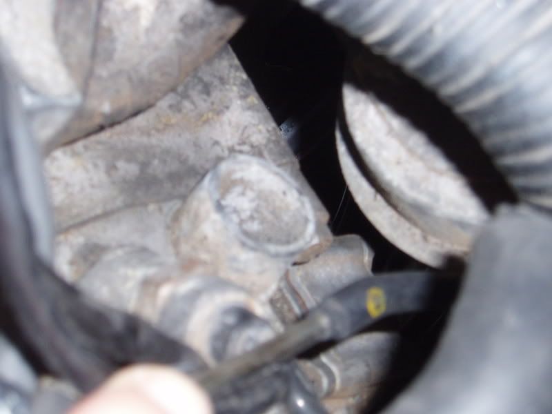
3rd Picture: I think I have something connected to those, I'll check again to see if I did. If not, I'll cap them.
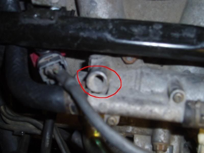
5th Picture: The one on the right is said to go to "H" (shown in diagram). Is that the outlet that is already capped shown in the 1st picture?
The one on the left goes to this?
This outlet is on the LIM and is closest to the front of the engine. It looks like it might hook up to the air pump, can't tell right now since mine is being shipped to me as we speak. Does that sound right?
Should I not worry about this? It looks like it should be connected to something.
There is also another rack for vacuum hoses ontop of the engine and under the LIM. Couldn't get a picture since I lost my 12mm socket . It weird that I have it since all the diagrams don't show it. Could they be fuel lines? I'll try and get pictures of it later.
1st Picture: (From top to bottom) Is the big outlet suppose to connect to the tubing for the intake? The one below that, bronze, that still isn't connected to anything but I'm going to cap it since coldfire said it should. And for the second cap, are you talking about the little outlet to the right? Last one I already connected it to the piping to the left.
2nd Picture: It actually looks like it would connect to the hose on my RB center section exhaust system. Yes? No?
3rd Picture: I think I have something connected to those, I'll check again to see if I did. If not, I'll cap them.
5th Picture: The one on the right is said to go to "H" (shown in diagram). Is that the outlet that is already capped shown in the 1st picture?
The one on the left goes to this?
This outlet is on the LIM and is closest to the front of the engine. It looks like it might hook up to the air pump, can't tell right now since mine is being shipped to me as we speak. Does that sound right?
Should I not worry about this? It looks like it should be connected to something.
There is also another rack for vacuum hoses ontop of the engine and under the LIM. Couldn't get a picture since I lost my 12mm socket
. It weird that I have it since all the diagrams don't show it. Could they be fuel lines? I'll try and get pictures of it later.
you are asking questions twice (already answered in this thread), but for further clarification:
yes, yes, and if you aren't using that outlet/nipple cap it also.
No. That is the outlet for the ACV. Stock, it is connected to a "silencer". if your ACV is still operational, air pump air will come out that outlet under certain conditions. technically you can just leave it uncapped but it will make some noise. and don't cap it.
again, these are just nipples into the intake manifold for vacuum source. you may not need to use them, so yeah cap them.
one of those (the one that goes down to "H") just has to hook up to a vacuum source (any nipple on the manifold). yes, the other one goes to the actuator in your picture. look at the S4 vac diagram to make sure you have the correct routing.
i can't really see what you are refering to. but i believe that is the air source for the 6pi actuators. in my diagram i showed you, that goes to "C". but i can't really tell from that pic.
that is not a connection to anything.
i'm pretty sure you are just referring to the vacuum hard lines under the manifold, that sit on top of the block. these are just connections for the vac lines. if you look at the diagram i posted, that thing is basically the connection between the solenoids and everything on the side of the manifold.
Originally Posted by Druken
1st Picture: (From top to bottom) Is the big outlet suppose to connect to the tubing for the intake? The one below that, bronze, that still isn't connected to anything but I'm going to cap it since coldfire said it should. And for the second cap, are you talking about the little outlet to the right?
2nd Picture: It actually looks like it would connect to the hose on my RB center section exhaust system. Yes? No?
3rd Picture: I think I have something connected to those, I'll check again to see if I did. If not, I'll cap them.
5th Picture: The one on the right is said to go to "H" (shown in diagram). Is that the outlet that is already capped shown in the 1st picture?
The one on the left goes to this?
The one on the left goes to this?
This outlet is on the LIM and is closest to the front of the engine. It looks like it might hook up to the air pump, can't tell right now since mine is being shipped to me as we speak. Does that sound right?
Should I not worry about this? It looks like it should be connected to something.
There is also another rack for vacuum hoses ontop of the engine and under the LIM. Couldn't get a picture since I lost my 12mm socket . It weird that I have it since all the diagrams don't show it. Could they be fuel lines? I'll try and get pictures of it later.
. It weird that I have it since all the diagrams don't show it. Could they be fuel lines? I'll try and get pictures of it later.
Thread Starter
Nekurd
Joined: Feb 2006
Posts: 1,129
Likes: 0
From: California
Okay, Thanks for clarifying it for me even further. Heh...
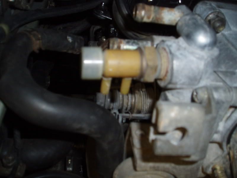
So this is what I was talking about the other hard lines. I made a mistake in recalling them for fuel lines.. pish.. but where would these go?
Next, after looking for the lines above, I noticed that this orange line was cut and seems like there was another one but was cut right at the nipple. There are also a vacuume line for each.
Thanks again for the help.
Trending Topics


ole blue
Joined: Nov 2005
Posts: 129
Likes: 1
From: Wilmington, NC
Damn... has this engine ran with that oil injector(s) not working?
From post #7, Four of those five lines goes to each oil injector. I am unsure of where the fifth one goes at the moment....The oil injectors only get routed to "Metered" air, not vacuum (incase you end up taking emissions off)
In your third pic, those orange oil injection lines should get hooked up to the Oil Metering Pump. On the passengers side of the front cover; in front of the exhaust...I am not sure if it matters what hole you attach them to at the OMP, but i wanna say they each have a specific hole to be attached to. There is a great write-up on replacing your oil injectors for very cheap.
Originally Posted by Druken
Okay, Thanks for clarifying it for me even further. Heh...
So this is what I was talking about the other hard lines. I made a mistake in recalling them for fuel lines.. pish.. but where would these go?
So this is what I was talking about the other hard lines. I made a mistake in recalling them for fuel lines.. pish.. but where would these go?
one end of that large vac hard line connects to the Accelerated Warmup Solenoid, and the other end connects to the intake funnel (BEFORE the throttle body, and the BACV also connects to that end).
Next, after looking for the lines above, I noticed that this orange line was cut and seems like there was another one but was cut right at the nipple. There are also a vacuume line for each.
1) switch to premixing 2-stroke oil into your gas.
OR
2) replace those OMP oil lines and ensure that your injectors and OMP are in good working order
Thread Starter
Nekurd
Joined: Feb 2006
Posts: 1,129
Likes: 0
From: California
Thanks guys, I think I got everything down except for these last two, I SWEAR!... I think... 
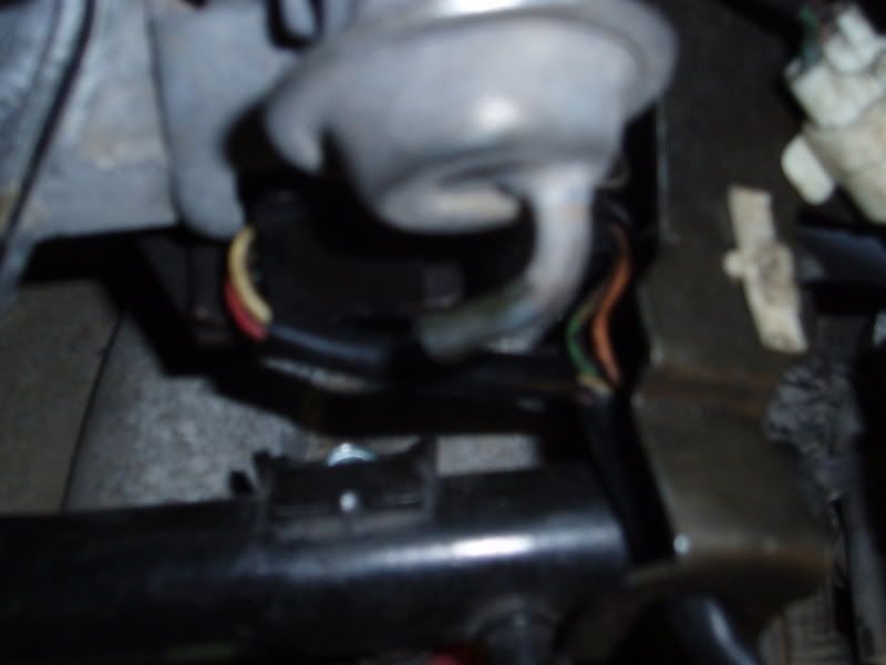
In the picture, I know the hose circled in red goes behind the dynamic chamber... but where does the one circled in teal go to?
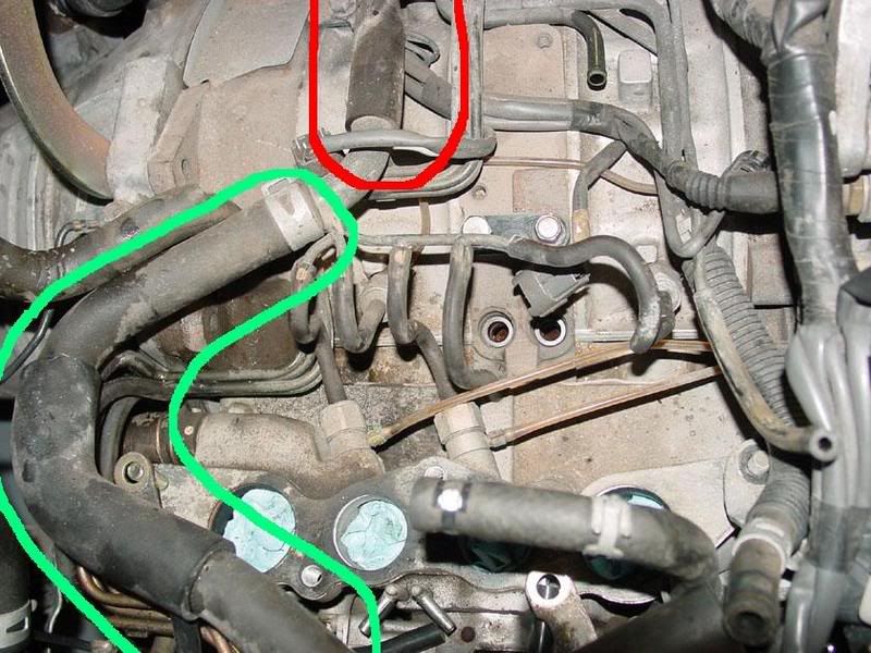
In the picture, I know the hose circled in red goes behind the dynamic chamber... but where does the one circled in teal go to?
actually i think the side circled in red goes to the Accelerated Warmup Solenoid and THEN to the dynamic chamber.
the other side, "teal", simply goes to the intake funnel (before the throttle body).
the other side, "teal", simply goes to the intake funnel (before the throttle body).
Winter sucks
Joined: Jan 2004
Posts: 3,083
Likes: 0
From: Newberg, Oregon
I have a play by play archive of picture that I took as I took pieces off of my S5 NA.. I was stripping the engine, but I took pictures at each step. Well, pretty much anyways.
You interested? I might be able to post them.
You interested? I might be able to post them.
Originally Posted by micaheli
I have a play by play archive of picture that I took as I took pieces off of my S5 NA.. I was stripping the engine, but I took pictures at each step. Well, pretty much anyways.
You interested? I might be able to post them.
You interested? I might be able to post them.
Winter sucks
Joined: Jan 2004
Posts: 3,083
Likes: 0
From: Newberg, Oregon
I'll post them later today if thats cool. I *CAN* post them. Its just a PITA.  so I was making sure there was interest before I went off and spent the time to do it.
If I had more time, I'd actually put labels in the pictures and point out what everything is. Would probably be great for the archives.
so I was making sure there was interest before I went off and spent the time to do it. If I had more time, I'd actually put labels in the pictures and point out what everything is. Would probably be great for the archives.
Winter sucks
Joined: Jan 2004
Posts: 3,083
Likes: 0
From: Newberg, Oregon
Originally Posted by micaheli
I have a play by play archive of picture that I took as I took pieces off of my S5 NA.. I was stripping the engine, but I took pictures at each step. Well, pretty much anyways.
You interested? I might be able to post them.
You interested? I might be able to post them.
For people reading this in the future when the link below doesn't work. PM me and I'll post'em up again.
http://picasaweb.google.com/micaheli/RX7EnginePics
Enjoy.
--Micah

Thread
Thread Starter
Forum
Replies
Last Post
ls1swap
3rd Generation Specific (1993-2002)
17
Jun 3, 2024 03:25 PM