
S5 JDM turbo vacuum routing

Thread Starter
Joined: Nov 2006
Posts: 2,406
Likes: 2
From: Indiana
S5 JDM turbo vacuum routing
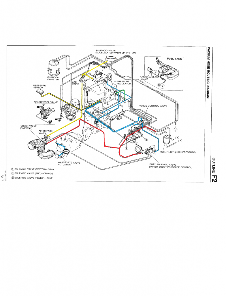
I went through my vacuum routing today and want to makes sure I have this correctly.
One thing not on there is that I have the rear top port capped. Is that both a boost and vacuum source? I'd like to use that for my boost gauge sender.
Also I'd like to keep the OEM routing for the PCV and charcoal canister. I didn't complete the red lines to the canister...but you get the idea.
One thing not on there is that I have the rear top port capped. Is that both a boost and vacuum source? I'd like to use that for my boost gauge sender.
Also I'd like to keep the OEM routing for the PCV and charcoal canister. I didn't complete the red lines to the canister...but you get the idea.

We are in the People's Ecotopian Republic of Austin so have to keep the emissions in place and get probed annually. The probes have been satisfying for the govt to date.
The top hose on the back on ours curls under the UIM and connects to something but I can't see what. Unfortunately, we had the UIM off a few weeks ago to replace a split fuel line and could have taken pictures to trace the lines. I do have this one I took to show the boy where the gas leak was...
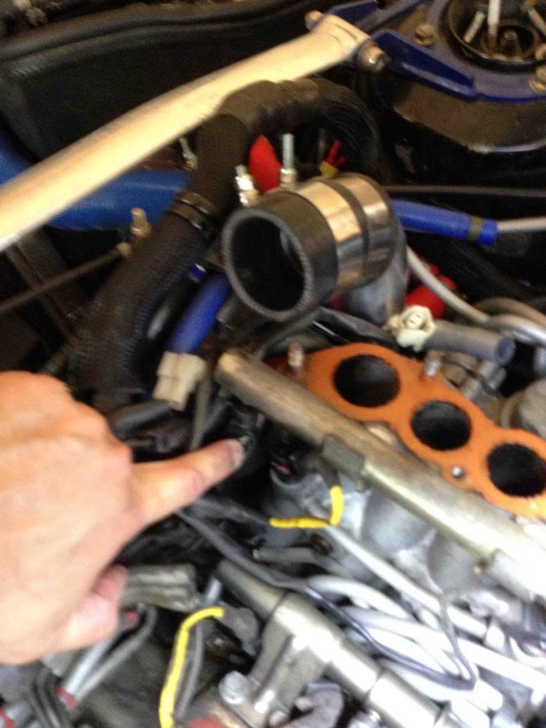
It's not a good picture and I'm pointing to the split fuel line. But if you look towards the bottom you can see the vacuum line that connects the front and back ports on the LIM. And right above the lower fuel rail you can see the four lines exiting the 1-4 splitter and going to the oil injectors.
And just above the oil injector lines you can see the line that originates from the rear top port and then dives down below the lower fuel rail. Where it goes from there I can't say but maybe it'll give you a clue since yours is all opened up.
Hope that helps.
Thread Starter
Joined: Nov 2006
Posts: 2,406
Likes: 2
From: Indiana
I'm fortunate in that I'm rural enough that I don't have echeck! BTW my folks are in Austin visiting fsmily..small world.
I believe I've got my routing worked out. I created the diagram after deciding to delete PRC for fuel. Most diagrams i've seen opt for an oil catch can. I'd like to keep the OEM routing for charcoal canister and PCV.
I have front bottom two ports feeding into the rats nest and going to/from PCV. Front top port goes to pressure sender. Rear top is capped. Large middle to splitter for oil injectors. Rear middle goes to one of the center ports on the LIM.
I think that is all correct but figured i'd get 2nd opinions before I put the UIM back on.

Thread
Thread Starter
Forum
Replies
Last Post
trickster
2nd Generation Specific (1986-1992)
25
Jul 1, 2023 04:40 PM