
S4 Vs. S5 AFM


Thread Starter
Joined: Nov 2002
Posts: 12,752
Likes: 1
From: Laredo, Tx
Hey guys After not being able to sleep last night I was up and chatting with my friend Jon and we were talking about the two styles of AFM's and which was better but we both agreed that we hadn't seen any factual testing on which was better and less of a restriction. After some thought and a cold glass of milk I remembered that I still have the magnehelic hooked up to my Sport that we used to test the stock intake for restriction. This lead me to want to try out and see which AFM creats more of a restriction.
  All I have to do is use a cone filter for ease of swaping and we can test the two after I figure out the re-wire procedure. What do you guys think? I am mainly waiting for NZ and the other smart guys to come up to this thread and see what you think guys. Let me know if its been done before or not so I don't waste my time and gas.
Santiago
PS-Still need to test the damn CAI :-/
I remembered that I still have the magnehelic hooked up to my Sport that we used to test the stock intake for restriction. This lead me to want to try out and see which AFM creats more of a restriction. All I have to do is use a cone filter for ease of swaping and we can test the two after I figure out the re-wire procedure. What do you guys think? I am mainly waiting for NZ and the other smart guys to come up to this thread and see what you think guys. Let me know if its been done before or not so I don't waste my time and gas. Santiago
PS-Still need to test the damn CAI :-/
I'm a boost creep...
Joined: Jan 2002
Posts: 15,608
Likes: 8
From: Auckland, New Zealand
Re: Magnehelic testing!
To get an accurate comparison, you'd need to test both AFM's on the same car, with no changes other than the AFM. Every engine is different (obviously S4 and S5 are), and a different airflow will give a different pressure drop. If you did one test on an S4 car and one on an S5 car you won't know if any difference in reading is because of the AFM or the engine.

Senior Member
Joined: Sep 2003
Posts: 488
Likes: 0
From: Syracuse, New York
What would the results of this test be used for?
Not trying to rain on your parade, I just don't understand what the point would be.
If it was determined that one was better than the other (in terms of flow), you still couldn't use it unless by some amazing stroke of luck it read out the same voltage at the same airflow volume. Otherwise, you'd just be confusing your ECU. I suppose you could compensate with and SAFC, but otherwise you might actually lose horsepower even though you had a more free-flowing intake.
Hmmm....
You would have to test 3 confgurations:
1) Both meters in series. This would give you a good idea how closely the voltage output matched at different airflow volumes
2) S4 only
3) S5 only
The last two would give you an idea of the peak airflow each unit allowed. This would all have to be done on the same car, at the same temperature, etc.
Thread Starter
Joined: Nov 2002
Posts: 12,752
Likes: 1
From: Laredo, Tx
Originally posted by theloudroom
What would the results of this test be used for?
Hmmm....
What would the results of this test be used for?
Hmmm....
Santiago
Senior Member
Joined: Sep 2003
Posts: 488
Likes: 0
From: Syracuse, New York
I still would be interested to see the results of a test with both sensors in series.
This would tell you how close the sensor's outputs matched each other for a given set of conditions, and it would give you a metric to see which flowed better.
This would tell you how close the sensor's outputs matched each other for a given set of conditions, and it would give you a metric to see which flowed better.
Trending Topics
Senior Member
Joined: Sep 2003
Posts: 488
Likes: 0
From: Syracuse, New York
Originally posted by 1987RX7guy
Yeah I will have to figure out how to run the signals into the cabin from both AFMs if I can get them both on there.
Yeah I will have to figure out how to run the signals into the cabin from both AFMs if I can get them both on there.
Thread Starter
Joined: Nov 2002
Posts: 12,752
Likes: 1
From: Laredo, Tx
I have a place to route the wires. But I personally don't know how to re-wire the AFM's to be able to swap them so I will have to do research on that. Unless anyone wants to post up a link or a small "how-to"
Santiago
But I personally don't know how to re-wire the AFM's to be able to swap them so I will have to do research on that. Unless anyone wants to post up a link or a small "how-to"Santiago
Thread Starter
Joined: Nov 2002
Posts: 12,752
Likes: 1
From: Laredo, Tx
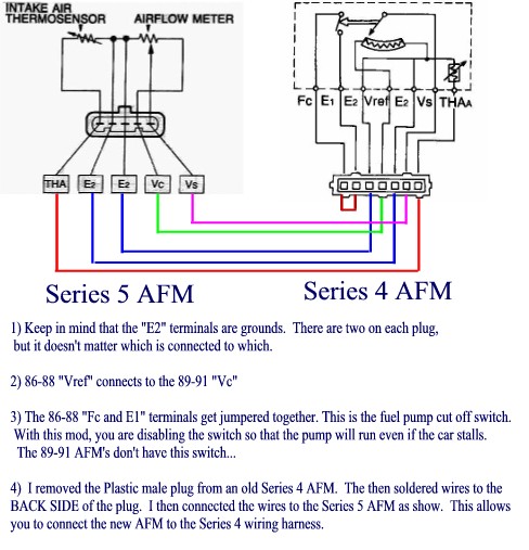
I found this posted in an old thread. Has anyone actually done this with success? It looks simple enough to do with some wire and spade connectors but I thought I would ask for more input.
Santiago

Lives on the Forum
Joined: Feb 2001
Posts: 26,664
Likes: 23
From: n
I still think the Zenki AFM is going to have better flow potential than a Kouki AFM, even though a LOT of people think otherwise.
WHY? At least the Zenki AFM has a *hole in the center*, so airflow potential is most in the center, as dictated by laminar "fluid" dynamics. The Kouki AFM is as big ***** in the center, so all air flow has to move around the center portion.
Go for it!
-Ted
WHY? At least the Zenki AFM has a *hole in the center*, so airflow potential is most in the center, as dictated by laminar "fluid" dynamics. The Kouki AFM is as big ***** in the center, so all air flow has to move around the center portion.
Go for it!
-Ted
Thread Starter
Joined: Nov 2002
Posts: 12,752
Likes: 1
From: Laredo, Tx
This is basically what I want to prove to people and start making things be FACT and not just assumptions based on oppinion. With a magnehelic guage setup and only allowing the AFM to be the variable by retaining as little change or zero change if possible between the runs/tests.
I think the S4 will flow more air.
Santiago
PS-S5 my ***! edit** or should I say vida's ***
With a magnehelic guage setup and only allowing the AFM to be the variable by retaining as little change or zero change if possible between the runs/tests. I think the S4 will flow more air.
Santiago
PS-S5 my ***! edit** or should I say vida's ***
Senior Member
Joined: Sep 2003
Posts: 488
Likes: 0
From: Syracuse, New York
That looks sensible, just make sure you don't accidentally short out the 5V supply from your ECU. That would be bad.
I would also double check this "fuel pump shutoff" swtich comment, as the switch is supposedly off with the AFM closed and on will the AFM fully open (88 FSM page 4A-54). There is no description of the switch's behavior when partway open.
....I just looked at the wiring diagram. The statements about the purpose of that switch are correct. Looks like I'll be jumpering it when I do my MAF conversion.
...oh and you should check the intake temp senor resistances in each FSM to see if they match up.
Thread Starter
Joined: Nov 2002
Posts: 12,752
Likes: 1
From: Laredo, Tx
Yea I am thinking about taking my spare AFM's male S4 plug out and trying to find a burnt up wire harness to get the female plug out of the S5 and make a plug and play dealy.
Santiago
PS- If anyone has a harness that is all burnt but the connector is still good then hit me up with a price.
Santiago
PS- If anyone has a harness that is all burnt but the connector is still good then hit me up with a price.


Joined: Mar 2001
Posts: 31,853
Likes: 3,242
From: https://www2.mazda.com/en/100th/
Originally posted by RETed
I still think the Zenki AFM is going to have better flow potential than a Kouki AFM, even though a LOT of people think otherwise.
WHY? At least the Zenki AFM has a *hole in the center*, so airflow potential is most in the center, as dictated by laminar "fluid" dynamics. The Kouki AFM is as big ***** in the center, so all air flow has to move around the center portion.
Go for it!
-Ted

Thread Starter
Joined: Nov 2002
Posts: 12,752
Likes: 1
From: Laredo, Tx
Originally posted by Wankel7
Sweet to hear it......your gonna do testing and all. Dude, on the next post you need to not use Magnehelic as the subject line. Your gonna confuse people and all.
James
Sweet to hear it......your gonna do testing and all. Dude, on the next post you need to not use Magnehelic as the subject line. Your gonna confuse people and all.
James
Let the uninformed be confused! :p
jk
Yeah I need to ask Icemark to spot me and change the tittle to "S4 Vs. S5 AFM"

Rotary Enthusiast
Joined: May 2001
Posts: 903
Likes: 1
From: Conyngham, PA
Re: Wiring diagram!
Originally posted by 1987RX7guy
I found this posted in an old thread. Has anyone actually done this with success? It looks simple enough to do with some wire and spade connectors but I thought I would ask for more input.
Santiago
I found this posted in an old thread. Has anyone actually done this with success? It looks simple enough to do with some wire and spade connectors but I thought I would ask for more input.
Santiago
*yawn*
I made that wiring diagram about 2 years ago. It works with no ill effects.
I HAVE DYNO PROOF the S5 is better:
Last year I ran my car on the dyno with the S4 AFM and S5 AFM back to back. Same car...same air filter. I ran the S5 AFM first, then the S4, and then back to the S5.
The graphs show that the S5 AFM nets you 1 RWHP. Yeah!
Case closed, next experiment.
I'm a boost creep...
Joined: Jan 2002
Posts: 15,608
Likes: 8
From: Auckland, New Zealand
Don't forget that the S5 AFM's inlet is smaller that the S4's.
S4: 63mm x 50mm = 3150mm�
S5: ~60mm ID (can someone confirm?) = 2827mm�
So the S4's inlet is 11% bigger, which is fairly significant. If you look at the cutaway of the S5 AFM in the FSM you'll see the internal airway isn't exactly huge either.
Personally I wouldn't want to swap to an S5 AFM purely because of losing the fuel pump safety switch. That puppy could save you from going up in flames, so I'd rather keep it.
Last edited by NZConvertible; Jan 29, 2004 at 03:35 PM.
Senior Member
Joined: Sep 2003
Posts: 488
Likes: 0
From: Syracuse, New York
Re: Re: Wiring diagram!
Originally posted by wozzoom
*yawn*
I made that wiring diagram about 2 years ago. It works with no ill effects.
I HAVE DYNO PROOF the S5 is better:
Last year I ran my car on the dyno with the S4 AFM and S5 AFM back to back. Same car...same air filter. I ran the S5 AFM first, then the S4, and then back to the S5.
The graphs show that the S5 AFM nets you 1 RWHP. Yeah!
Case closed, next experiment.
So if one could flow better, but results in a worse air fuel mixture, you'd think it's worse, when really you could do better with the other sensor and a SAFC.
At a minimum, there's a question of whether both sensors read out the same voltage for the same airflow.
Thread Starter
Joined: Nov 2002
Posts: 12,752
Likes: 1
From: Laredo, Tx
Re: Re: Wiring diagram!
Originally posted by wozzoom
*yawn*
I made that wiring diagram about 2 years ago. It works with no ill effects.
I HAVE DYNO PROOF the S5 is better:
Last year I ran my car on the dyno with the S4 AFM and S5 AFM back to back. Same car...same air filter. I ran the S5 AFM first, then the S4, and then back to the S5.
The graphs show that the S5 AFM nets you 1 RWHP. Yeah!
Case closed, next experiment.
*yawn*
I made that wiring diagram about 2 years ago. It works with no ill effects.
I HAVE DYNO PROOF the S5 is better:
Last year I ran my car on the dyno with the S4 AFM and S5 AFM back to back. Same car...same air filter. I ran the S5 AFM first, then the S4, and then back to the S5.
The graphs show that the S5 AFM nets you 1 RWHP. Yeah!
Case closed, next experiment.
Flow and HP are different animals though. :p case not closed!
I'm a boost creep...
Joined: Jan 2002
Posts: 15,608
Likes: 8
From: Auckland, New Zealand
theloudroom is absolutely correct. If swapping on the S5 AFM causes slightly more restriction (less power) but results in slightly leaner mixtures (more power), the result is negligible net change in power, as wozzom's testing showed.
wozzoom, did you compare A/F ratio's as well as power?
wozzoom, did you compare A/F ratio's as well as power?
Last edited by NZConvertible; Jan 29, 2004 at 06:10 PM.

Full Member
Joined: Jan 2003
Posts: 81
Likes: 0
From: Ottawa
I would be VERY much interested in knowing the real voltage difference between the two styles AFM rather than the flow potential. By voltage difference I mean the curve of Voltage output vs Airflow. Anybody ever did that? Like mentionned before, if we applies aerodynamics basics, well the S4 has a better flow potential. Another interesting point also is the "adjustability" of the flapper style AFM, which the cone style does not offer.