
S4 TII - Turbocharger, LIM removal and replacement

S4 TII - Turbocharger, LIM removal and replacement
I'm replacing my Throttle body, UIM, LIM and turbocharger and figured I'd post some pics for ya.
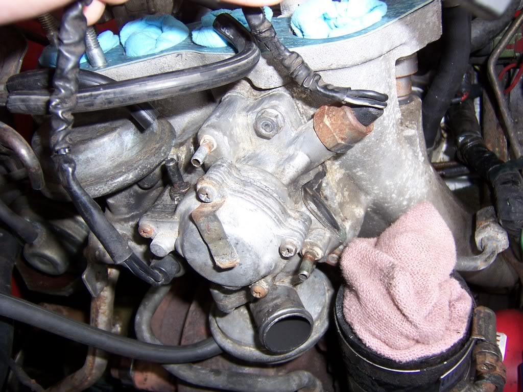
So basically, I removed the intercooler,
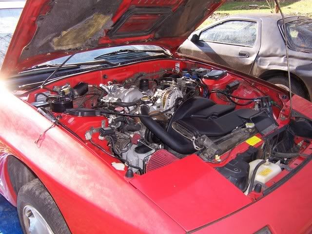
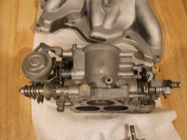
TB and UIM.
The the air pump and turbo inlet duct, then removed the fuel rails, disconnected the injectors and plugged the hoses and holes in the block for the injectors.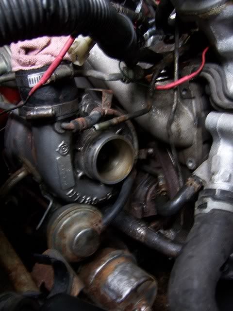
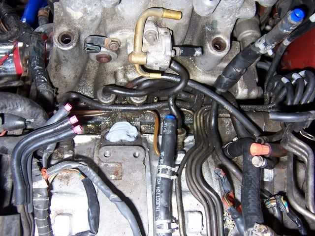
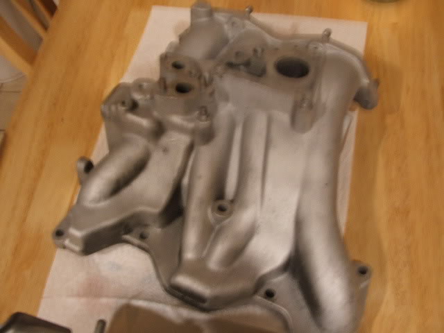
I am going to be redoing my oil metering injector lines plus the vac spider that connects them to the UIM.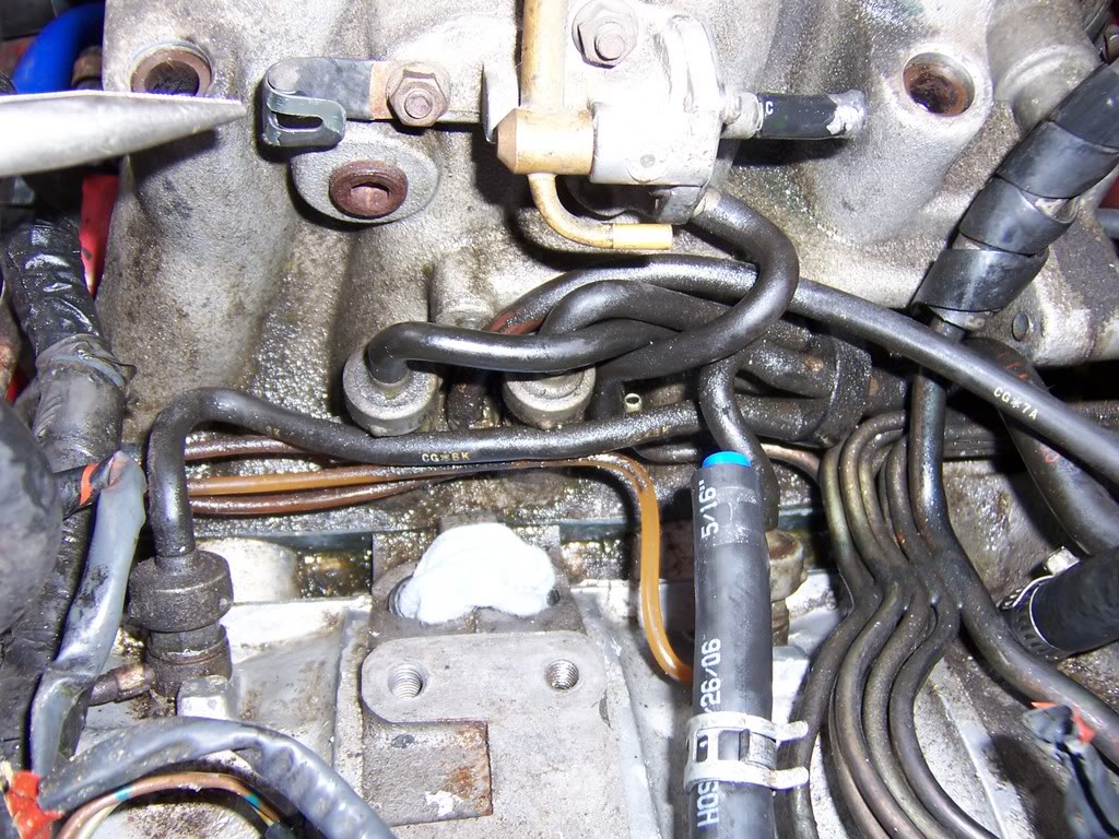
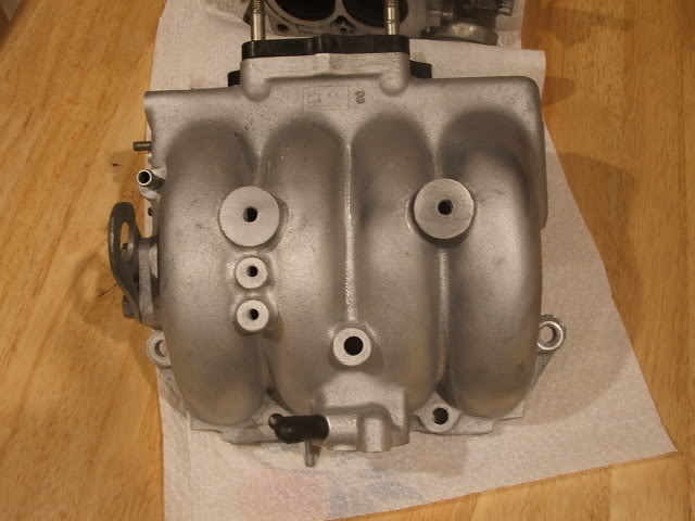
The acv valve, split air tube and vac hoses were removed.
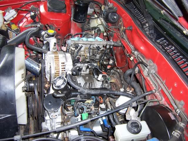
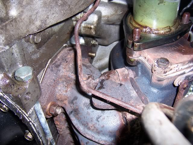
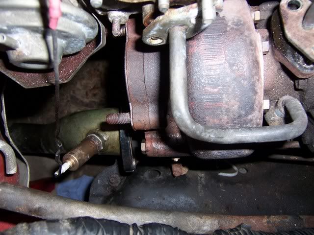
I felt that it would be easiest to take the turbo out first rather than the LIM, so I disconnected the coolant lines and the oil lines on the turbo.
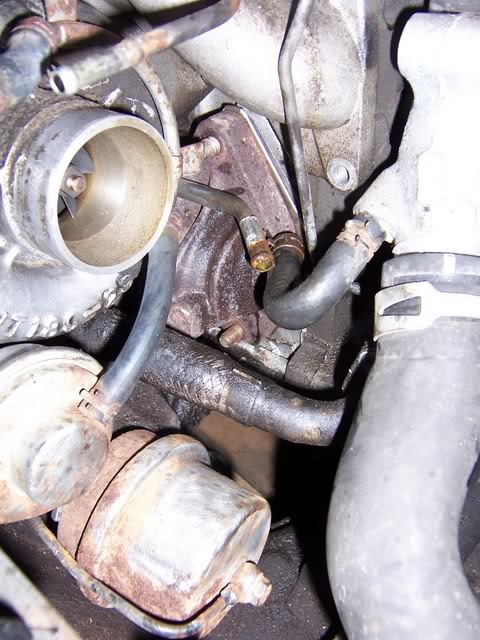
Unhook the waste gate actuator line as well.
Then the bolts for the turbo manifold to engine block were removed as well as the bolts holding the down pipe on to the turbo.
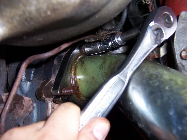
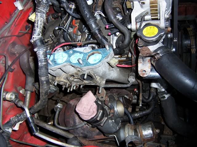
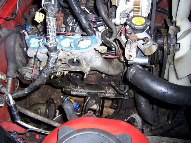
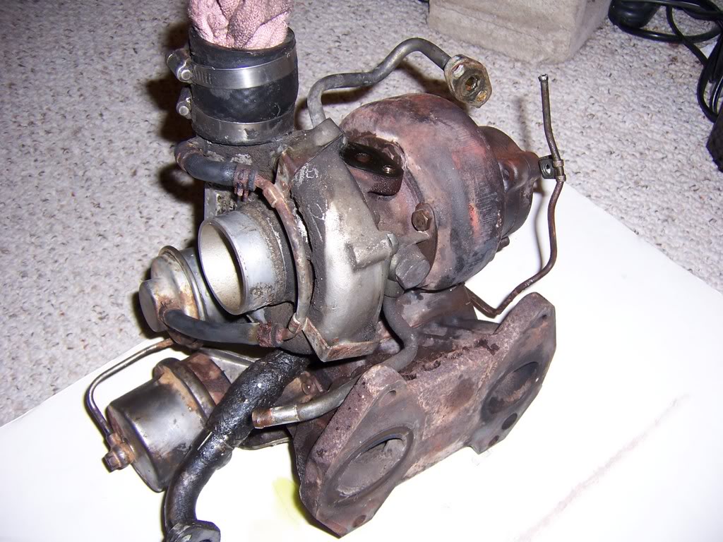
It was pouring rain by this point, so I had to stop here, but next would be to unbolt the lower intake manifold and then start the installs. I'll post the removal and install of the LIM and everything later, the turbo still has to be sent to BNR....
new parts:
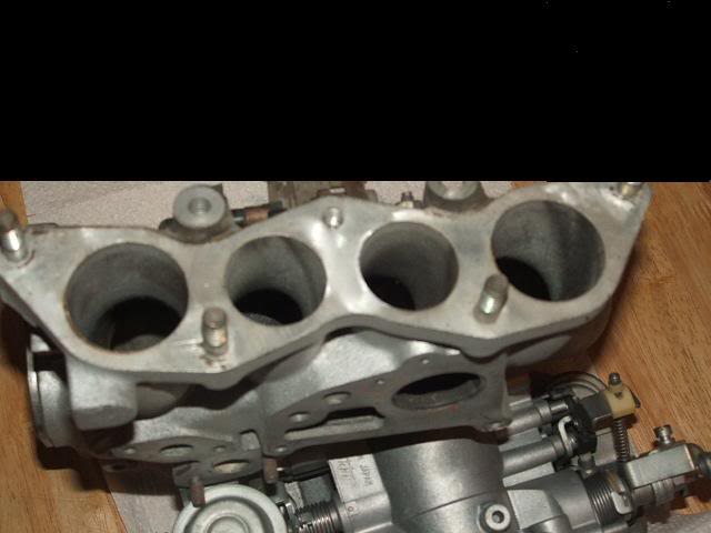
So basically, I removed the intercooler,
TB and UIM.
The the air pump and turbo inlet duct, then removed the fuel rails, disconnected the injectors and plugged the hoses and holes in the block for the injectors.
I am going to be redoing my oil metering injector lines plus the vac spider that connects them to the UIM.
The acv valve, split air tube and vac hoses were removed.
I felt that it would be easiest to take the turbo out first rather than the LIM, so I disconnected the coolant lines and the oil lines on the turbo.
Unhook the waste gate actuator line as well.
Then the bolts for the turbo manifold to engine block were removed as well as the bolts holding the down pipe on to the turbo.
It was pouring rain by this point, so I had to stop here, but next would be to unbolt the lower intake manifold and then start the installs. I'll post the removal and install of the LIM and everything later, the turbo still has to be sent to BNR....
new parts:
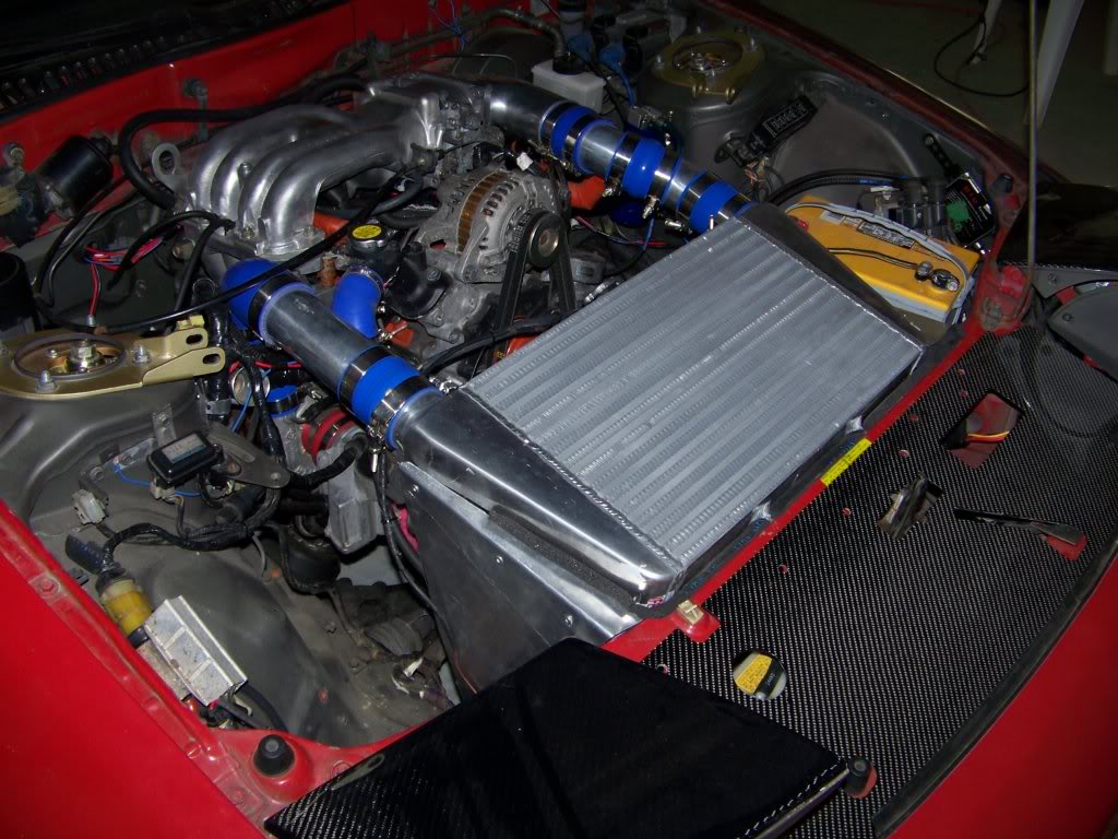
what kind of hp are you getting with that setup?? "87 TII- Rebuilt w/Rtek7 2.1, BNR Stg 1, Profec B Spec 2, 4x720cc, 255lph pump, RB DP w/3" turboback, NGK A/Fx, Stance GR+, VMIC, etc..."
I haven't taken it to a dyno and don't plan on it either but it's probably around 300 at 12psi. Hoping for around 315hp at 15psi... this is what I have seen in other similar setups, though I haven't seen any done with the FD manifolds and VMIC like mine, hoping maybe I can get a few more horse from the better airflow and cooling.
As of now:
As of now:
Nice setup. It's reminiscent of BlueTII's setup. I just saw his (BlueTII's) setup in person out at the last street legal drags up here and it is BE-A-UTIFUL! Looks very nice though good work. Where do you have your air filter going to?
Thanks. Yeah BlueTII's was a big inspiration for me. At this point I just have a screen over the AFM inlet, can't really fit a big filter on the way it sits now. I'd like to pipe it out from behind the radiator though, my AITs don't seem to mind the initial hot air though. The cold side pipes are cold to the touch even after a nice drive.
If you don't mind could you post up an Rtek log so I can compare my AITs to yours. I really wanted to do a VMIC setup like that but I am very happy so far with my H-FMIC except for the slight boost pressure loss. I just need to step up to the BNR stage 3 then all will be good.
Trending Topics
The FD TPS was wired using only the narrow range signal like the FC TPS, there are wiring pin diagrams for the FD TPS on here in some of my other threads if you want to search for them.

Thread
Thread Starter
Forum
Replies
Last Post
Turblown
Vendor Classifieds
0
Aug 18, 2015 10:01 PM
KAL797
Test Area 51
0
Aug 11, 2015 03:47 PM