
It Runs! Pics and Vids Of My Turbo-NA-Bridgeport Project

Thread Starter
Joined: Feb 2001
Posts: 29,798
Likes: 128
From: London, Ontario, Canada
It Runs! Pics and Vids Of My Turbo-NA-Bridgeport Project
I'm sad to say that this will be the last installment for a while concerning my ongoing project. For you see, there's not really a lot for me to do right now. The weekend of Sept. 17th was a major turning point in that I started the car for the first time. Therefore, at the moment, all I can do is drive and tune it until the engine is broken in...But I'm getting ahead of myself.
This as you may have guessed is my latest thread on my ongoing turbo-NA-bridgeport project. The last (and very entertaining) thread can be found here.
This thread contains the final 49 pictures leading up to the first startup of the engine. At the end, you will find the associated videos. PLEASE read the entire thread before downloading the videos! It will set you up for what you see on the video. There's a lot of info here so as pretty as the pictures are, it's important to read the text that goes along with them as it almost always explains why I did something the way I did, made a particular choice, etc. Creative criticisms are always appreciated, flames and insults are not.
That said, lets get down to the good stuff.
We last left off painting the catback. I used POR-20 high temp paint to give the full stainless exhaust that sort of silver-aluminum look. Also it will help keep rust off the welds.

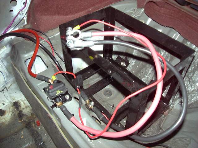
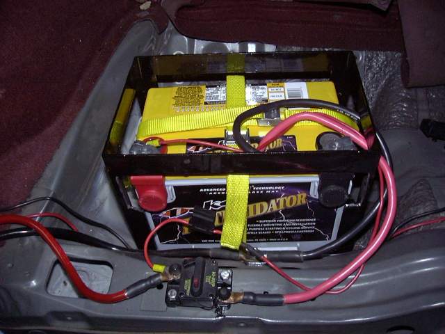
With the exhaust drying (the drying process for POR-20 is truly bizarre) I was in a bit of a wiring mood so I set up the breaker and battery cables. The breaker is a 150 AMP Cooper-Bussmann unit that I have had good success with in other cars. Even though it's rated at 150A, it will stand up to excessive cranking just fine (I've never popped one doing so) yet still trip in the event of a direct short. Thankfully I have never had to test that. The breaker also includes a manual trip switch to cut all power to the car. Those who know what the fuse is bypassing the breaker will know that it is an important security measure. The rest of you can figure it out on your own.
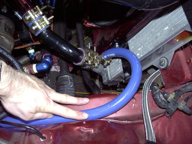
With the spectacular failure of my copper heater pipes, I needed some kind of heater hose. The stock hose had caused no end of problems for me because no matter how new it was, no matter how careful I was to keep oil off of it and not over tighten the clamp, it failed about once a year. You can only be stranded at the side of the road a few times before you start thinking of ways to eliminate the problem. So the hose I used is a silicone based hose made by Thermopol. It is not the least bit cheap but it's thick high temperature silicone and internal fibre braiding mean that it will probably last the life of the vehicle. Of course, the hose clamps are T-bolt style.
Here's the passenger side heater hose as it connects to the rad.
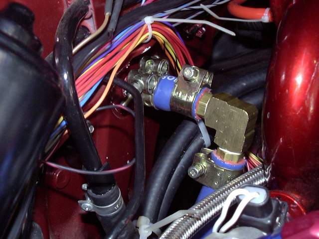
And the connection at the firewall. The tight fit required a 90 degree fitting. I purchased some large brass nipples and 90 degree threaded el from the local hydraulic store. Yes, there's a paint chip in my manifold. Damn...
This as you may have guessed is my latest thread on my ongoing turbo-NA-bridgeport project. The last (and very entertaining) thread can be found here.
This thread contains the final 49 pictures leading up to the first startup of the engine. At the end, you will find the associated videos. PLEASE read the entire thread before downloading the videos! It will set you up for what you see on the video. There's a lot of info here so as pretty as the pictures are, it's important to read the text that goes along with them as it almost always explains why I did something the way I did, made a particular choice, etc. Creative criticisms are always appreciated, flames and insults are not.
That said, lets get down to the good stuff.
We last left off painting the catback. I used POR-20 high temp paint to give the full stainless exhaust that sort of silver-aluminum look. Also it will help keep rust off the welds.
With the exhaust drying (the drying process for POR-20 is truly bizarre) I was in a bit of a wiring mood so I set up the breaker and battery cables. The breaker is a 150 AMP Cooper-Bussmann unit that I have had good success with in other cars. Even though it's rated at 150A, it will stand up to excessive cranking just fine (I've never popped one doing so) yet still trip in the event of a direct short. Thankfully I have never had to test that. The breaker also includes a manual trip switch to cut all power to the car. Those who know what the fuse is bypassing the breaker will know that it is an important security measure. The rest of you can figure it out on your own.
With the spectacular failure of my copper heater pipes, I needed some kind of heater hose. The stock hose had caused no end of problems for me because no matter how new it was, no matter how careful I was to keep oil off of it and not over tighten the clamp, it failed about once a year. You can only be stranded at the side of the road a few times before you start thinking of ways to eliminate the problem. So the hose I used is a silicone based hose made by Thermopol. It is not the least bit cheap but it's thick high temperature silicone and internal fibre braiding mean that it will probably last the life of the vehicle. Of course, the hose clamps are T-bolt style.
Here's the passenger side heater hose as it connects to the rad.
And the connection at the firewall. The tight fit required a 90 degree fitting. I purchased some large brass nipples and 90 degree threaded el from the local hydraulic store. Yes, there's a paint chip in my manifold. Damn...
Thread Starter
Joined: Feb 2001
Posts: 29,798
Likes: 128
From: London, Ontario, Canada
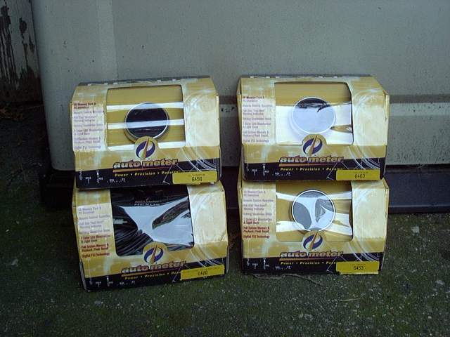
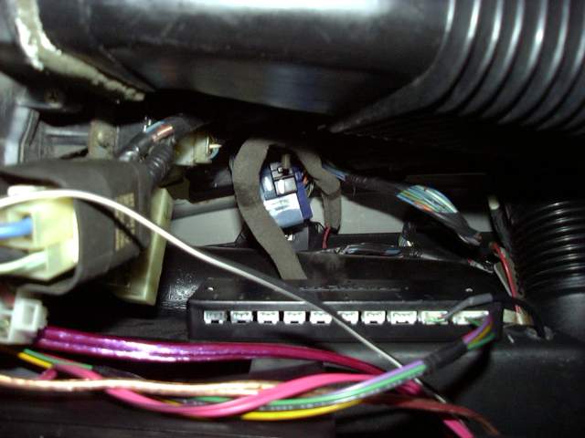
The gauges I chose are AutoMeter's new Nexus line. I first saw these things demonstrated by AutoMeter at Detroit AutoRama 2005. The moment I saw them, I knew that they were the perfect gauge for the RX-7. These gauges are AutoMeter's first really new gauge in a long time. They are all fully electrical, with modern senders and a central control box. Not only does this allow fancy (though kind of useless) things like 7 colour lighting, custom startup and shutdown sequences, demo mode and a few other goodies, but it allows truly useful additions like data logging and a massive reduction in the amount of wires going to each gauge. All the senders connect to the control box, and then a single cable leads from the box to the first gauge. This cable carries power, ground and signal to the gauge. Each successive gauge then plugs into the previous gauge. The three gauges shown here are the "secondary" gauges; oil temp and pressure, and fuel pressure.
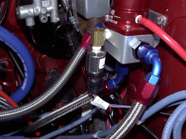
The first task was to mount the fuel pressure sender. The Aeromotive regulator provides a 1/8" NPT fuel pressure port so it was a simple matter to attach the sender using a 90 degree fitting. The 90 degree turn prevents the sender from sticking far into the engine bay. Notice the new style sender with proper WeatherPack style connectors. Kudos to Autometer for making the right choice for hookup, and including a small tube of dielectric grease with every gauge.
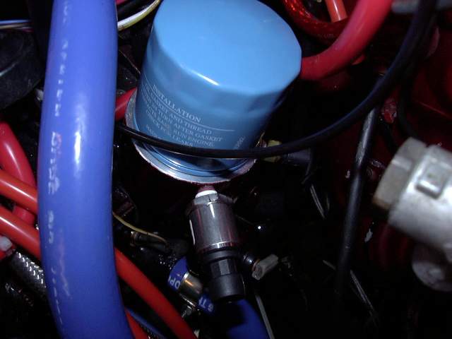
Next the senders for the oil pressure and temperature gauges were installed. Again they just screwed into the 1/8" NPT ports provided on the Speed Machine oil pedistole. A little Teflon sealing compound prevents leaks down the threads. At the same time I disassembled the WeatherPack connectors, packed them with dielectric grease, then reassembled.
The control box comes with a remote to operate it's functions, but I didn't want it stuck to the dash somewhere. So the glove box was an ideal location. Velco strips hold it to the side.
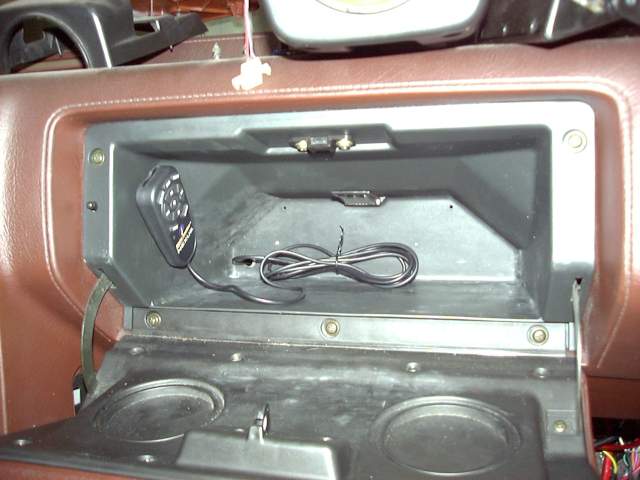
There's actually a lot of space behind the glove box and it seemed like a perfect location for the Nexus control box. Mounting it was easy as there are provided screw holes and self-tapping screws included. The two harnesses that plug into it are for the power/ground/IGN/RPM hookup (it also has a tach out feature) and remote.
The first task was to mount the fuel pressure sender. The Aeromotive regulator provides a 1/8" NPT fuel pressure port so it was a simple matter to attach the sender using a 90 degree fitting. The 90 degree turn prevents the sender from sticking far into the engine bay. Notice the new style sender with proper WeatherPack style connectors. Kudos to Autometer for making the right choice for hookup, and including a small tube of dielectric grease with every gauge.
Next the senders for the oil pressure and temperature gauges were installed. Again they just screwed into the 1/8" NPT ports provided on the Speed Machine oil pedistole. A little Teflon sealing compound prevents leaks down the threads. At the same time I disassembled the WeatherPack connectors, packed them with dielectric grease, then reassembled.
The control box comes with a remote to operate it's functions, but I didn't want it stuck to the dash somewhere. So the glove box was an ideal location. Velco strips hold it to the side.
There's actually a lot of space behind the glove box and it seemed like a perfect location for the Nexus control box. Mounting it was easy as there are provided screw holes and self-tapping screws included. The two harnesses that plug into it are for the power/ground/IGN/RPM hookup (it also has a tach out feature) and remote.
Thread Starter
Joined: Feb 2001
Posts: 29,798
Likes: 128
From: London, Ontario, Canada
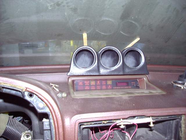
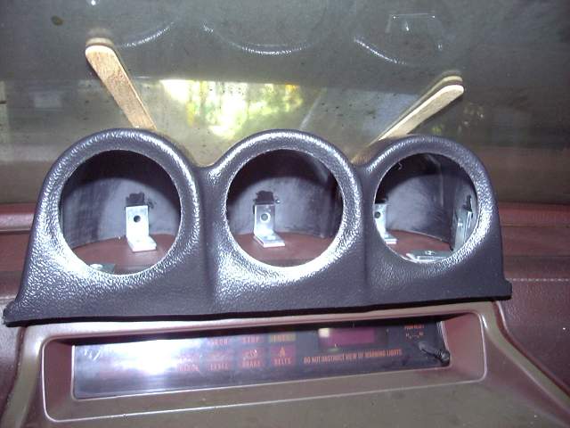
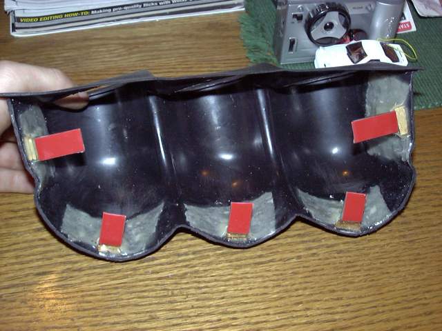
One of my major annoyances when I see any kind of modded cars are gauges strewn about the cabin, gauges in the way of other gauges, or previous features (like idiot light clusters) removed to make way for gauges. Because of this I knew that I wanted to mount my secondary gauges in a way that will not interfere with another function, still be visible at a glance when driving, but not intrude into my primary field of vision. No one seems to make any gauge pods for the RX-7 besides the A-pillar pods and I already have one of those. Well there's also an idiot light cluster pod but because it replaces the idiot cluster it is not an option for me. After a little digging I found a generic APC 3 gauge pod that is almost the exact width of the idiot cluster. Trimming about 1/4" off the bottom allowed it to fit snug to the dash with about 1/8" between it's top and the windshield. Popsicle sticks hold it in place temporarily while I test the fit.
Mounting was accomplished with angle irons and 3M double sided trim tape. The angle irons attach to the inside of the pod and then get stuck to the dash. This tape is STRONG after it has cured and WILL NOT COME OFF a properly prepared surface.
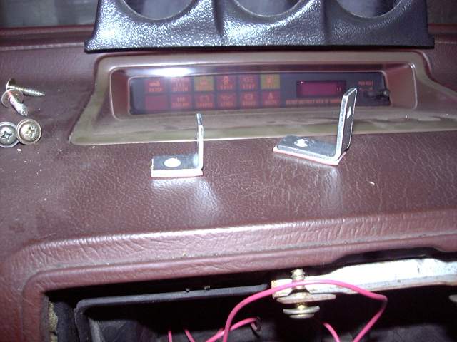
The pod was put into place and a small amount of epoxy used to "tack" the brackets where they needed to go.
I wanted to get the car off the ramps and onto it's wheels, so I pushed it out onto the driveway and installed the catback. It fit up perfectly which was a bit of a surprise for me. Everything tends to move a little between the tacking and finish welding stages, and a millimeter of movement at one end of the exhaust means a few centimeters of movement at the other. This I assume is why most exhaust is assembled in pieces (well, that and shipping). There were no fitment issues and the pipes and mufflers ended up exactly where they were during the initial mockup. Once things were tightened down, the system was solid and rattle free.
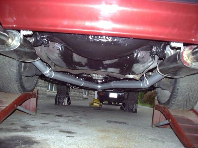
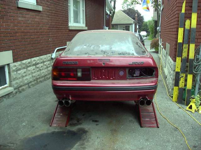
The mufflers sat even at the back of the car with exactly the right distance from the bumper. I'm very happy with the way the exhaust turned out. Say what you want about my mufflers, but I like them.
Mounting was accomplished with angle irons and 3M double sided trim tape. The angle irons attach to the inside of the pod and then get stuck to the dash. This tape is STRONG after it has cured and WILL NOT COME OFF a properly prepared surface.
The pod was put into place and a small amount of epoxy used to "tack" the brackets where they needed to go.
I wanted to get the car off the ramps and onto it's wheels, so I pushed it out onto the driveway and installed the catback. It fit up perfectly which was a bit of a surprise for me. Everything tends to move a little between the tacking and finish welding stages, and a millimeter of movement at one end of the exhaust means a few centimeters of movement at the other. This I assume is why most exhaust is assembled in pieces (well, that and shipping). There were no fitment issues and the pipes and mufflers ended up exactly where they were during the initial mockup. Once things were tightened down, the system was solid and rattle free.
The mufflers sat even at the back of the car with exactly the right distance from the bumper. I'm very happy with the way the exhaust turned out. Say what you want about my mufflers, but I like them.
Thread Starter
Joined: Feb 2001
Posts: 29,798
Likes: 128
From: London, Ontario, Canada
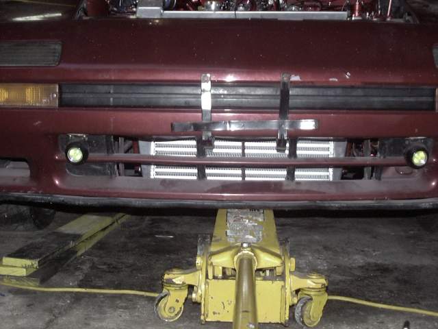
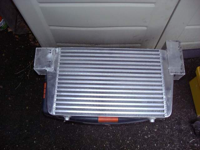
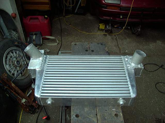
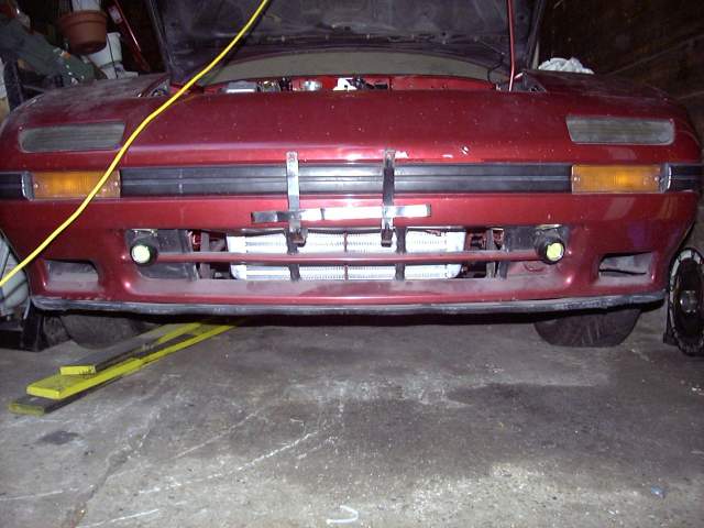
Now I could move to the front of the car and get working on the intercooler. The cooler I chose is about 14" in height by 26" in length (tank to tank) and 3" thick. I probably could have gone one size up in length but it would have meant having to cut the car which is something I wanted to avoid. In the future, the car will go back to NA at one point and I didn't want big chunks cut out of the car for nonexistent intercooler piping. I also wanted to go through the rad supports and not under the headlights. Not only would this mean something like 5 feet less of piping, but it means fewer bends and not having to ditch the washer fluid reservoir in the lower front drivers fender.
To mount the top of the cooler I just made two "L" shaped brackets out of 3MM thick steel. Holes were drilled into the radiator crossmember to secure them with bolts.
The bottom of the cooler was supported with another set of brackets made from the same steel as the top and a little angle iron. Here they are just tacked. The car-side of the brackets attach to two M8 nuts that are already on the frame rail between it and the bumper. I'm not sure what Mazda intended them for, but there are two on each side which are prefect for intercooler brackets. The intercooler mounted just a little higher then normal because I have a habit of bumping things with the bottom of the bumper and I would hate to mess up the intercooler.

To fully adhere the mounting brackets to the gauge pod, I mixed up a batch of epoxy and used it to soak a cloth mesh. This made a sort of "fiberglass" which then was laid over the brackets and onto the gauge pod. The space between the brackets and pod was then filled with wood and epoxy. Once dried, this became super strong. In fact I could bend the entire dash up by pulling on the pod once the 3M tape had set.
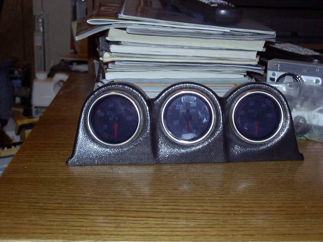
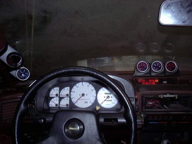
Once the epoxy was dry I installed and fine tuned the position of the gauges. From left to right we have oil pressure, oil temperature and fuel pressure.
To mount the top of the cooler I just made two "L" shaped brackets out of 3MM thick steel. Holes were drilled into the radiator crossmember to secure them with bolts.
The bottom of the cooler was supported with another set of brackets made from the same steel as the top and a little angle iron. Here they are just tacked. The car-side of the brackets attach to two M8 nuts that are already on the frame rail between it and the bumper. I'm not sure what Mazda intended them for, but there are two on each side which are prefect for intercooler brackets. The intercooler mounted just a little higher then normal because I have a habit of bumping things with the bottom of the bumper and I would hate to mess up the intercooler.
To fully adhere the mounting brackets to the gauge pod, I mixed up a batch of epoxy and used it to soak a cloth mesh. This made a sort of "fiberglass" which then was laid over the brackets and onto the gauge pod. The space between the brackets and pod was then filled with wood and epoxy. Once dried, this became super strong. In fact I could bend the entire dash up by pulling on the pod once the 3M tape had set.
Once the epoxy was dry I installed and fine tuned the position of the gauges. From left to right we have oil pressure, oil temperature and fuel pressure.
Thread Starter
Joined: Feb 2001
Posts: 29,798
Likes: 128
From: London, Ontario, Canada
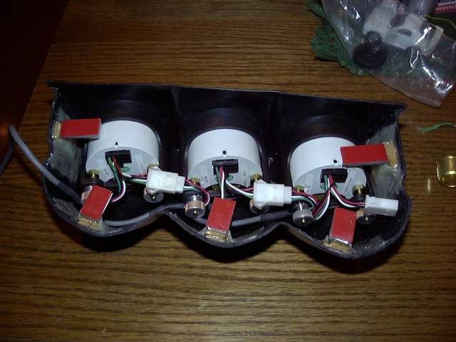
As I mentioned, one of the advantages of the Nexus gauges is the wiring harness. Each gauge plugs into the bus, which then leads back to the central control box. In this way the mess of wiring and tubing that normally leads to a gauge pod is avoided. There are no messy and dangerous fluid leaks into the cabin, and the gauges are totally isolated from any badness the occurs in the engine bay.
The gauge pod is still going to need a little bit of work to make it fit the dash perfectly. A litle bit of felt around the edges will probably clean up the pod and make it look close to factory.
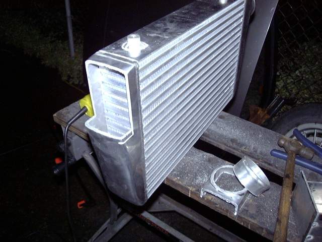
Back to the intercooler. The stock inlets and outlets run in the wrong direction for how I wanted to mount the cooler so I needed to modify the end tanks. The inlet needed to go into the passenger side tank at about a 90 degree angle, and the outlet needed to exit the drivers tank at about 45 degrees.
The solution was to build two small tank extensions out of aluminum and replace the existing inlets and outlets. I cut the tank sections then tacked them together.
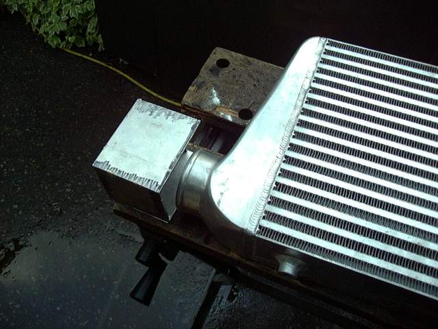
Time to ruin a perfectly good intercooler! Out came the cutting wheel and safety glasses. A few minutes of work with the angle grinder and the deed was done.
The tank extension fit fine though some filing would be necessary before it was welded in place.
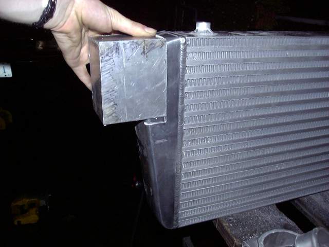
The drivers side was cut in the same way, but a little larger to allow for fitting of the angled outlet pipe.
The gauge pod is still going to need a little bit of work to make it fit the dash perfectly. A litle bit of felt around the edges will probably clean up the pod and make it look close to factory.
Back to the intercooler. The stock inlets and outlets run in the wrong direction for how I wanted to mount the cooler so I needed to modify the end tanks. The inlet needed to go into the passenger side tank at about a 90 degree angle, and the outlet needed to exit the drivers tank at about 45 degrees.
The solution was to build two small tank extensions out of aluminum and replace the existing inlets and outlets. I cut the tank sections then tacked them together.
Time to ruin a perfectly good intercooler! Out came the cutting wheel and safety glasses. A few minutes of work with the angle grinder and the deed was done.
The tank extension fit fine though some filing would be necessary before it was welded in place.
The drivers side was cut in the same way, but a little larger to allow for fitting of the angled outlet pipe.
Thread Starter
Joined: Feb 2001
Posts: 29,798
Likes: 128
From: London, Ontario, Canada
The drivers side tank extension looks a little weird but the extra height was necessary as there was no way to predict where the pipe would end up until the intercooler was modified and mounted in place.
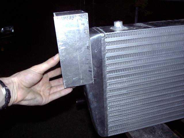
The tanks were then tacked together so the cooler could be fitted to the car.
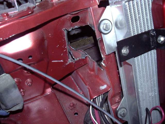
Once the cooler was in place I could cut a hole in the drivers side radiator support for the intercooler piping. There's actually quite a lot of space available here if you are willing to go through on an angle so 2.5" piping easily fits. I found that the angle grinder was not a very good tool for this after cutting myself pretty badly several times. Oddly enough the Dremel tool with cutting disks was quicker. While it cut slower, it was far easier to maneuver around and not nearly as scary. The hole is a little rough right now but during the winter I'll finish it off and trim the edges with rubber.
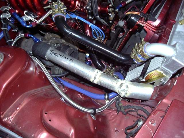
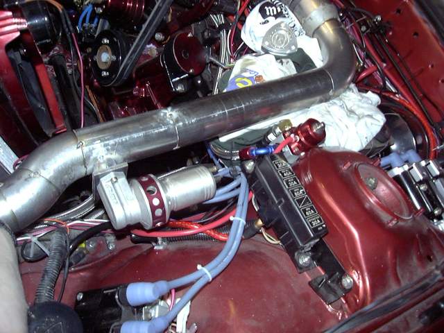
Because the stock turbo is just temporary (I'm just using it for the break in to avoid having to fab a new manifold and allow me to drive the car) I didn't waste much time on the piping. This thing took all of about half an hour and was made from scrap tubing. I used a little 2" exhaust tubing, some 2" stainless tubing and some spare 2.5" galvanized tubing that I had lying around. This, my friends, is ghetto. But it will do the job until I upgrade the turbo. A little silver paint will clean it up. You can also see that the heater hose has been secured with clamps and the temporary intercooler pipe leaves plenty of room for the TID.
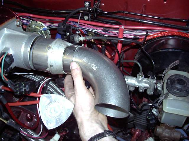
Now I could start the drivers side piping. The outside diameter of the throttle body is about 3.25" so I needed to start with a small section of 3" stainless tube to provide a clamping surface for the silicone coupler. From there, a 3" to 2.5" thick SCH 10 stainless transition connects to a sort section of 2.5" stainless tube, then a 90 degree stainless el. I used a thick SCH 10 transition so that I had enough thickness to drill and tap for 1/8" NPT to install as set of nipples for fresh air connections to the injector air bleeds, metering oil nozzles and purge valve. Everything is just being tacked for now for final welding later. To connect the pipe to the throttle body, I purchased a 3" to 3.25" silicone transition coupler.
The tanks were then tacked together so the cooler could be fitted to the car.
Once the cooler was in place I could cut a hole in the drivers side radiator support for the intercooler piping. There's actually quite a lot of space available here if you are willing to go through on an angle so 2.5" piping easily fits. I found that the angle grinder was not a very good tool for this after cutting myself pretty badly several times. Oddly enough the Dremel tool with cutting disks was quicker. While it cut slower, it was far easier to maneuver around and not nearly as scary. The hole is a little rough right now but during the winter I'll finish it off and trim the edges with rubber.
Because the stock turbo is just temporary (I'm just using it for the break in to avoid having to fab a new manifold and allow me to drive the car) I didn't waste much time on the piping. This thing took all of about half an hour and was made from scrap tubing. I used a little 2" exhaust tubing, some 2" stainless tubing and some spare 2.5" galvanized tubing that I had lying around. This, my friends, is ghetto.
But it will do the job until I upgrade the turbo. A little silver paint will clean it up. You can also see that the heater hose has been secured with clamps and the temporary intercooler pipe leaves plenty of room for the TID.Now I could start the drivers side piping. The outside diameter of the throttle body is about 3.25" so I needed to start with a small section of 3" stainless tube to provide a clamping surface for the silicone coupler. From there, a 3" to 2.5" thick SCH 10 stainless transition connects to a sort section of 2.5" stainless tube, then a 90 degree stainless el. I used a thick SCH 10 transition so that I had enough thickness to drill and tap for 1/8" NPT to install as set of nipples for fresh air connections to the injector air bleeds, metering oil nozzles and purge valve. Everything is just being tacked for now for final welding later. To connect the pipe to the throttle body, I purchased a 3" to 3.25" silicone transition coupler.
Thread Starter
Joined: Feb 2001
Posts: 29,798
Likes: 128
From: London, Ontario, Canada
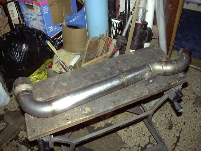
A weld el was cut to 3 random angles and recombined to form a curve that leads from the intercooler outlet pipe and up to the el coming from the throttle body. The long pipe between was done in two sections to provide a very slight (one or two degrees) bend for final alignment.

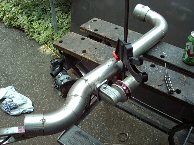
Here's the finished pipe tacked together.
A 1" hole saw cut through the stainless to make a mounting area for the BOV. Using a short section of 1" tubing I tacked on the flange while keeping the BOV level. I would have much preferred to mount the BOV closer to the throttle body but there was simply not enough space available to do so.
The pipe was then laid into the engine bay to check the final fit before it finish welded.
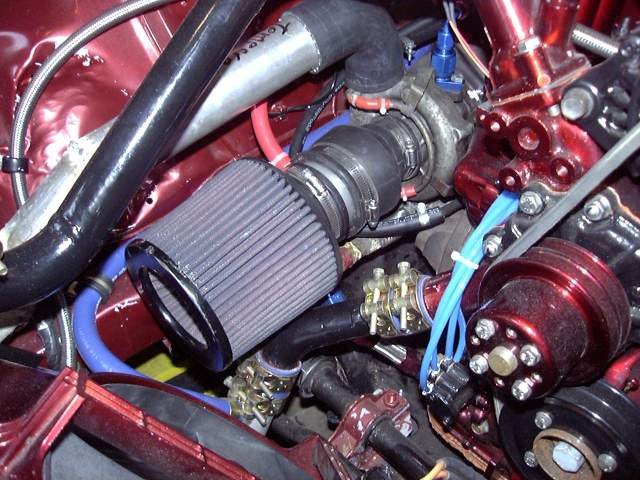
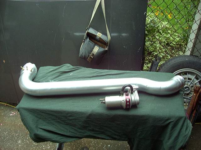
It only took a few minutes to make the turbo inlet duct. It's made of a 2.25" to 3" plumbing coupler and a small section of 3" aluminum tubing. The red vacuum hose connects to a nipple and leads over to the charcoal canister. That is the only part of the stock emissions system I retained because I can't stand oil catch cans and don't want the car to reek like fuel from an open vented fuel tank.
Here's the finished pipe tacked together.
A 1" hole saw cut through the stainless to make a mounting area for the BOV. Using a short section of 1" tubing I tacked on the flange while keeping the BOV level. I would have much preferred to mount the BOV closer to the throttle body but there was simply not enough space available to do so.
The pipe was then laid into the engine bay to check the final fit before it finish welded.
It only took a few minutes to make the turbo inlet duct. It's made of a 2.25" to 3" plumbing coupler and a small section of 3" aluminum tubing. The red vacuum hose connects to a nipple and leads over to the charcoal canister. That is the only part of the stock emissions system I retained because I can't stand oil catch cans and don't want the car to reek like fuel from an open vented fuel tank.
Trending Topics
Thread Starter
Joined: Feb 2001
Posts: 29,798
Likes: 128
From: London, Ontario, Canada
The battery I chose for the car is the Deka Intimidator. This battery is an 850 CCA 55AH AGM monster that has been well proven in electric vehicle racing. In fact tests have shown this battery capable of producing nearly 3000A into a direct short without any long term damage. It is a deep cycle battery in standard group 34 size, with both top and side terminals. Deka has abandoned the "spiral cell" technology because they can pack more lead (and thus more AHs) into a standard square formfactor. I chose to use the top terminals since they are capable of carrying more current then side terminals. My only annoyance is that the spec sheet that I originally referenced when I designed the battery tray did not account for the size of the side terminals so some adjustment of the box was necessary to make the battery fit. The yellow straps are something I picked up at the local tow truck store. They are designed to secure vehicles to flatbeds and are rated at 1200 LBs each. Just after installation I immediately charged the battery to 14.9V so it would stay nice and fresh.
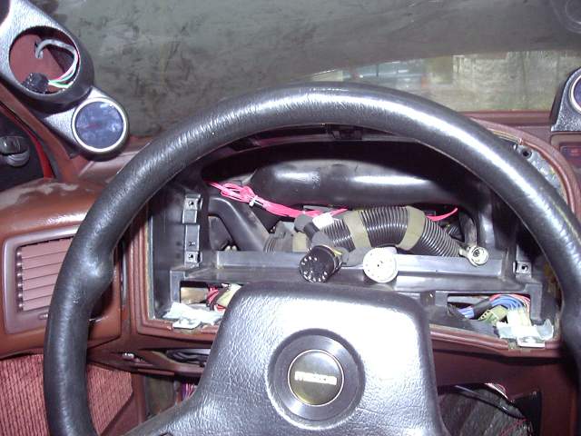
My Nexus boost gauge arrived so I needed to get it's GM style MAP sensor installed. Because I already had a vacuum line leading into the cabin for the Microtech's MAP sensor, I made a bracket to install the new MAP sensor in place of the factory atmospheric pressure located in the passenger kick panel. The vacuum line from the engine bay then Ts to connect to the Microtech and Nexus MAP sensor. Note that these sensors must be mounted with the vacuum port facing downwards to prevent contamination from condensation. Interestingly, that bracket was made from a bit of scrap metal that I had laying around. In it's previous life it was the battery retaining bracket in an APC 800RT computer UPS.

The boost gauge fit into the existing A-pillar pod. I ran the bus cable from the secondary Nexus gauges through the instrument cluster opening and up the pillar. I did have to extend the harness somewhat since the Nexus control box only comes with one long cable as they assume all your gauges will be mounted side by side. The empty opening in the pod is for the wideband which will be installed after the initial rough tune. Again, it is Nexus and will connect to the bus cable sitting in the pod. I'll add a single pod later on to house the Nexus water temp gauge and just continue the bus. These gauges are so easy and neat to wire that it is a joy hooking them up.
Now that I had the battery and all the electrical connected, I couldn't resist powering up the car. With a fire extinguisher handy I hit the main breaker and set the key to "RUN". The Nexus gauges powered up and the electrical system of the car sprang to life. Quick checks confirmed that all the stock systems (headlights, wipers, heater, etc.) worked fine, and the Microtech showed that all sensors were reading properly. I then went through the TPS calibration procedure (very easy with any standalone) and set the trigger temperature for the e-fan. A car with a new electrical system certainly is a pleasure! Even under full load the Intimidator refused to drop below 13.5V while cranking and none of the dash or headlights dimmed when other accessories were switched on. Exactly what I wanted.
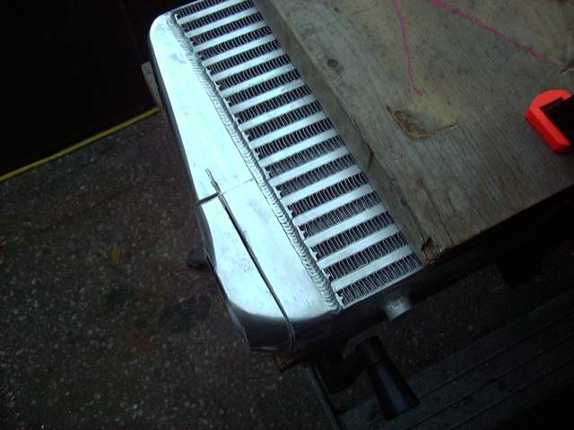
With the electrical side ready to go, it was time to finish welding the intercooler. I'd like to thank CP Racing for letting me have a few hours on their TIG welder continuously contaminating and having to regrind their tungstens. TIG welding aluminum is a challenge but after a few hours I was making some nice beads with solid penetration. Yeah, the modified end tanks look a little strange but that's just aesthetic.
My Nexus boost gauge arrived so I needed to get it's GM style MAP sensor installed. Because I already had a vacuum line leading into the cabin for the Microtech's MAP sensor, I made a bracket to install the new MAP sensor in place of the factory atmospheric pressure located in the passenger kick panel. The vacuum line from the engine bay then Ts to connect to the Microtech and Nexus MAP sensor. Note that these sensors must be mounted with the vacuum port facing downwards to prevent contamination from condensation. Interestingly, that bracket was made from a bit of scrap metal that I had laying around. In it's previous life it was the battery retaining bracket in an APC 800RT computer UPS.
The boost gauge fit into the existing A-pillar pod. I ran the bus cable from the secondary Nexus gauges through the instrument cluster opening and up the pillar. I did have to extend the harness somewhat since the Nexus control box only comes with one long cable as they assume all your gauges will be mounted side by side. The empty opening in the pod is for the wideband which will be installed after the initial rough tune. Again, it is Nexus and will connect to the bus cable sitting in the pod. I'll add a single pod later on to house the Nexus water temp gauge and just continue the bus. These gauges are so easy and neat to wire that it is a joy hooking them up.
Now that I had the battery and all the electrical connected, I couldn't resist powering up the car. With a fire extinguisher handy I hit the main breaker and set the key to "RUN". The Nexus gauges powered up and the electrical system of the car sprang to life. Quick checks confirmed that all the stock systems (headlights, wipers, heater, etc.) worked fine, and the Microtech showed that all sensors were reading properly. I then went through the TPS calibration procedure (very easy with any standalone) and set the trigger temperature for the e-fan. A car with a new electrical system certainly is a pleasure! Even under full load the Intimidator refused to drop below 13.5V while cranking and none of the dash or headlights dimmed when other accessories were switched on. Exactly what I wanted.
With the electrical side ready to go, it was time to finish welding the intercooler. I'd like to thank CP Racing for letting me have a few hours on their TIG welder continuously contaminating and having to regrind their tungstens.
TIG welding aluminum is a challenge but after a few hours I was making some nice beads with solid penetration. Yeah, the modified end tanks look a little strange but that's just aesthetic.
Thread Starter
Joined: Feb 2001
Posts: 29,798
Likes: 128
From: London, Ontario, Canada
The intercooler could then be mounted to the car.
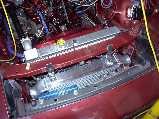
Here's the top view of the intercooler showing the mounting brackets, ignition box and wiring, relays, etc. The hood latch still fits but at some point I will need to make a new center bracket.
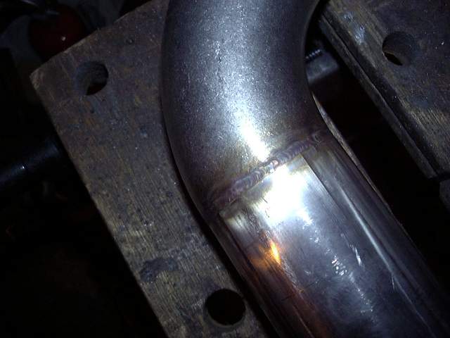
The drivers side intercooler pipe was finish welded at the same time I TIG'ed up the intercooler. I decided to TIG it since it meant that there would be no excess penetration and very little prep before it gets painted.
TIG is such a nice process with no splatter, very little smoke and often no need for filler. Because I had been very careful with my cuts on the pipe (knowing that I would be TIG welding it) I could just make a series of fusion welds. Shown below is what's typical of a TIG weld. Notice the tiny bead, absence of splatter and minimal heating to the surrounding area. I've got to get me one of those...
Three holes were then drilled in the thick 2.5" to 3" transition and then tapped for 1/8" NPT to provide air nipples for the three circuits mentioned previously. I then sanded the entire pipe down with an 80 grit flap wheel and painted with silver/aluminum paint. Once the paint was cured, the BOV and nipples were installed. Plenty of copper gasket goo was used on the BOV and Teflon sealing compound keeps the nipple's threads from leaking.
Here's the top view of the intercooler showing the mounting brackets, ignition box and wiring, relays, etc. The hood latch still fits but at some point I will need to make a new center bracket.
The drivers side intercooler pipe was finish welded at the same time I TIG'ed up the intercooler. I decided to TIG it since it meant that there would be no excess penetration and very little prep before it gets painted.
TIG is such a nice process with no splatter, very little smoke and often no need for filler. Because I had been very careful with my cuts on the pipe (knowing that I would be TIG welding it) I could just make a series of fusion welds. Shown below is what's typical of a TIG weld. Notice the tiny bead, absence of splatter and minimal heating to the surrounding area. I've got to get me one of those...
Three holes were then drilled in the thick 2.5" to 3" transition and then tapped for 1/8" NPT to provide air nipples for the three circuits mentioned previously. I then sanded the entire pipe down with an 80 grit flap wheel and painted with silver/aluminum paint. Once the paint was cured, the BOV and nipples were installed. Plenty of copper gasket goo was used on the BOV and Teflon sealing compound keeps the nipple's threads from leaking.
Thread Starter
Joined: Feb 2001
Posts: 29,798
Likes: 128
From: London, Ontario, Canada
Before the intercooler piping was installed I made a small bracket to keep the TID from wiggling around, heat wrapped the turbo and manifold, then heat wrapped the downpipe. The heat wrap makes a HUGE difference in keeping heat out of the engine bay. With the engine running, you can actually lay your hand on top of the turbine housing for just under 5 seconds before it becomes uncomfortable. The heat wrapping job is far worse then the picture makes it appear since the irregular shape of the turbo and manifold make it difficult. When I upgrade the turbo I will ceramic coat and heat wrap the manifold, but use a blanket on the turbine housing.
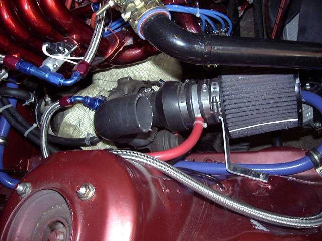
The intercooler pipes were then installed using silicone couplers and T-bolt clamps. Everything went in very easily even though access to some of the clamps is a bit restricted.
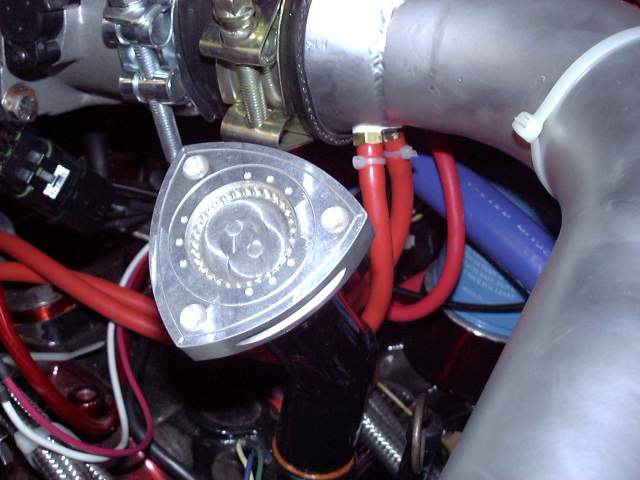
A closeup of the nifty rotor oil cap and air lines to the metering oil nozzles, primary injector air bleeds and purge valve. I zip-tie all my vacuum lines.
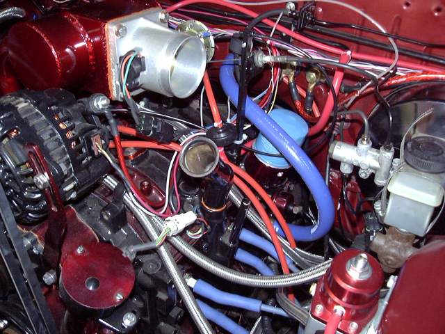
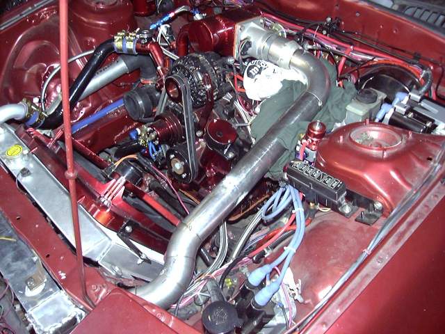
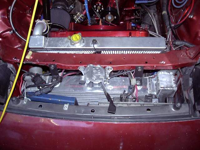
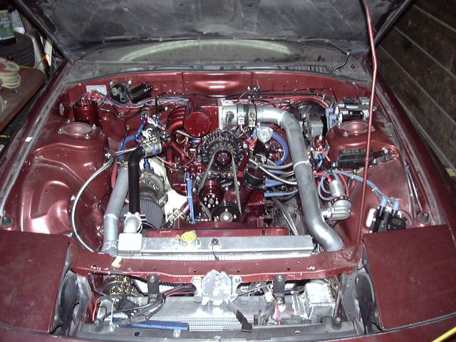
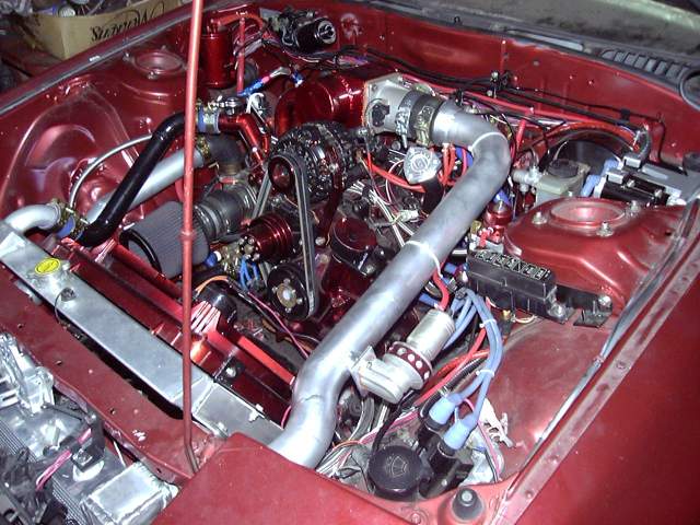
Drivers side view of the completed engine bay.
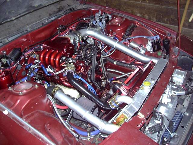
And from the passenger side.
So there you have it. At this point, the car was ready to start. All that remained was to put some gas in the tank, push it out of the garage and turn the key!
This last Saturday was the day when all the little things were looked after. Cables were tied back, hoses clamped down, interior given a quick cleaning, etc. A trip to the gas station on Friday and again on Saturday meant that on Sunday there was 45 liters of fuel in the tank. This is very important on a first start since there is nothing more frustrating then attempting to get a car going only to find out the tank is empty, or to run out halfway through.
Around 1PM on Sunday, Snrub (Jeff) came over as a witness and to provide another set of hands for the last minute tasks. Together we bolted in the seats and seatbelts and did a quick walk-around to make sure that everything was ready to go.
I connected the fuel pump and keyed the car to "RUN" to prime the system. As the Aeromotive pump came to life it groaned for a few seconds as it primed itself then settled down to a steady hum as fuel began to circulate through the system. After a few seconds, the Microtech shut off the pump prime and I got out of the car to check for leaks. None were apparent so it was now time to set the static fuel pressure. I panicked slightly for a moment since it did not seem that I had the appropriately sized Allen key to adjust the Aeromotive fuel pressure regulator but the needle nosed pliers did the job. Fuel pressure was set to 40 PSI, which incidentally is the minimum fuel pressure for the regulator.
Now it was show time so I started the camera, made my introductions and stepped into the car. Once again I primed the fuel system, then turned the key to "START". The engine began to rotate and did one revolution, then another, then another at which point the Microtech synced up to the CAS and started firing ignition and fuel. Another revolution and the engine sprang to life with a roar and cloud of smoke. First try, baby! The silence of the afternoon was cut by the "brap brap brap" as the engine cleared it's throat of assembly lube, vascelene, oil and metal shavings. A large cloud of smoke emanated from the exhaust and fogged the driveway.
I let the engine run a few seconds then gradually let off the throttle as though I somehow expected it to idle. It did not, and simply stalled. An attempt to restart it was rewarded with just a lot of cranking so after a minute or so I gave up, pulled a bunch of fuel out of the cranking map, then tried again. The engine started almost immediately and I held the throttle at 2000 RPM until it had warmed up to operating temperature. Once the engine was warmed, the heater was cranked up to fill the core and circulate coolant to bleed out any air bubbles. After a few minutes the engine was turned off and once again checked for leaks.
None were found so I set the idle speed to about 1500RPM, restarted the engine and pulled fuel from the idle map until it idled by itself.
I couldn't resist so after popping the champagne and sharing a toast with those around I fired up the car and we went for a drive. Since there were no plates nor insurance the drive basically amounted to a trip around the block but it did give me time to check that the transmission and drivetrain is sound. I must say that I am very impressed with how well the car drove, even untuned and with an engine having run a total of about 20 minutes. It took throttle easily, and the large throttle body was not as hard to control as I thought it would be. Compared to a stock RX-7 (and even those with a lightened flywheel) it revs quickly and freely. A little bit more throttle and the turbo wanted to spool up even as low as 2000 RPM. I'm very excited to see how the car responds under boost after it is broken in even with the stock turbo. It currently pulls about 14" of vacuum while idling and about 10" under light load so it should be easy to tune.
There are three minor problems though. There seems to be a slight oil leak from the oil cooler line at the rear iron which is probably just a loose fitting. One of the metering oil lines is also leaking, which is again just likely a loose crimp fitting. And finally there is a fuel leak at the filter input which I suspect is caused by a NPT fitting that was machined a little strange and thus would only go in a few threads. A new fitting is on the way and while I have the car in the air to replace it I'll also take care of the other leaks.
Of course, the whole process was captured on video as I promised last time. That video can be found below. It is about 35 MB and in Windows Media Format. I got lazy and just used Windows Movie Maker since at this point I assume that it's become close enough to a standard at this point. I'm also using the Coral Content Distribution Network to keep some of the load of my servers. The link below should work for almost everyone but if it doesn't, then PM me and I will send you a direct link to the file on my website. You're going to want to right click and "Save As" as there is not enough bandwidth to support streaming.
Project Tina Startup Video
Keep in mind that these videos show an engine that doesn't even have an hour of runtime on it. The fuel maps are all still untuned and the timing isn't even set yet past what is required to start the car.
The intercooler pipes were then installed using silicone couplers and T-bolt clamps. Everything went in very easily even though access to some of the clamps is a bit restricted.
A closeup of the nifty rotor oil cap and air lines to the metering oil nozzles, primary injector air bleeds and purge valve. I zip-tie all my vacuum lines.
Drivers side view of the completed engine bay.
And from the passenger side.
So there you have it. At this point, the car was ready to start. All that remained was to put some gas in the tank, push it out of the garage and turn the key!
This last Saturday was the day when all the little things were looked after. Cables were tied back, hoses clamped down, interior given a quick cleaning, etc. A trip to the gas station on Friday and again on Saturday meant that on Sunday there was 45 liters of fuel in the tank. This is very important on a first start since there is nothing more frustrating then attempting to get a car going only to find out the tank is empty, or to run out halfway through.
Around 1PM on Sunday, Snrub (Jeff) came over as a witness and to provide another set of hands for the last minute tasks. Together we bolted in the seats and seatbelts and did a quick walk-around to make sure that everything was ready to go.
I connected the fuel pump and keyed the car to "RUN" to prime the system. As the Aeromotive pump came to life it groaned for a few seconds as it primed itself then settled down to a steady hum as fuel began to circulate through the system. After a few seconds, the Microtech shut off the pump prime and I got out of the car to check for leaks. None were apparent so it was now time to set the static fuel pressure. I panicked slightly for a moment since it did not seem that I had the appropriately sized Allen key to adjust the Aeromotive fuel pressure regulator but the needle nosed pliers did the job. Fuel pressure was set to 40 PSI, which incidentally is the minimum fuel pressure for the regulator.
Now it was show time so I started the camera, made my introductions and stepped into the car. Once again I primed the fuel system, then turned the key to "START". The engine began to rotate and did one revolution, then another, then another at which point the Microtech synced up to the CAS and started firing ignition and fuel. Another revolution and the engine sprang to life with a roar and cloud of smoke. First try, baby! The silence of the afternoon was cut by the "brap brap brap" as the engine cleared it's throat of assembly lube, vascelene, oil and metal shavings. A large cloud of smoke emanated from the exhaust and fogged the driveway.
I let the engine run a few seconds then gradually let off the throttle as though I somehow expected it to idle. It did not, and simply stalled. An attempt to restart it was rewarded with just a lot of cranking so after a minute or so I gave up, pulled a bunch of fuel out of the cranking map, then tried again. The engine started almost immediately and I held the throttle at 2000 RPM until it had warmed up to operating temperature. Once the engine was warmed, the heater was cranked up to fill the core and circulate coolant to bleed out any air bubbles. After a few minutes the engine was turned off and once again checked for leaks.
None were found so I set the idle speed to about 1500RPM, restarted the engine and pulled fuel from the idle map until it idled by itself.
I couldn't resist so after popping the champagne and sharing a toast with those around I fired up the car and we went for a drive. Since there were no plates nor insurance the drive basically amounted to a trip around the block but it did give me time to check that the transmission and drivetrain is sound. I must say that I am very impressed with how well the car drove, even untuned and with an engine having run a total of about 20 minutes. It took throttle easily, and the large throttle body was not as hard to control as I thought it would be. Compared to a stock RX-7 (and even those with a lightened flywheel) it revs quickly and freely. A little bit more throttle and the turbo wanted to spool up even as low as 2000 RPM. I'm very excited to see how the car responds under boost after it is broken in even with the stock turbo. It currently pulls about 14" of vacuum while idling and about 10" under light load so it should be easy to tune.
There are three minor problems though. There seems to be a slight oil leak from the oil cooler line at the rear iron which is probably just a loose fitting. One of the metering oil lines is also leaking, which is again just likely a loose crimp fitting. And finally there is a fuel leak at the filter input which I suspect is caused by a NPT fitting that was machined a little strange and thus would only go in a few threads. A new fitting is on the way and while I have the car in the air to replace it I'll also take care of the other leaks.
Of course, the whole process was captured on video as I promised last time. That video can be found below. It is about 35 MB and in Windows Media Format. I got lazy and just used Windows Movie Maker since at this point I assume that it's become close enough to a standard at this point. I'm also using the Coral Content Distribution Network to keep some of the load of my servers. The link below should work for almost everyone but if it doesn't, then PM me and I will send you a direct link to the file on my website. You're going to want to right click and "Save As" as there is not enough bandwidth to support streaming.
Project Tina Startup Video
Keep in mind that these videos show an engine that doesn't even have an hour of runtime on it. The fuel maps are all still untuned and the timing isn't even set yet past what is required to start the car.

Rotary Enthusiast

Joined: Jan 2002
Posts: 845
Likes: 38
From: Oscoda, MI
Congratulations!
I should add that I enjoyed the video, and with the intercooler piping, the engine bay just looks so much more "the business" than without.
You know, in regard to the gauge pod, instead of felt, maybe you should fabricate some kind of trim panel, black or red in color, that would extend from the bottom of the pod to the top of the center stereo a/c trim panel. Sort of like an extension to the center stereo and shifter trim pieces, making it appear to be one continuous panel, and divide the dashboard in two (red with a clean gloss or satin black center).
Last edited by cluosborne; Sep 20, 2006 at 08:15 PM. Reason: More comments


Aaron,
I'm curious as to why you are running a stock turbo with a bp engine? Is there future plans for a larger frame turbo? Car looks better and better everytime you post...
I'm curious as to why you are running a stock turbo with a bp engine? Is there future plans for a larger frame turbo? Car looks better and better everytime you post...

I love your steering wheel man, hopefully this weekend I will have my car up and ready.
I think that this project has been one of the coolest ones that I have seen on this forum. Goodluck with the break in and don't let them catch you ridin dirtay
ahah jk man
goodluck though
I think that this project has been one of the coolest ones that I have seen on this forum. Goodluck with the break in and don't let them catch you ridin dirtay
ahah jk man
goodluck though

Joined: Dec 2003
Posts: 6,598
Likes: 10
From: Temple, Texas (Central)
Awesome build and writeups. I always enjoy reading your installments. Its great to finally see the car running. I am so glad I don't have a garage that size. I have a large two car garage and barely have enough room. The exhaust sounds great, btw.
Also, about the gauge pod locations, there are a few other options I have discovered. First, 5one5 makes a gauge pod that goes where the drivers door vent is. I personally don't like that because I like having that vent working. They are in the process of making a dual gauge pod that goes where the demister vent is, but it isn't ready. If you use the 3-gauge pod you can re-locate the idiot light cluster to below the radio. Also, autometer makes a DIN insert for 3 gauges. I think someone on the forums was selling something like that as well.
Edit: its not autometer that makes them. Here's the link: http://egauges.com/vdo_acce.asp?Subgroup=Generic_DIN
Last edited by Sideways7; Sep 20, 2006 at 10:49 PM.

dAracIngPhaRmaCist
Joined: Mar 2004
Posts: 877
Likes: 0
From: Fort Lauderdale
Damn, that is some good work... I love the setup. Wonder how it feels. What are you gonna do exterior wise? Are you gonna put a kit on it or just leave it stock? Cause it looks pretty sexy stock (dirty and all.)