
was this part of the smog system?


Thread Starter
Full Member
Joined: Mar 2010
Posts: 51
Likes: 0
From: bell. washington
was this part of the smog system?
88 turbo II project, and found a spark plug plugging this line up? go to stock air box?
also the line the is capped off with the silver looking one way valve? where does that go?
and there is a black valve looking thing near the frame...emisions?
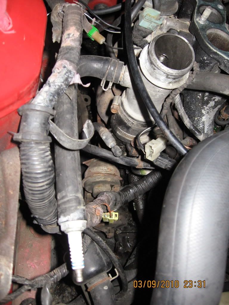
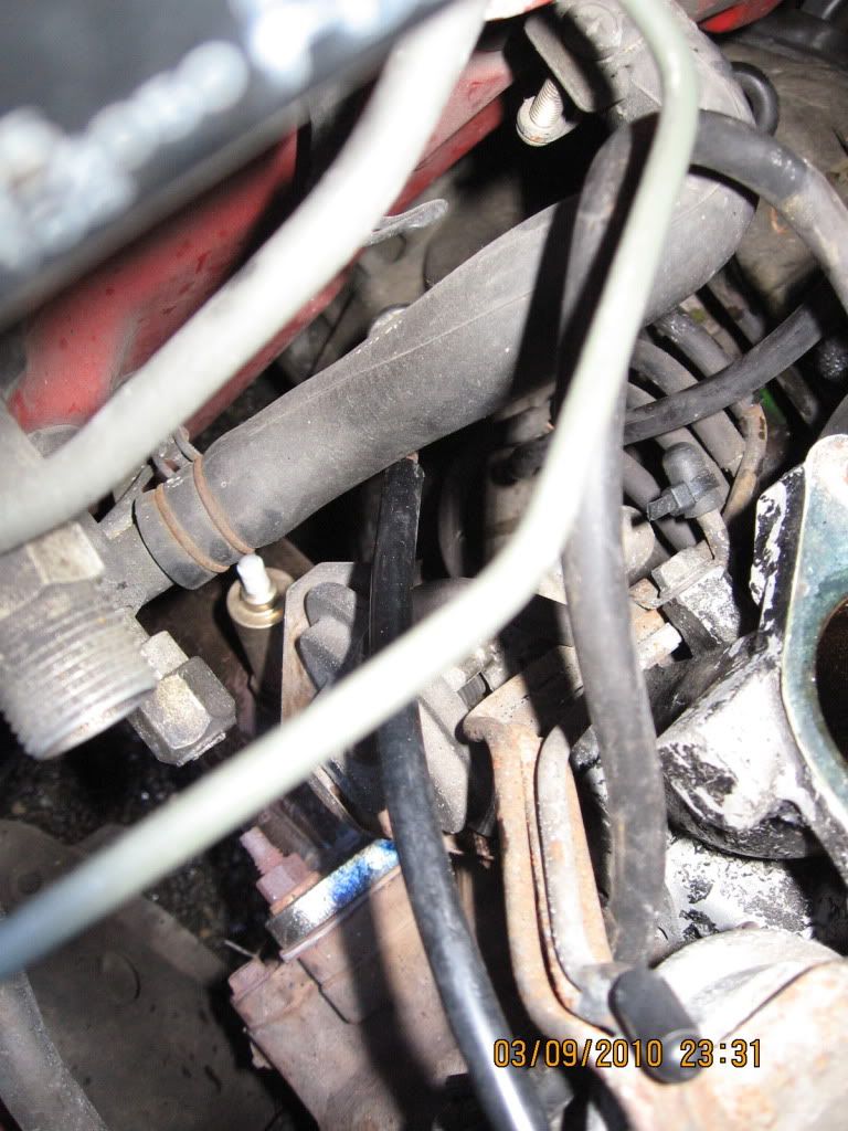
also found 2 ends of a hardline capped off? does this go that zero temp assist?
also the line the is capped off with the silver looking one way valve? where does that go?
and there is a black valve looking thing near the frame...emisions?
also found 2 ends of a hardline capped off? does this go that zero temp assist?
Wow, who the **** owned this car before you? Call them and tell them they are a ******* dumbass.
The line with the spark plug goes to the stock Blow off valve, the line with the silver one way valve needs to hook up the the intake before the turbocharger. It provides vaccum for the evap system.
It looks like your entire emissions system has been hacked up quite a bit. I would reccomend to fully remove everything except for the thermowax pellet in the Throttle body and the BAC valve.
go here for a guide: www.rotaryresurrection.com
Banzai Racing makes a great set of block off plates for this purpose.
Also, keep the air pump, the ACV valve, and the catalytic converter if you need to pass emissions. (doesnt look like you have the airpump anyway.)
Is this a long term project car? Can you spend a decent amount of money on it? How mechanically inclined are you?
If you can afford it, aftermarket engine management does wonders for rotaries. With a system like Haltech, you can completely remove all emissions components except the cat, and tune the fuel maps well enough to pass smog in almost any area.
lol that was one of the parts the prev owner of the car didnt have when he got this engine. so that hose was pplaced on there with a spark plug just so it will run and be able to be moved... tho he never got around to fixing anything i can see. and he must of sold it to you...
Thread Starter
Full Member
Joined: Mar 2010
Posts: 51
Likes: 0
From: bell. washington
Wow, who the **** owned this car before you? Call them and tell them they are a ******* dumbass.
The line with the spark plug goes to the stock Blow off valve, the line with the silver one way valve needs to hook up the the intake before the turbocharger. It provides vaccum for the evap system.
It looks like your entire emissions system has been hacked up quite a bit. I would reccomend to fully remove everything except for the thermowax pellet in the Throttle body and the BAC valve.
go here for a guide: www.rotaryresurrection.com
Banzai Racing makes a great set of block off plates for this purpose.
Also, keep the air pump, the ACV valve, and the catalytic converter if you need to pass emissions. (doesnt look like you have the airpump anyway.)
Is this a long term project car? Can you spend a decent amount of money on it? How mechanically inclined are you?
If you can afford it, aftermarket engine management does wonders for rotaries. With a system like Haltech, you can completely remove all emissions components except the cat, and tune the fuel maps well enough to pass smog in almost any area.
The line with the spark plug goes to the stock Blow off valve, the line with the silver one way valve needs to hook up the the intake before the turbocharger. It provides vaccum for the evap system.
It looks like your entire emissions system has been hacked up quite a bit. I would reccomend to fully remove everything except for the thermowax pellet in the Throttle body and the BAC valve.
go here for a guide: www.rotaryresurrection.com
Banzai Racing makes a great set of block off plates for this purpose.
Also, keep the air pump, the ACV valve, and the catalytic converter if you need to pass emissions. (doesnt look like you have the airpump anyway.)
Is this a long term project car? Can you spend a decent amount of money on it? How mechanically inclined are you?
If you can afford it, aftermarket engine management does wonders for rotaries. With a system like Haltech, you can completely remove all emissions components except the cat, and tune the fuel maps well enough to pass smog in almost any area.
With a standalone, you rip out the stock ecu, harness, and all/most sensors. Then you install the new ECU and build a new harness with much fewer sensors.
Unlike a stock car, with a standalone you only need the following to run your engine:
Intake temp
coolant temp
Manifold Air pressure
Wideband oxygen sensor
Which means you can vastly simplify your engine bay, removing the MAF, resistor pack, idle fuel mixture screw, rats nest, ACV, EGR valve, simplify the evap system, and just generally clean up your engine bay.
Also, a lot of the higher end systems come with a base map that will make your car run as soon as you wire it up, making it possible to drive to your tuner to do further adjustment/dyno runs.

HAILERS
Joined: May 2001
Posts: 20,563
Likes: 27
From: FORT WORTH, TEXAS,USA
Air bypass valve and the check valve for the pruge system both plug into the aft side of the turbo inlet duct (missing?). So your going to buy a Haltech etc for just the lack of a air bypass valve??? Gee. Life's sure is complicated.
Valve is shown in the second jpg. Ignore the red lines, they were meant for another post. The red lines point to where the fuel pump check connector is located.
The two pin, white in color electrical connector in Your picture, is probably from the Port air solenoid or Split Air solenoid on the ACV.....one or the other. There should be a mating connector on the EM harness for it. Not really required for operation of the engine or passing emissions.
Use PAINT to point to items you describe in your jpgs and life will be easier for some of us. The HARD LINES appear to the part of the three vacuum/air lines that go to and from the ACV. Two lines route air and one of the lines routes vacuum to and from the ACV. See attached routing diagram.
The lines are routed like the last two jpgs attached of someones engine I copied off this forum a yr ago or so.
No, what I meant is: if you can afford it, why waste time trying to fix the broken, obsolete, and complicated stock emissions components?
The only reason I still run an RTEK ECU is because i cant afford standalone yet.
The only reason I still run an RTEK ECU is because i cant afford standalone yet.
Trending Topics
Thread Starter
Full Member
Joined: Mar 2010
Posts: 51
Likes: 0
From: bell. washington
Air bypass valve and the check valve for the pruge system both plug into the aft side of the turbo inlet duct (missing?). So your going to buy a Haltech etc for just the lack of a air bypass valve??? Gee. Life's sure is complicated.
Valve is shown in the second jpg. Ignore the red lines, they were meant for another post. The red lines point to where the fuel pump check connector is located.
The two pin, white in color electrical connector in Your picture, is probably from the Port air solenoid or Split Air solenoid on the ACV.....one or the other. There should be a mating connector on the EM harness for it. Not really required for operation of the engine or passing emissions.
Use PAINT to point to items you describe in your jpgs and life will be easier for some of us. The HARD LINES appear to the part of the three vacuum/air lines that go to and from the ACV. Two lines route air and one of the lines routes vacuum to and from the ACV. See attached routing diagram.
The lines are routed like the last two jpgs attached of someones engine I copied off this forum a yr ago or so.
Valve is shown in the second jpg. Ignore the red lines, they were meant for another post. The red lines point to where the fuel pump check connector is located.
The two pin, white in color electrical connector in Your picture, is probably from the Port air solenoid or Split Air solenoid on the ACV.....one or the other. There should be a mating connector on the EM harness for it. Not really required for operation of the engine or passing emissions.
Use PAINT to point to items you describe in your jpgs and life will be easier for some of us. The HARD LINES appear to the part of the three vacuum/air lines that go to and from the ACV. Two lines route air and one of the lines routes vacuum to and from the ACV. See attached routing diagram.
The lines are routed like the last two jpgs attached of someones engine I copied off this forum a yr ago or so.
i have the air inlet tube, not planing on buying a standalone just yet, i figured out the wires that go the the white connnector, at work right now so i will make some detailed pics when i get home but i was just talking about the hardline that has a cap on each end of it, thanks
HAILERS
Joined: May 2001
Posts: 20,563
Likes: 27
From: FORT WORTH, TEXAS,USA
See jpg. It's one of three hardlines that go to the ACV. There should be three of those running together and ending just to the rear of where the ACV goes.Then three rubber vacuum lines attach to those three and the other end of the three new rubber lines go to the ACV.
The aft end of those three hard lines also get three rubber hose attached to them. Those three go a short distance to other hard lines just inbd and aft of them. The OTHER hard lines run to the left side of the engine and attach to the Switching solenoid for one of them and the other two both go to the Relief solenoid.
It's really not as difficult as it may seems. It's just there are no closeup jpgs available. I just happened to have saved the attached jpg from a year or two ago from this forum. Most all the routing can be figured out by looking at the schematic I attached on my first post above. That is a jpg of a decal that came on every turboII car sold in the USA.
It helps to learn what a ACV is and what the name of each solenoid is on the left of the engine. Once you know that, then one can just blow into each hard line and find out where the other end is on the rack and attach that end to the proper solenoid.
The Relief solenoid gets two of the hardlines going to the ACV and it MATTERS which line goes to which nipple on the Relief solenoid. The relief solenoids purpose is to route airpump air from the middle nipple of the ACV to the Relief solenoid.....thru the solenoid and back to the bottom nipple on the ACV....to activate the diaphram on the bottom of the ACV at given times.
