How To: Install a fuel pump kill switch
 10-27-11, 09:13 PM
#1
How To: Install a fuel pump kill switch
How to install a kill switch on an S4 RX7.
Although this may be easy for people to do a guideline is always appreciated. This how-to write up will act as a guide for someone who wishes to install a kill switch in his or her second generation RX7 using the fuel pump relay method. RX7s, especially second generation RX7s, are known for flooding which makes starting the car difficult. This will quickly foul your plugs and your engine oil. Whether you have a freshly built rotary motor, leaky injectors, low compression, or any other starting issues related to fuel flooding a kill switch is the perfect band-aid.
Required items:
16g wire
Wire Stripper
Soldering Iron
Solder
Soldering Flux
Heat Shrink
14-16 Dorman Female Quick Disconnects Part # 85446
Drill with drill bits
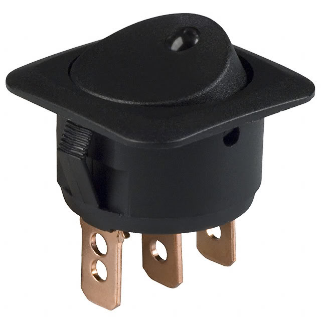
Rocker Switch
Time Required:
1-4 hours depending on skill level and how technical you get
It is always a good idea to disconnect the battery when working on anything electronic. Please remove the (+) cable if not done already.
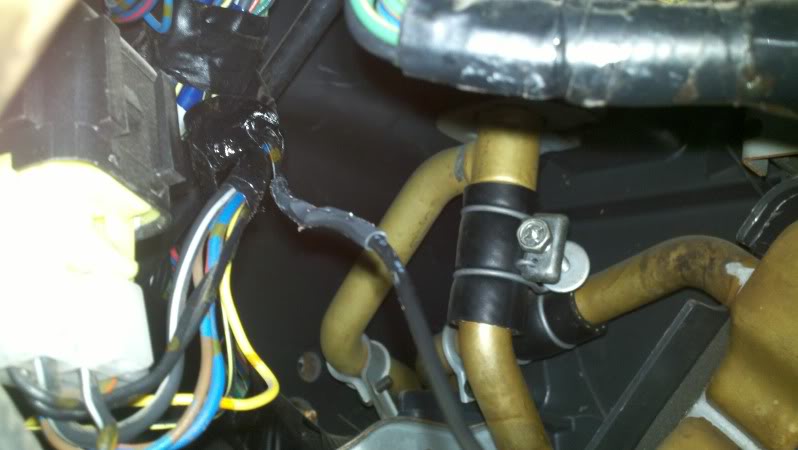
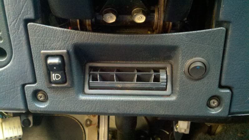
Remove the lower vent under the steering column. It is held together by (2) screws. After removing the screws pull the vent off and note that it is snapped in place. Remove the HVAC hose and squared pipe that is connected to the side of the center console. It is held by (1) screw on the steering column. Locate the Fuel Pump Relay. It is a black/yellow relay with a white connector. The connector is designed for 6 wires but only has 5 wires coming out of it. Here is a picture for reference.
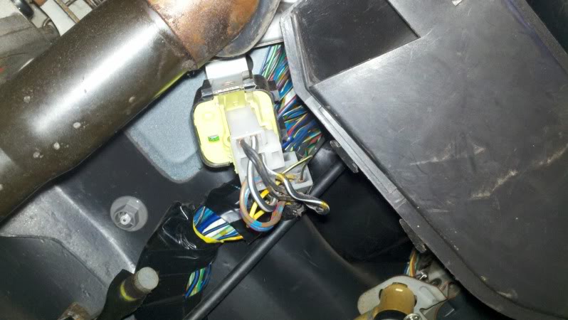
Identify the black/white wire that is coming out the center of the plug. Keep in mind there are (2) black/wires, you want the one coming from the center. (2) wires on one side, (3) wires on the other side. You want the middle wire from the (3) wire side. See the picture for reference.
Disconnect the plug from the relay. Remove about an one inch or more of the electrical tape holding the wires together so you have more wire to work with. Cut the wire at least two inches away from the plug so you will have room for mistakes. Strip the ends of the wire.
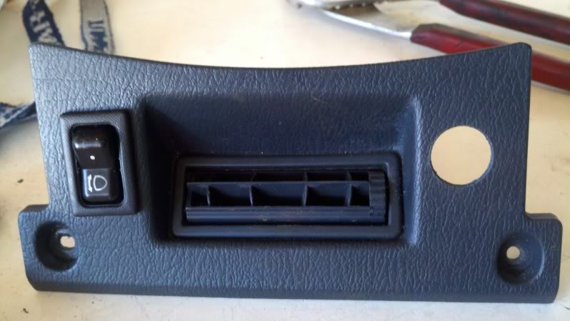
Locate where you want to place the rocker switch. Using the drill and appropriate bit, drill a hole large enough to accommodate the rocker switch. Make sure the switch is on nice and tight. You can use a rubber o-ring (if your rocker switch is round) to make the fit more snug.
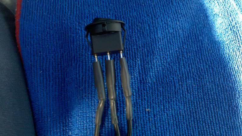
The next step is to prepare the extended wires. It is easier to setup the wires outside where you have more room to work with as the space under the steering column is really tight. Cut the extension wires slightly longer than what is necessary to reach your switch location. I chose the spot just right of the vent because it is convenient for me. You will need (2) extension wires. Strip the ends of both wires. On one end of each extension wire crimp (1) dorman female quick disconnect ensuring they are nice and tight. Use heat shrink to cover the connector crimps and head for insulation and a cleaner look. Use the heat from the soldering iron or a heat gun to shrink the heat shrink around the connector. Cut and add another 1.5 inch of heat shrink and put it on both wires but do not shrink them. These will be use to cover the connection between the extension wire and the relay wire.
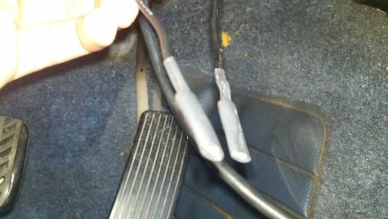
Now you are ready to solder the extension wires to the relay wires. Put soldering flux on both wires and solder the wires together. Refer elsewhere for soldering techniques if you require assistance with soldering. After ensuring the wires are soldered together appropriately pull the extra heat shrink on the wires up and cover the soldered connection. Again, use the heat from the soldering iron or a heat gun to shrink the connection.
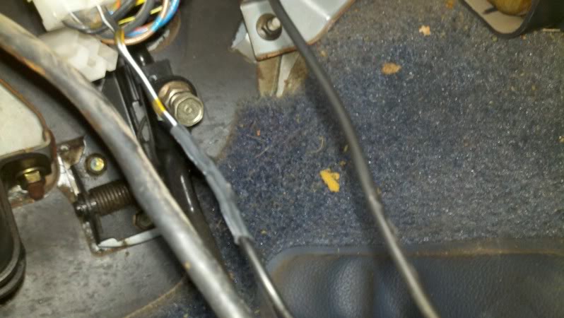
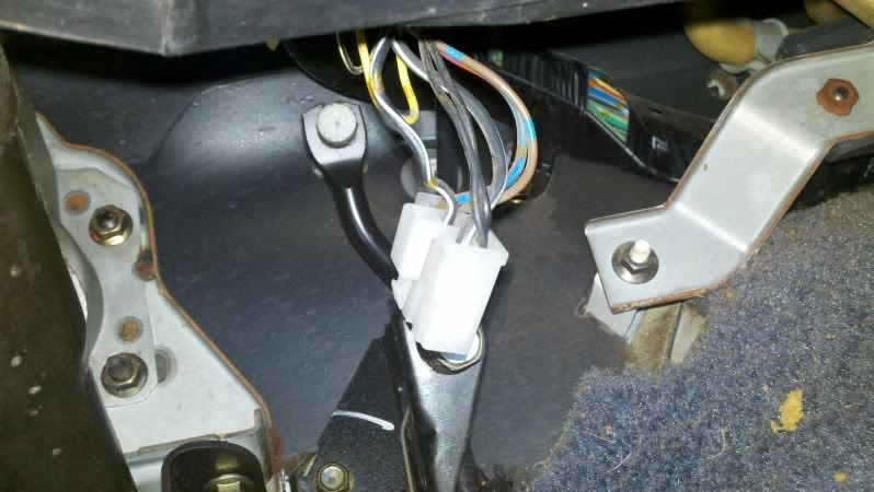
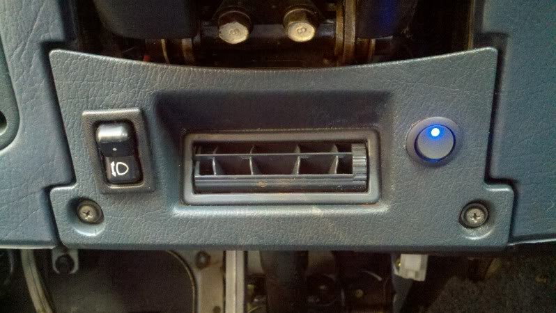
Plug the connector back on the relay. Plug the extended wires onto the rocker switch. Reconnect the HVAC pipes and the vent that was previously removed. If your switch has a built in light, tap into the 12v lighter wire or any other 12v source. When all connectors are attached it should look like this.
Test the switch by starting the car. If the car does not start flip the switch. Try again, the car should start. If the car still does not start check your connections. If it does start, while the car is running, flip the switch off. The car will run for 1-2 seconds then slowly die. You now have a working kill switch. Remove the quick disconnects from the rocker switch keeping note of the on and off position. Put the switch in the desired location. Reconnect the plugs and retest the switch. If all is well you are finished.
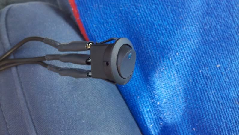
Here it is in the off position.
Here is a picture of the switch in the on position.
-Shaun
Although this may be easy for people to do a guideline is always appreciated. This how-to write up will act as a guide for someone who wishes to install a kill switch in his or her second generation RX7 using the fuel pump relay method. RX7s, especially second generation RX7s, are known for flooding which makes starting the car difficult. This will quickly foul your plugs and your engine oil. Whether you have a freshly built rotary motor, leaky injectors, low compression, or any other starting issues related to fuel flooding a kill switch is the perfect band-aid.
Required items:
16g wire
Wire Stripper
Soldering Iron
Solder
Soldering Flux
Heat Shrink
14-16 Dorman Female Quick Disconnects Part # 85446
Drill with drill bits
Rocker Switch
Time Required:
1-4 hours depending on skill level and how technical you get
It is always a good idea to disconnect the battery when working on anything electronic. Please remove the (+) cable if not done already.
Remove the lower vent under the steering column. It is held together by (2) screws. After removing the screws pull the vent off and note that it is snapped in place. Remove the HVAC hose and squared pipe that is connected to the side of the center console. It is held by (1) screw on the steering column. Locate the Fuel Pump Relay. It is a black/yellow relay with a white connector. The connector is designed for 6 wires but only has 5 wires coming out of it. Here is a picture for reference.
Identify the black/white wire that is coming out the center of the plug. Keep in mind there are (2) black/wires, you want the one coming from the center. (2) wires on one side, (3) wires on the other side. You want the middle wire from the (3) wire side. See the picture for reference.
Disconnect the plug from the relay. Remove about an one inch or more of the electrical tape holding the wires together so you have more wire to work with. Cut the wire at least two inches away from the plug so you will have room for mistakes. Strip the ends of the wire.
Locate where you want to place the rocker switch. Using the drill and appropriate bit, drill a hole large enough to accommodate the rocker switch. Make sure the switch is on nice and tight. You can use a rubber o-ring (if your rocker switch is round) to make the fit more snug.
The next step is to prepare the extended wires. It is easier to setup the wires outside where you have more room to work with as the space under the steering column is really tight. Cut the extension wires slightly longer than what is necessary to reach your switch location. I chose the spot just right of the vent because it is convenient for me. You will need (2) extension wires. Strip the ends of both wires. On one end of each extension wire crimp (1) dorman female quick disconnect ensuring they are nice and tight. Use heat shrink to cover the connector crimps and head for insulation and a cleaner look. Use the heat from the soldering iron or a heat gun to shrink the heat shrink around the connector. Cut and add another 1.5 inch of heat shrink and put it on both wires but do not shrink them. These will be use to cover the connection between the extension wire and the relay wire.
Now you are ready to solder the extension wires to the relay wires. Put soldering flux on both wires and solder the wires together. Refer elsewhere for soldering techniques if you require assistance with soldering. After ensuring the wires are soldered together appropriately pull the extra heat shrink on the wires up and cover the soldered connection. Again, use the heat from the soldering iron or a heat gun to shrink the connection.
Plug the connector back on the relay. Plug the extended wires onto the rocker switch. Reconnect the HVAC pipes and the vent that was previously removed. If your switch has a built in light, tap into the 12v lighter wire or any other 12v source. When all connectors are attached it should look like this.
Test the switch by starting the car. If the car does not start flip the switch. Try again, the car should start. If the car still does not start check your connections. If it does start, while the car is running, flip the switch off. The car will run for 1-2 seconds then slowly die. You now have a working kill switch. Remove the quick disconnects from the rocker switch keeping note of the on and off position. Put the switch in the desired location. Reconnect the plugs and retest the switch. If all is well you are finished.
Here it is in the off position.
Here is a picture of the switch in the on position.
-Shaun

 10-28-11, 03:36 AM
#5
This is my social media.
iTrader: (22)
Join Date: Jan 2006
Location: WA
Posts: 2,744
Likes: 0
Received 0 Likes
on
0 Posts
I have a very similar kill switch set-up. It's not a bad idea to install one of these. Perhaps this should be archived. (If a "kill switch" thread isn't already archived.) People ask about this every so often.
Trending Topics
01-24-12, 07:59 PM
#8
Junior Member

Join Date: Jan 2012
Location: sugar creek missouri
Posts: 0
Likes: 0
Received 0 Likes
on
0 Posts
amazing thred, just got mine done and only took me about 30 min, if that, wrote it up great and no more pulling the egi fuses,,,, thank you thank you thank you lol
 02-28-12, 07:30 PM
#12
I followed this mostly to the T. I have to admit it was relatively easy and quick. The only problem I had was with how cramped that space was and trying to get my switch set up like I had wanted it. I am very happy to have this in here as I run rich and have had my RX7 flood on several occasions which makes me worry for my plugs.
02-29-12, 03:35 PM
#15
This is my social media.
iTrader: (22)
Join Date: Jan 2006
Location: WA
Posts: 2,744
Likes: 0
Received 0 Likes
on
0 Posts
There's a little button on the bottom right of your post that says "Edit"... It comes before the "Quote" button that you all are so familiar with. You're allowed 30 minutes to edit your post. After that 30 minutes, the edit button disappears.
These back to back posts are so repetitive.
These back to back posts are so repetitive.
02-29-12, 07:11 PM
#17
I thought I might add that on this if you're doing it to say a 1986 SE N/A that the plug shown in this picture is going to look slightly different as there is only 1 black and white wire. It's located to the right of your accelerator peddle and is a *&@#$ to strip and cap. Especially if you're not lucky enough to be 5'1 while doing this lol.
03-01-12, 02:22 AM
#18
There's a little button on the bottom right of your post that says "Edit"... It comes before the "Quote" button that you all are so familiar with. You're allowed 30 minutes to edit your post. After that 30 minutes, the edit button disappears.
These back to back posts are so repetitive.
These back to back posts are so repetitive.

 03-01-12, 07:20 PM
#20
Banned. I got OWNED!!!
iTrader: (2)

Join Date: Dec 2011
Location: Albuquerque
Posts: 156
Likes: 0
Received 0 Likes
on
0 Posts
I recently got an engine harness that was "wired for a fuel cutoff switch." On one of the connectors, there were two black w/yellow stripe wires cut I'm assuming this was for the switch. Will wiring a switch to this work?
03-03-12, 01:36 AM
#23
depends on where that blk-yellow wire goes to.
As far as I know, the only wire that has that color comes out the main relay and powers the igniter and fuel injector. You dont really want a switch there unless the switch can handle 30 amps or more. or you can install a 40 amp relay connecting the two blk-yellow wires, and a switch to that relay.
You can also install a relay and switch on the Fuse #7 which powers the circuit opening relay and the main relay.